Module 7 - A202
A202: Identifying and Writing User Needs When ITS Standards Do Not Have SEP Content
HTML of the PowerPoint Presentation
(Note: This document has been converted from a PowerPoint presentation to 508-compliant HTML. The formatting has been adjusted for 508 compliance, but all the original text content is included, plus additional text descriptions for the images, photos and/or diagrams have been provided below.)
Slide 1:

(Extended Text Description: Slide 1: Welcome - Graphic image of introductory slide. A large dark blue rectangle with a wide, light grid pattern at the top half and bands of dark and lighter blue bands below. There is a white square ITS logo box with words “Standards ITS Training” in green and blue on the middle left side. The word “Welcome” in white is to the right of the logo. Under the logo box are the words “RITA Intelligent Transportation Systems Joint Program Office.”)
Slide 2:
Welcome

Shelley Row, P.E., PTOE
Director
ITS Joint Program Office
(Extended Text Description: Slide 2: Screen capture snapshot of RITA website - for illustration only. Below this image is a link to the current website: https://www.its.dot.gov/pcb - this screen capture snapshot shows an example from the RITA website from June 3, 2011. At the top of the page it shows the RITA logo with the text Research and Innovative Technology Administration - Intelligent Transportation Systems. Below the main site banner, it shows the main navigation menu with the following items: About RITA, Communities of Interest, Contact Us, Press Room, RITA Offices, Site Map, and a Search button. Below the main navigation menu, it shows a sub-navigation menu with the following items: About Us, T3 Webinars, ITS Peer-to-Peer, Resources, Local ITS PCB and Testimonials. Beneath the sub-navigation menu, the page is sub-titled "ITS Professional Capacity Building Program" and is divided into sub-sections such as "Welcome to ITS Professional Building", "News", "ITS Technical Assistance" and "Scheduled T3 Webinars". Again, this image serves for illustration only. The current website link is: https://www.its.dot.gov/pcb)
(Note: There is additional text attached to this slide that includes the following introductory information from Shelley Row):
"ITS Standards can make your life easier. Your procurements will go more smoothly and you’ll encourage competition, but only if you know how to write them into your specifications and test them. This module is one in a series that covers practical applications for acquiring and testing standards-based ITS systems.
I am Shelley Row the director of the ITS Joint Program Office for USDOT and I want to welcome you to our newly redesigned ITS standards training program of which this module is a part. We are pleased to be working with our partner, the Institute of Transportation Engineers, to deliver this new approach to training that combines web based modules with instructor interaction to bring the latest in ITS learning to busy professionals like you.
This combined approach allows interested professionals to schedule training at your convenience, without the need to travel. After you complete this training, we hope that you will tell colleagues and customers about the latest ITS standards and encourage them to take advantage of the archived version of the webinars.
ITS Standards training is one of the first offerings of our updated Professional Capacity Training Program. Through the PCB program we prepare professionals to adopt proven and emerging ITS technologies that will make surface transportation safer, smarter and greener which improves livability for us all. You can find information on additional modules and training programs on our web site ITS PCB Home.
Please help us make even more improvements to our training modules through the evaluation process. We look forward to hearing your comments. Thank you for participating and we hope you find this module helpful."
Slide 3:
A202
Identifying and Writing User Needs When ITS Standards Do Not Have SEP Content
Slide 4:
Target Audience
- Engineering Staff
- Project Managers
Slide 5:
Instructor

Raman K Patel, Ph.D., P.E.
President
RK Patel Associates, Inc.
New York, NY, USA
Slide 6:
Curriculum Path (SEP)

(Extended Text Description: A graphical illustration indicating the sequence of training modules for the standards that include Systems Engineering Process content. Each module is represented by a box with the name of the module in it and an arrow showing the logical flow of the modules and the current module highlighted. The first box is labeled “I101 Using ITS Standards: An Overview.” An arrow from this box connects it to a highlighted box labeled “A101 Introduction to Acquiring Standards-based ITS Systems,” representing this module. An arrow from this box connects it to a box labeled “A102 Introduction to User Needs Identification.” An arrow from this box connects it to a box located at the start of the next line labeled “A201 Details on Acquiring Standards-based ITS Systems.” An arrow from this box connects it to a box labeled “A3xxa Understanding User Needs for NTCIP 12xx vxx.” Finally, an arrow from this box connects it to a box labeled “A3xxb Specifying Requirements for NTCIP 12xx vxx.” )
Slide 7:
Curriculum Path (Non-SEP)
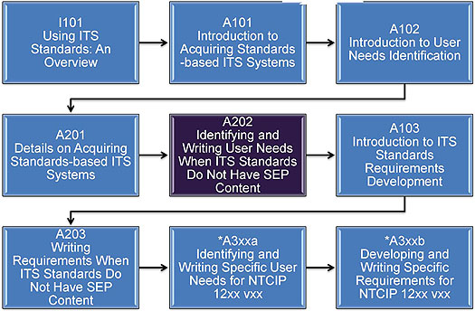
(Extended Text Description: A graphical illustration indicating the sequence of training modules for the standards that do not include Systems Engineering Process content. Each module is represented by a box with the name of the module in it and an arrow showing the logical flow of the modules and the current module highlighted. The first box is labeled “I101 Using ITS Standards: An Overview.” An arrow from this box connects it to a highlighted box labeled “A101 Introduction to Acquiring Standards-based ITS Systems,” representing this module. An arrow from this box connects it to a box labeled “A102 Introduction to User Needs Identification.” An arrow from this box connects it to a box located at the start of the next line labeled “A201 Details on Acquiring Standards-based ITS Systems.” An arrow from this box connects it to a box highlighted and labeled “A202 How to Identify and Write Standards-based ITS User Needs.” An arrow from this box connects it to a box labeled “A103 Introduction to ITS Standards Requirements Development.” An arrow from this box connects it to a box located at the start of the next line labeled “A203 Writing Standards-based ITS System Requirements.” An arrow from this box connects it to a box labeled “A3xxa Identifying and Writing Specific User Needs for NTCIP 12xx vxx.” Finally, an arrow from this box connects it to a box labeled “A3xxb Developing and Writing Specific Requirements for NTCIP 12xx vxx.” The last two boxes contain an asterisk indicating that they are expected to be included in the Year 2 training modules.)
Slide 8:
Recommended Prerequisites
- I101: Using ITS Standards: An Overview
- A101: Introduction to Acquiring Standards-based ITS Systems
- A102: Introduction to User Needs Identification
- A201: Details on Acquiring Standards-based ITS Systems
Slide 9:
Recommended Prerequisites (cont.)
-
Basic knowledge of the following areas is helpful:
- Intelligent Transportation Systems (ITS)
- Managing ITS Deployment Projects
- Government Procurement Processes
- Benefits of Standards
- Systems Engineering Process (SEP)
Slide 10:
Learning Objectives
- Understand Role of User Needs
- Understand Structure of Standards
- Analyze Concept of Operations for User Needs
- Write a User Need
- Extract User Needs from other Relevant Standards
- Validate User Needs
Slide 11:
Learning Objective # 1
Understanding Role of User Needs

(Extended Text Description: A graphic box starts with heading ITS Standards Data-Communications-Equipment. Underneath this box on left there are three rectangular text boxes and there on right side. Both are separated with a line down the middle. Boxes on the left are indicating SEP based standards content. First box states with SEP Content, second box states user needs documented, last or second box states Agencies Select User Needs. On the side of these boxes a vertical text says Modules A102 and A202 addresses these discussion in the boxes. Similarly arranged on the right side, first text box states without SEP Content, second box states User Needs NOT Documented and last /third box states Agencies Infer User Needs. On the right side vertical text A202 is shown.)
Slide 12:
Learning Objective # 1
How do Standards Support Operational Needs?
-
NTCIP device standards provide the interface to facilitate remote access of the field devices to:
- Configure the device
- Monitor the device
- Control the device (functions)
- Retrieve information from the device
- System standards provide the interface to conduct information exchanges among centers
Slide 13:
Learning Objective # 1
NTCIP Device Standards
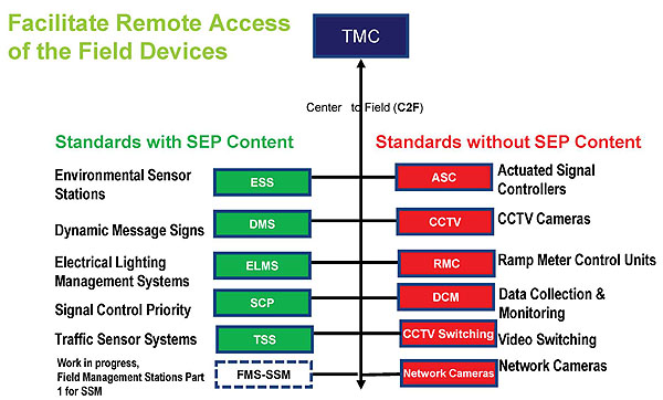
(Extended Text Description: The graphical illustration that depicts two categories of standards under a box at top marked as TMC. A line is shown in the middle that terminates in this box with an arrow. To the left of the line, five green boxes are shown with abbrs inside and spelled out names outside to the left. Above the boxes in the center of the vertical arrow is the word Center-to-Field (C2F). Boxes on the left of the line starts from top with first being ESS for Environmental Sensors, DMS for dynamic message signs, ELMS for Electrical lighting management systems, SCP for signal control priority, TSS for traffic sensor systems, and the last box is dotted marked as EMS-SSM for work in progress on this standard not yet developed. Red Boxes on the right side of the line are indicative of six standards that are without SEP content. They are, from top starting with ASC for actuated signal controllers, CCTV cameras, RMC for ramp meter control units, DCM for Data Collection and Monitoring, CCTV switching for video switching and last one being Network Camera.)
Slide 14:
Learning Objective # 1
Where do Standards Fit?
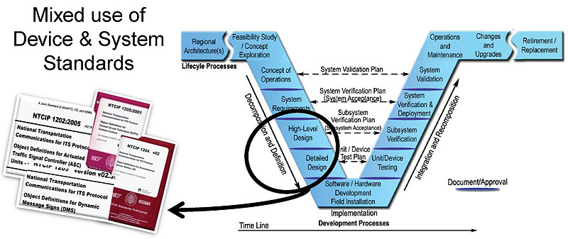
(Extended Text Description: A graphic of the systems engineering process (SEP) is shown. The main graphic of the SEP is a V-shaped diagram with some additional horizontal “wings” on the left and right side of the top of the V. Starting from the left “wing” the steps are regional architecture, needs assessment, concept selection, project planning, and systems engineering management planning. At this point the steps begin to descend the left side of the V with concept of operations, system requirements, high-level design, detailed design, and software hardware and field installation. At this point the steps begin to ascend the right side of the V with unit device testing, subsystem verification, system verification and deployment, system validation, and operations and maintenance. At this point the steps are on the right “wing” of the V with changes and upgrades and retirement/replacement. The following arrows supplement the figure:
- A time line at the bottom of the figure indicating that all steps proceed over time with the steps forming the V overlapping one another.
- A downward arrow on the left side of the V that indicates that these steps deal with decomposition and definition.
- An upward arrow on the right side of the V that indicates that these steps deal with integration and recomposition.
- A horizontal arrow near the bottom of the center of the V that connects the detailed design step to the unit testing step.
- A horizontal arrow a little higher that connects the subsystem requirements step with the subsystem verification step.
- A horizontal arrow a little higher that connects the system requirements step with the system verification step.
- A horizontal arrow near the top of the V that connects the concept of operations step with the system validation step.
Finally, major steps are separated by a barrier that is labeled “document approval.” The slide has a circle drawn over high level design and detailed design and an arrow attached to a circle that is pointing to a side graphic shown with a title page of standards. This illustration shows that standards are located at high level and detailed design level of SEP life cycle. )
Slide 15:
Learning Objective # 1
What Should be in a Specification?
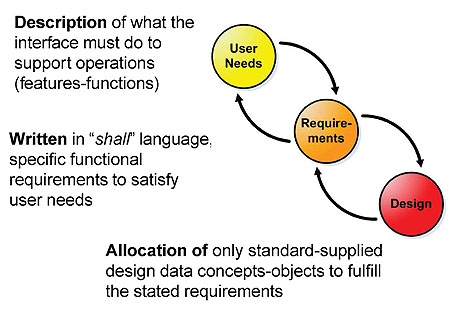
(Extended Text Description: A graphical illustration introduces three circles marked with user needs, requirements and design. The first circle marked as user needs has a curved arrow coming from the second circle marked requirements, and arrow going out to requirements. This depicts that both user needs and requirements are related to each other. Similarly design is connected with requirements with two arrows. Near each circle, text description appears for user needs, requirements and design. Thus, with text and circles we stress that three components make up a specification. Incidentally three Circles have different color shades to show that they are distinct components. To the left of the graphical illustration is the following text, from top to bottom: Description of what the interface must do to support operations (features-functions), Written in "shall" language, specific functional requirements to satisfy user needs, Allocation of only standard-supplied design data concepts-objects to fulfill the stated requirements.)
Slide 16:

Slide 17:
Learning Objective # 1
Problem Definition
What should we do when user needs do not already exist?
Enter your response in the chat pod
Slide 18:
Learning Objective # 1
Develop User Needs When They do not Already Exist
- Module A102 focused on user needs
- Certain standards do not have user needs
- We must first discover them from various sources and standards, and then write them
Slide 19:
Learning Objective # 1
Why do we Have to Write User Needs?
- Allow tracking development at all stages
- They eliminate "guessing or assuming" by developers
- Other reasons....
Slide 20:
Learning Objective # 1
Other Reasons
Consideration for Interoperability
- TMC may need to communicate messages with external centers in the region involving field devices

(Extended Text Description: A small graphic appears below the bullet text to show how two centers exchange information with each other using center to center messages. The graphic has two boxes; first box is labeled as external center or EC in blue and second TMC in yellow. A line is shown between the two with a text next to it that says center to center messages. There is an EC operator symbol of a person connected to each box. This diagram conveys that two operators at different centers need to talk to each other that is exchange information using system interface and for that to materialize we must consider interoperability needs upfront.)
Slide 21:
Learning Objective # 1
Other Reasons
Consideration for Vendor Independence
- Agencies desire multiple (devices/parts) suppliers, interchangeability
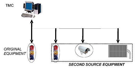
(Extended Text Description: A graphical illustration below text bullet shows a PC located at a TMC and is connected with two headed arrow to a traffic signal shown as original equipment. A set of devices that includes a traffic signal, a CCTV camera and a DMS sign are shown with arrows pointing to them and connected to TMC. This conveys that for devices from multiple vendors can be deployed and added to already that exists. For this to be possible, we must consider user needs upfront.)
Slide 22:
Learning Objective # 1
User Needs Locations on "V" Model
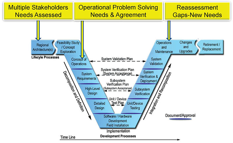
(Extended Text Description: The graphical view of SEP life cycle process used in slide 14 is also used here to show where user needs are located. In this slide, at the top of the Vee, there are three boxes in yellow. The first box is Multiple Stakeholders Needs Assessed and points to Regional Architecture on Vee. Second box marked as Operational Problem Solving and Agreement points to Concept of operations on the Vee, and last one is marked as Reassessment Gaps-New Needs and points to Operations and Maintenance which is on the right top of Vee. From the original presenter's notes: First location: Regional stakeholders identify, discuss, develop consensus, and agree on common user needs for mutual benefits at the regional architecture level. User needs are assessed by the regional architecture process. Second location: Stepping out of the architecture and concept phases, the agency articulates Concept of Operations (ConOps) and scenarios-driven user needs, and defines what a device or system being acquired is to do. All of this is documented in the ConOps. Most of us will agree that both regional architecture and the ConOps plan are a gold mine for user needs. Third location: As shown in the right side of the diagram, at the operations and maintenance stage, user needs are again reassessed. We often find out what works, what doesn’t, and crucial gaps, etc.)
Slide 23:
Learning Objective # 1
Users' Perspective

(Extended Text Description: There are two main bullets with sub-bullets on this slide with the following text:
-
What the system must do to support operational needs:
-
Features/functions
-
Features/functions
-
Support for:
-
Operation Staff-TMC Operators
-
Traffic and System Engineers
- System Maintenance
-
Operation Staff-TMC Operators
Extended Text Description continued: A graphical box is assigned to each on the right side with text. The first box attached to the first bullet meaning is marked as, Basis for development and the second box as Basis for utilization.)
Slide 24:
Learning Objective # 2
Understanding Structure of Standards (1)
- SEP-based Standards provide the following Documented Content:

(Extended Text Description: There are three boxes connected with arrows are shown on slide: The first box is labeled as User Needs, second as Requirements and last is Design Concepts. The slide conveys that SEP based standards provide these three connected content in the document. )
Slide 25:
Learning Objective # 2
Example of SEP-based Content
2.5.2.5 Monitor Water Level
A transportation system operator may need to monitor the depth of water at one or more locations (e.g., over a roadway, in a stream, of a reservoir, etc.).

3.5.2.3.7 Retrieve Water Level
Upon request the ESS shall return the current depth of water at defined locations (e.g., over a roadway, in a stream, of a reservoir etc.).


(Extended Text Description: This slide provides has a sample of user need, requirement and then provides an example of design in a table with three rows and five columns. First column reads Req. ID, second Dialog, third Object ID and last Additional requirements. Under the dialog column, three rows are filled with object ID and last column spells them out as water level sensor tables, index and reading. The content is not important to understand but the organization that indicates that for every selected object, there is a requirement that it supports.)
Source: NTCIP 1207 ESS standard
Slide 26:
Learning Objective # 2
Understanding Structure of Standards (2)
- Non-SEP-based Standards Provide Documentation for:

Some designs such as dialogs may be missing
- We will learn to explore and distinguish user needs from requirements that drive the design
Slide 27:
Learning Objective # 2
Device Standard with SEP Content
Table of Content
Section 1: Concept of Operations/User Needs
Section 2: Functional Requirements
Section 3: Dialogs
Section 4: Management Information Base-MIB
Section 5: Protocol Requirements List-PRL
Slide 28:
Learning Objective # 2
Example of Standard with SEP: NTCIP 1203 v3.03 April 2011
Section 1 GENERAL [Informative] 1
Section 2 CONCEPT OF OPERATIONS [Normative] 19
Section 3 DMS FUNCTIONAL REQUIREMENTS [Normative] 32
Section 4 DIALOGS [Normative] 98
Section 5 MANAGEMENT INFORMATION BASE (MIB) [Normative] 132
Section 6 MARKUP LANGUAGE FOR TRANSPORTATION INFORMATION (MULTI) [Normative] 215
Annexes
Slide 29:
Learning Objective # 2
Device Standard without SEP Content
Table of Contents
Section 1: Overview
Section 2: General
Section 3: Management Information Base-MIB
Section 4: Conformance Groups (CGs)
Slide 30:
Learning Objective # 2
System Standard Without SEP Content
Table of Content
Section 1: Requirements
Section 2: Dialogs
Section 3: Message Sets
Section 4: Data Frames-Data Elements
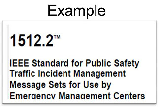
(Extended Text Description: Pullout box example with the text: Example - 1512.2™ - IEEE Standard for Publix Safety Traffic Incident Management Message Sets for Use by Emergency Management Centers.)
Slide 31:
Learning Objective # 2
Recap
-
User Needs:
- Discussed in Module A102
- Form the basis for system development
- Create a path (first step) to interoperability and vendor independence
- We have learned to explore the structure of a standards to prepare specification
Slide 32:

Slide 33:
Learning Objective # 3
Has Your Region Developed a Regional Architecture?
Slide 34:
Learning Objective # 3
Analyzing ConOps for User Needs
-
ConOps Reveals a "Big Picture":
- What is the current situation or problem?
- Who are the users? Who is affected?
- What are the operational scenarios?
- Are there any regional aspects?
Slide 35:
Learning Objective # 3
Where to Find User Needs
- ConOps/Project Concept
- Operational Scenarios
- Regional Architecture
Slide 36:
Learning Objective # 3
Where to Find User Needs (cont.)
- Stakeholders-Interviews
- Assessment Workshops
- Case Studies-Lessons
Slide 37:
Learning Objective # 3
What to Look for in a ConOps?
- What you want to do operationally?
- Specific systems and their intended uses
- What are the expected regional interactions?
Slide 38:
Learning Objective # 3
Operational Scenarios
-
Scenarios are key part of ConOps:
- What is to be done? (Task)
- Who will do what? (Roles)
- What is to be communicated? (Information)
-
Scenarios are managed using Standard Operating Procedures (SOPs)
- Based on lessons learned from the past events
- Carried out by TMC operators
Slide 39:
Learning Objective # 3
Summary
-
We know how to identify user needs from:
- Regional architecture documents and stakeholders
- ConOps and operational scenarios
- Other standards
Slide 40:
Learning Objective # 4
Steps to Writing a User Need
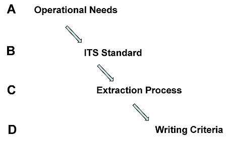
(Extended Text Description: This slide explains four steps, A, B, C and D for writing a user need. Step A Operational Need is followed by a slanted arrow that points to Step B which is ITS Standard. Step B then with a slanted arrow points to Step C which is labeled as Extraction Process. Step C is followed by a slanted arrow to Step D which is labeled as Writing Criteria.)
Slide 41:
Learning Objective # 4
Example: Exploring the Standard
Operational Need

(Extended Text Description: This slide follows up with an example of an operational need to show first steps discussed in previous slide #40. The operation need stated is: Desire to control CCTV cameras from multiple locations during traffic incident management. That is Step A. A slanted arrow then points to Step B which is NTCIP 1205 CCTV standard.)
Slide 42:
Learning Objective # 4
Criteria for Writing a User Need (D)
Step "C" is discussed later
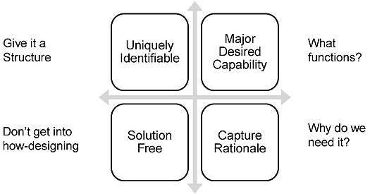
(Extended Text Description: In the center, a graphic is inserted that has four quadrants separated by vertical and horizontal double arrow lines. First top quadrants on the left are labeled Uniquely Identifiable (give it a structure), top right is labeled as Major Desired Capability (What functions?). Bottom left is titled Solution Free (Don’t get into how-designing) and bottom right is titled Capture Rationale (Why do we need it?). )
Slide 43:
Learning Objective # 4
User Need (Structure)
| UN ID # | UN Title |
|---|---|
| UN 1.1 | Control a CCTV camera from more than one location |
Uniquely Identifiable throughout the project development
Reflects the purpose and the context of an operation
Allows tracing of the requirements and helps to validate a "built" system/device
Slide 44:
Learning Objective # 4
User Need (Meaning)
write a major desired capability
"This feature addresses the need for a CCTV camera to be controlled remotely from one or more locations on roadways to manage congestion in the region."
Capture a rationale keep it solution-free
Slide 45:

Slide 46:
Learning Objective # 5
Name a standard without SEP content
Enter your response in the chat pod
Slide 47:
Learning Objective # 5
Extracting User Needs from Relevant Standards
How should we do this?
Slide 48:
Learning Objective # 5
Management Information Base (MIB)
- MIB contains related objects definitions
- Objects represent management information

(Extended Text Description: The slide has a graphic below text with two bullets. The graphic has three ovals on left marked as Object number one, object number two and Object n, all with individual arrow coming out of each and ending in a vertical can-a database symbol-marked in the center as MIB. What this graphic means is that three objects or data elements are part of the database marked as MIB. To the right of the MIB is a text box that gives an example of CCTV with this text: CCTV MIB contains 70 objects in lexicographical order of their object identifiers corresponding to their physical location in the global naming tree, with 12 nodes for CCTV. From the original presenter's notes: MIB is a module, a sort of database that contains objects specific to a field device such as CCTV. Objects definitions are provided for configuring the device, monitoring, and controlling. These functions are carried by implicit actions to a device. (NTCIP does not control a device function, it merely communicates to the device for intended action. This happens by manipulating a value of the control variable).)
e.g. CCTV MIB contains 70 objects in lexicographical order of their OBJECT IDENTIFIERS correspond to their physical location in the global naming tree (12 nodes).
Slide 49:
Learning Objective # 5
Purpose of Objects
- NTCIP Objects are designed to be managed (manipulated) for configuring the device, monitoring the device and controlling the device
Example:
(SET is one of the commands used to "tell" the device what to do)
C Control Objects
P Parameter objects

(Extended Text Description: A graphic illustration below the first bullet is placed on the right side as an example. A line with an arrow is drawn from the management station to a controller unit. This depiction shows how objects are transported from a management station shown on left to a field device such as a traffic controller on the right. On the line a text states SET with objects either C or P and multiple objects may be SET. C stands for control object and P stands for Parameter objects. )
Slide 50:
Learning Objective # 5
Structure of an Object
- Defined by the Abstract Syntax Notation 1 Language (ASN.1)
- Object's name
- Data type value range
- Read-write only
- Conformance requirement
- Human readable description, purpose
- Object Identifier (OID)
(Additional notes for this slide: This slide does not have graphic, but the object structure (below) in six parts, is shaded with light brown color. On the left a list of six parts of the object appears that aligned to the object’s structure.)
3.2.1 maximum number of Presets parameter
rangeMaximumPresets OBJECT-TYPE
SYNTAX INTEGER (0...255)
ACESS read-only
STATUS mandatory
DESCRIPTION "A preset is the pre-specified position where a camera is pointed to a fixed point in space......"
::={cctvRange1}
Slide 51:
Learning Objective # 5
Managed Object
(ASC example)
1. To manage an object the Standard assigns a wide range of values to select from as needed: e.g. 8 phases traffic controller is required
maxPhases OBJECT-TYPE SYNTAX INTEGER (2..255) ACCESS read-only
STATUS optional
DESCRIPTION
"<Definition> The Maximum Number of Phases this Actuated Controller Unit supports. This object indicates the maximum rows which shall appear in the phaseTable object.
<DescriptiveName> NTCIP-1202: :ASC. maxPhases
<DataConceptType> Data Element
<Unit> phase"
::= { phase 1 }
2. To manage this object the Standard has fixed its location on the Internet tree of nodes by providing an unique ID number
Slide 52:
Learning Objective # 5
Summary of what an object does
-
Data content is a Pairing of [OID, Value]
- Fulfills a requirement (design)
- Becomes part of the message sent to the device to perform a desired action
- Future PCB module will cover this topic
Slide 53:
Learning Objective # 5
Conformance Group (CG)
- A CG is a logical grouping of related objects.
- CG helps in determining required objects to support a function.
- One CG for one function
Slide 54:
Learning Objective # 5
Conformance Group (CG)
Example: Motion Control CG
Lists objects necessary to meet user requirement for the remote control of a camera
Objects are gathered from the MIB
They form a logical grouping
- presetGotoPosition
- presetStorePosition
- positionPan
- positionTilt
- positionZoomLens
- positionFocusLens
- positionIrisLens
Slide 55:
Learning Objective # 5
Conformance Group (cont.)
- CGs are used to check the conformance to the standard:
- Mandatory CGs must be selected
Example: CCTV Configuration
- Optional CGs may be selected by user
Example:
- Extended Functions
- Motion Control
- On-Screen Menu Control
Slide 56:
Learning Objective # 5
(Suggested) Extraction Process (C)

(Extended Text Description: The slide has a graphical view of three rectangular boxes: the first one is green and has a text READ with arrow pointing to the next red box marked RECOGNIZE followed by an arrow leading to a blue box titled INFER. Under the boxes there are two text lines. First line begins with CGs below READ box, User need Category below RECOGNIZE box, and Major Desired Capability below INFER box. A second text line begins with MIB (objects), Functions it serves, and required–Design respectively.)
Slide 57:
Learning Objective # 5
READ
Identify Standard: NTCIP 1205

(Extended Text Description: This slide contains a graphic representation of Table 4-2: Conformance Standard Table taken from NCIP 1205 v1 pages 4-5. The full text of the table is included below:
| Conformance Group | Reference | Conformance Requirement |
|---|---|---|
| Configuration | NTCIP 1201:1996 | mandatory |
| Database Management | NTCIP 1201:1996, Amendment 1 | optional |
| Time Management | NTCIP 1201:1996, Amendment 1 | optional |
| CCTV Configuration | NTCIP 1205 | mandatory |
| Extended Functions | NTCIP 1205 | optional |
| Motion Control | NTCIP 1205 | optional |
| On-Screen Menu Control | NTCIP 1205 | optional |
Extended Text Description continued: To the left of thetable is the text "There are 4 CGs" with an arrow pointing to the last four rows of the table.)
Source: NCIP 1205 v1 pages 4-5
Slide 58:
Learning Objective # 5
RECOGNIZE
4.1.1 CCTV Configuration Group page 4-2
4.1.2 Extended Functions Conformance Group page 4-2
4.1.3 Motion Control Conformance Group page 4-3
4.1.4 On-Screen Menu Control Conformance Group page 4-4
We recognize that these four CGs represent four major functionalities.
These four CGs collect 70 objects (design) from 12 listed categories under CCTV MIB.(NTCIP 1205)
Slide 59:
Learning Objective # 5
INFER
Potential User Needs
-
Review Operational Context:
- Provide CCTV functions to support traffic management in the region.
-
Outline Desired Features:
- The features identify and describe the various functions that users may want the device to perform. These features are derived from the high level user needs identified in the problem statement
Slide 60:
Learning Objective # 5
INFER
-
Potential CCTV User Needs (partial list)
- TMC operator may need to configure a CCTV device
- TMC operator may need to control the features within a CCTV
- TMC operator may need to control Pan-Tilt-Zoom features to position the camera
- TMC operator may need to activate the internal camera menu and manipulate control parameters
- User needs can be broken down as sub-needs
Slide 61:
ASC Example
-
Operational context:
-
Remote access from TMC to Configure, Monitor, and Control ASC for:
- Intersection Control
- Overlap
- Coordination (local)
- Coordination (central)
- Priority/Preemption
- Reporting
- Special Functions
- Intra-cabinet Communications
-
Remote access from TMC to Configure, Monitor, and Control ASC for:
Slide 62:
Learning Objective # 5
NTCIP 1202 v02 ASC
- 15 CGs are categorized as per functional areas
- A.3 and A.4 are Mandatory for Conformance
|
Ref |
Areas |
Clause of Profile |
Status |
Support |
|---|---|---|---|---|
|
A.3 A.4 A.5 |
Phase Conformance Group Detector Conformance Group Volume Occupancy Report Conformance Group |
NTCIP 1202-2.2 NTCIP 1202-2.3 NTCIP 1202-2.3 |
M M O |
Yes Yes Yes / No |
|
A.6 A.7 A.8 |
Unit Conformance Group Special Function Conformance Group Coordination Conformance Group |
NTCIP 1202 -2.4 NTCIP 1202- 2.4 NTCIP 1202-2.5 |
O O O |
Yes / No Yes / No Yes / No |
|
A.9 A.10 A.11 |
Time Base Conformance Group Preempt Conformance Group Ring Conformance Group |
NTCIP 1202 -2.6 NTCIP 1202 -2.7 NTCIP 1202 -2.8 |
O O O |
Yes / No Yes / No Yes / No |
|
A.12 A.13 A.14 |
Channel Conformance Group Overlap Conformance Group TS 2 Port 1 Conformance Group |
NTCIP 1202-2.9 NTCIP 1202-2.10 NTCIP 1202-2.11 |
O O O |
Yes / No Yes / No Yes / No |
|
A.15 |
Block Object Conformance Group |
NTCIP 1202-2.12 |
O |
Yes / No |
Additional CGs are also needed from other standards (see NTCIP 1202 v02-2005 standard page 135)
Slide 63:
Learning Objective # 5
List of User Needs for ASC
Source: NTCIP 1202 v02, page 135
| UN | User Need | Mapped to these CG | |
|---|---|---|---|
| 1 | Intersection Control |
|
Mandatory |
| 2 | Overlap |
|
Optional |
| 3 | Coordination (local) |
|
Optional Optional |
| 4 | Coordination (central) |
|
Optional Optional |
| 5 | Priority/Preemption |
|
Optional Optional |
| 6 | Reporting |
|
Optional |
| 7 | Special Functions |
|
Optional |
| 8 | Intra-cabinet Communications |
|
Optional Optional |
Slide 64:
Learning Objective # 5
Writing a User Need for ASC
UN 1.1 Maximum Number of Phase
The system owner needs to be able to manage the operation of the ASC at an intersection that may require support for minimum of eight phases to assign right of way, including pedestrian movements. This includes the ability to program in any combination of 2-8 phases.
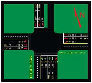
(Extended Text Description: A picture of an intersection is presented at right of the text of UN1.1. The picture shows phasing arrows to indicate turning movements. This illustrates that an intersection with more than two phases. From the original presenter's notes: Based on operational needs listed in the previous slide, in this chart we are providing an example of a user need that deals with number of phases capability desired by the user. The example shows how the criteria to write a user need is used. The photo shows assignment of right of way which determines number of phases needed.)
Note 1: This UN is Mandatory as per CG A.3 of the ASC standard
Note 2: UN is written with ID, title, a major capability, with rationale and it is free of design that is it doesn't say how it is to be met
Slide 65:
Learning Objective # 5
Writing a User Need for CCTV
UN 1.1 Control a Remote CCTV Device
To support an area-wide surveillance of a roadway section a TMC operator may need to remotely access the CCTV device presets and control pan/tilt/zoom (PTZ):
- Zoom and Focus Position Preset
- Tilt angle from = +40 to -90 deg.
Uniquely Identifiable with ID + title
User Need with Major Desired Capability
Rationale
Solution-free
Slide 66:
Learning Objective # 5
Writing User Needs Based on a Scenario
Incident Management
" a TMC operator receives information on a traffic incident and creates an incident report. The operator determines a list of centers who are affected, then begins to inform centers......At some point motorists must be informed.....media informed...
UN # 1 Share incident information with the motorists
UN # 2 Provide warnings to the public
UN # 3 Share information with relevant authorized centers
Slide 67:
Learning Objective # 5
Writing a User Need for Emergency Management
Example of IEEE 1512 Family of Standards
UN 1.1 Share Incident Information with First Responders
An EM center operator may need to know about the roadway incident (in real-time) to be able to make decision and dispatch first responders to the location immediately thereafter, resulting in improved incident response times thus saving lives.
-
This User Need meets the following criteria:
- Uniquely Identifiable with ID + Title
- User Need with Major Desired Capability
- Rationale
- Solution-free
Slide 68:
Learning Objective # 5
Acknowledging Risks
-
Extraction process has some risks:
- Two users may end up with different inferences
- Interoperability may be hurt
- Missing data must be developed
Slide 69:
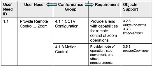
Learning Objective # 5
Traceability with CGs
- Ensures that user needs are met
- Ensures that objects are selected for requirement(s)
(Extended Text Description: This slide contains a graphic representation of a table. The full text of the table is included below:
| Use Need ID | User Need | Conformance Group | Requirement | Object Support |
|---|---|---|---|---|
| 1.1 | Provide Remote Control....Zoom | 4.1.1 CCTV Configuration | Provide a lens with capabilities for remote control of zoom operations |
3.2.8 rangeZoomlimit 3.3.3 timeoutZoom |
| 4.1.3 Motion Control | Provide mode of operation, stop movement and offset measurements | 3.5.3 postionZomelens |
Extended Text Description continued: At the top of the table there are arrows to the left and right of the Conformance Group column header text pointing to adjacent column headers, User Need and Requirement, respectively.)
Slide 70:
Learning Objective # 6
Validating User Needs
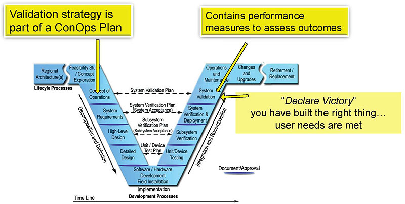
(Extended Text Description: Vee diagram graphic explained in Slide #14 is again presented here to show how it is used for validating user needs. On the left a text shaded in yellow points to Concept of operations on Vee diagram and states Validation strategy is part of the ConOps plan. On the right a text box in yellow points to System validation on the Vee diagram. A statement Declare Victory appears on this portion of the Vee. )
Focus is on User Needs at all stages
Slide 71:
What Have We Learned Today?
1. When user needs don't already exist; we have to develop them
2. User needs are a first step towards achieving interoperability and interchangeability
3. User needs can be found in a ConOps plan
4. User needs can be derived from operational scenarioswhich are part of a ConOps plan
Slide 72:
What Have We Learned Today? (cont.)
5. Non-SEP based standard's structure provide Conformance Groups (CGs) and Management Information Base (MIB)
6. This course taught us a four step extraction process: Read , Recognize , Infer and Write .
Slide 73:
What Have We Learned Today? (cont.)
7. User needs must be written using a prescribed criteria:
Uniquely Identifiable
Major desired Capability
Capture Rationale
Solution-free
8. System is Validated with user needs
Slide 74:
Next Module: A203
Writing Requirements When ITS
Standards Do Not Have SEP Content
-
The participants will learn to:
- Identify different types of requirements.
- Understand that requirements development is a process.
- Avoid pitfalls when writing requirements.
- Write requirements when an ITS communication standard does not have SEP information.
- Use traceability matrices as tools for requirements development.
Slide 75:
Student Supplement
Table of Contents Learning Objectives
- Understand Role of User Needs
- Understand Structure of Standards
- Analyze Concept of Operations for User Needs
- Write a User Need
- Extract User Needs from other Relevant Standards
- Validate User Needs
References
Slide 76:
Additional Information Sources
- Systems Engineering for ITS Handbook, FHWA
- NTCIP Guide
- TMDD Guide
- IEEE 1512 Implementation Guide
Slide 77:

Slide 78:
Here are some questions....
- What is the difference between compliance and conformance?
- What is the difference between validation and verification process?
- Will there be training courses on CCTV or ASC type of devices?