Module 11 - A313a
A313a: Understanding User Needs for ESS Systems Based on NTCIP 1204 v04 Standard
HTML of the PowerPoint Presentation
(Note: This document has been converted from a PowerPoint presentation to 508-compliant HTML. The formatting has been adjusted for 508 compliance, but all the original text content is included, plus additional text descriptions for the images, photos and/or diagrams have been provided below.)
Slide 1:

(Extended Text Description: Welcome - Graphic image of introductory slide. A large dark blue rectangle with a wide, light grid pattern at the top half and bands of dark and lighter blue bands below. There is a white square ITS logo box with words "Standards ITS Training - Transit" in green and blue on the middle left side. The word "Welcome" in white is to the right of the logo. Under the logo box is the logo for the U.S. Department of Transpotation, Office of the Assistant Secretary for Research and Technology.)
Slide 2:

(Extended Text Description: This slide, entitled "Welcome" has a photo of Ken Leonard, Director, ITS Joint Program Office, on the left hand side, with his email address, Ken.Leonard@dot.gov. A screen capture snapshot of the home webpage is found on the right hand side - for illustration only - from August 2014. Below this image is a link to the current website: www.its.dot.gov/pcb - this screen capture snapshot shows an example from the Office of the Assistant Secretary for Research and Development - Intelligent Transportation Systems Joint Program Office - ITS Professional Capacity Building Program/Advanced ITS Education. Below the main site banner, it shows the main navigation menu with the following items: About, ITS Training, Knowledge Exchange, Technology Transfer, ITS in Academics, and Media Library. Below the main navigation menu, the page shows various content of the website, including a graphic image of professionals seated in a room during a training program. A text overlay has the text Welcome to ITS Professional Capacity Building. Additional content on the page includes a box entitled What's New and a section labeled Free Training. Again, this image serves for illustration only. The current website link is: https://www.its.dot.gov/pcb.)
Slide 3:
A313a: Understanding User Needs for ESS Systems based on NTCIP 1204 v04 Standard
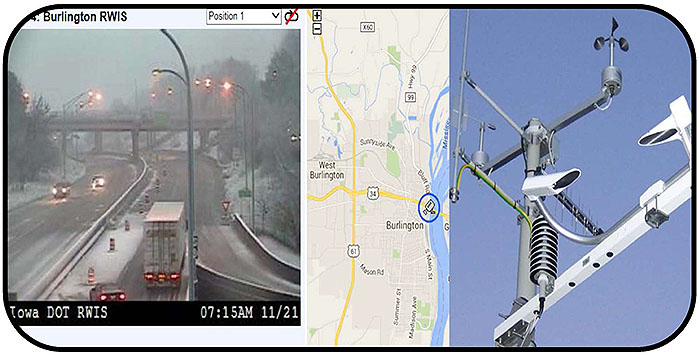
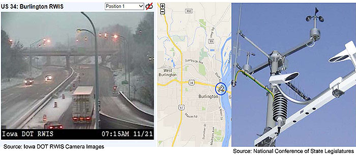
(Extended Text Description: Author's relevant description: Title slide Module A313a: Understanding User Needs for ESS Systems based on NTCIP 1204 v04 Standard - The slide presents a graphic image under the title that shows a CCTV field photo of a roadway condition on left and on the right side a structure with multiple ESS sensors. In the middle a map of an area is shown. The image together conveys that this module is about ESS sensors installed in roadway environment. )
Slide 4:
Instructor

Raman K. Patel, Ph.D.,P.E.
President
RK Patel Associates, Inc.
New York City, NY, USA
Slide 5:
Learning Objectives
- Review the structure of the standard
- Identify specific ESS operational needs
- Use the PRL to select the user needs and traceability to requirements
- Discuss how to prepare a project level PRL for ESS specification
Slide 6:
Learning Objective 1
- Review the structure of the standard
Slide 7:
Terminology
Sensor
Sensor is a device that responds to a physical stimulus and transmits a resulting impulse to a remote processing unit
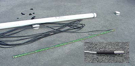
Source: Temperature Probe, FHWA
Slide 8:
Terminology
Environmental Sensor Station (ESS)
Location on the Roadway/Bridge

(Extended Text Description: Author's relevant description: Terminology: ESS Two images are shown to introduce what ESS looks like in the field. This image on left shows a standing structure with multiple sensors installed on it.)
Source: MDOT
ESS collects weather data using range of sensors

(Extended Text Description: Author's relevant description: Terminology: ESS Two images are shown to introduce what ESS looks like in the field. This image on right shows a bridge structure where ESS is installed.)
Source: FDOT Bridge Wind Speed Monitor Installation. FHWA
Slide 9:
Terminology
Remote Processing Unit (RPU) is a Part of a Controller
- As part of a field controller, RPU collects and transmit data to the management station
- RPU is located close to sensors

(Extended Text Description: Author's relevant description: Terminology: RPU photo is shown at left side with an arrow from Management Station pointing to RPU. RPU is a 2070 controller that has RPU fitted inside.)
Source: City of Overland Park, KS
Slide 10:
Terminology
Road Weather Information System (RWIS)
RWIS is a network of ESS that relay road and weather conditions to a computer system
Slide 11:
Terminology

(Extended Text Description: Author's relevant description: Terminology; Types of RWIS - Three types of RWIS are shown on right side: At Top- a permanent fixed location based ESS shown with management station linked to RPU and an air quality sensor. In the middle, a portable mobile station is shown with RPU and ESS. At the bottom, a transportable-vehicle based ESS is shown with a link from the management station. The meaning conveyed states that fixed stations are location based, portable station can be relocated, and transportable stations are vehicle based: all convey weather data management station.)
Slide 12:
Terminology
Flashing Beacons
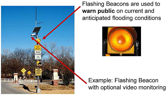
(Extended Text Description: Author's relevant description: Terminology: Flashing Beacons - A photo of a beacon at location is shown with a flasher-a signal head fitted with a bulb. Two fixed Signs below indicate High Water and Road Closure message. A bulb image is shown on right.)
Source: FHWA
Slide 13:
Terminology

(Extended Text Description: Author's relevant description: Terminology: Example IOWA DOT RWIS - A list of seven ESS sensors are presented, each pointing with an arrow to the tower fitted with relevant sensor. This image is on the right side. The list of sensors listed include: 1. Wind speed and direction sensor. 2. Antenna for communications. 3. Traffic speed and traffic count sensor. 4. Pan-tilt-zoom color camera. 5. Precipitation and visibility sensor. 6. Air temperature and Relative Humidity sensor. 7. Road surface temperature sensor and sub surface termperature sensor below pavement. At bottom left corner another image shows IOWA DOT center with a man explaining though Video their RWIS system. The link for this 2 minutes' video clip is shown below: - The video explains each sensor and how overall RWIS helps IOWA DOT.)

Slide 14:
NTCIP Framework

(Extended Text Description: Author's relevant description: NTCIP Framework: A graphic of the communication five levels of the NTCIP standards. On the right-side corner, there is a vertical text box that reads NTCIP 1204/NTCIP 1201 which points to Information Level Data Dictionaries and underneath arrow points to SNMP at Application level. This is shown to empathize where these standards are located. The next level is called the Application Level and includes C2C XML, DATEX, FTP, TFTP, SNMP, and STMP. The next level is called the Information Level and includes C2C Messages, Files, Data Objects, and Dynamic Objects. The next higher level is called the Subnetwork Level and includes PPP, Ethernet, and PMPP. The next level is called the Transport Level and includes TCP/IP, UDP/IP, and T2/NULL. These boxes are connected to an overarching box also in the Information Level labeled Functional Area Data Dictionaries with the left-hand side identifying C2C Data Dictionaries and the right-hand side labeled NTCIP Data Dictionaries. The bottom level, last level, is the Plant Level and includes boxes for Dial-up, Fiber, Coax, Wireless, Twisted Pair, and Leased Line.)
Source: NTCIP Guide

Slide 15:
Reference Architecture for ESS
Major Components of ESS System
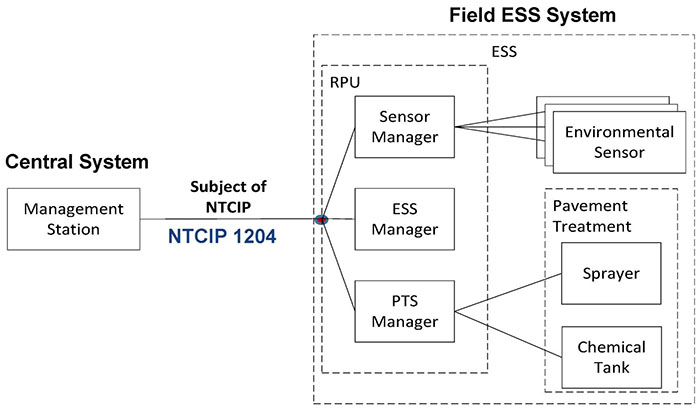
(Extended Text Description: Author's relevant description: Major Components of ESS System - A layout is shown: On the left a management station is connecting to a field ESS system shown on the right side. ESS system has three boxes showing Sensor manager, ESS manager and PTS manager. Several sensors are connected to each manger.)
Slide 16:
History of NTCIP 1204 Standard
ESS Standard has Evolved to v04 in 2016
NTCIP 1204 v01
(1998), Non-SEP
(2001), Amendment-1, Reflected Actual Implementations.
NTCIP 1204 v02
(2007), SEP-based
Added new Features, e.g. de-icing.
NTCIP 1204 v03
(2009), Updated SEP content
Added test procedures, issued Errata for Annex C.
NTCIP 1204 v04
(2015), Supports newly identified user needs, such as Connected Vehicles (CV), reflects lessons learned from deployments.

Slide 17:
Standard Organization
Structure of the Standard (NTCIP 1204 v04)
Section 1 - General
Section 2 - Concept of Operations (Features-User Needs)
Section 3 - Functional Requirements
Section 3.3 - Protocol Requirements List (PRL)
Section 4 - Dialogs
Section 5 - Object Definitions (Management Information Base-MIB)

Slide 18:
Standard Organization
Structure of the Standard (NTCIP 1204 v04)
Annex A - Requirements Traceability Matrix (RTM)
Annex B - Object Tree
Annex C - Test Procedures
Annex D - Documentation of Revisions
Annex E - User Requests
Annex F - Generic Clauses
Annex G - Encoding of Sample Block Objects
Annex H - Controller Configuration Objects
Slide 19:
Standard Organization
How Does the Structure Relate to the Agency ESS/RWIS Specification?
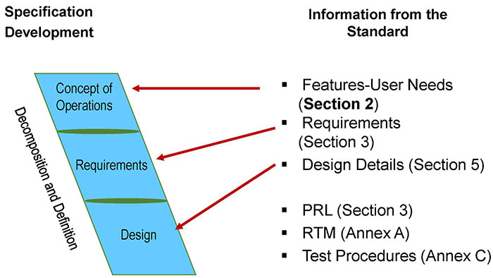
(Extended Text Description: Author's relevant description: The slide has a slanted text box on left with ConOps, Requirements and Design. Text from right is pointing to each of these with an arrow.-
- Features-User Needs (Section 2)
- Requirements (Section 3)
- Design Details (Section 5)
- PRL (Section 3)
- RTM (Annex A)
- Test Procedures (Annex C)
)
Slide 20:
Standard Organization
Standard Structure Supports
Road Weather Data Collection Service Package
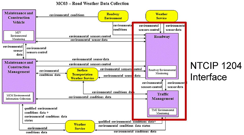
(Extended Text Description: Author's relevant description: ESS relationship to ITS service package MC03 is shown here, with focus on TMC interface. RWIS Service Package: The slide has a layout with boxes and dataflow arrows Each box is marked with text. The layout conveys the RWIS service package. The meaning is that NTCIP 1204 does support RWIS service package. MC03-Road Weather Data Collection (Service Package) Description - This service package collects current road and weather conditions using data collected from environmental sensors deployed on and about the roadway (or guideway in the case of transit related rail systems). In addition to fixed sensor stations at the roadside, sensing of the roadway environment can also occur from sensor systems located on Maintenance and Construction Vehicles. The collected environmental data is used by the Weather Information Processing and Distribution service package to process the information and make decisions on operations. The collected environmental data may be aggregated, combined with data attributes and sent to meteorological systems for data qualification and further data consolidation. The service package may also request and receive qualified data sets from meteorological systems.)
Slide 21:
Standard Organization
User Needs (Features) NOT Covered by v04 Standard
- Configuration details about how a device calculates the current reading sampling periods
- File Transfer Protocol (FTP) to transfer files such as camera snapshots across their agency's network
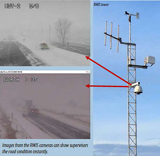
Source: Iowa DOT
Slide 22:

Slide 23:
Question
Which of the following is NOT a Correct Statement Related to the ESS Standard?
Answer Choices
- Standard Supports RWIS
- Standard Supports Communications Interface
- Provides Traceability Tools
- States Sensor Hardware Requirements
Slide 24:
Review of Answers
 a) Standard Supports RWIS
Incorrect. Statement is true, standard does support a range of environmental sensors.
 b) Standard Supports Communications Interface
Incorrect. Statement is true, standard does provide communications capabilities between ESS and a management station.
 c) Provides Traceability Tools
Incorrect. Statement is true, standard provides PRL and RTM tools which a project can tailor for local needs.
 d) States Sensors Hardware Requirements
Correct! Statement is FALSE, ESS standard does not cover physical-hardware requirements for sensors.
Slide 25:
Learning Objectives
- Review the structure of the standard
- Identify specific ESS operational needs
Slide 26:
Learning Objective 2
- Identify Specific ESS Operational Needs
Slide 27:
What are Your Operational Objectives?

(Extended Text Description: Author's relevant description: A roadway image from Caltrans with vehicles moving in both direction is shown with text boxes on right. The slide conveys the Roadway environment. Who is affected is listed as Roadways, Motorists, Vehicles, and Assets.)
Slide 28:
What are Your Operational Objectives?
Roadway Operational Environment Weather Variables
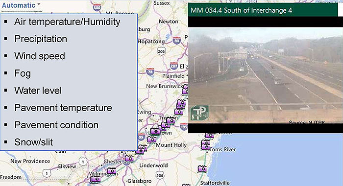
(Extended Text Description: Author's relevant description: A roadway CCTV image is shown on the right side, a regional map is the background. Bulleted items are listed as follows:
- Air temperature/Humidity
- Precipitation
- Wind speed
- Fog
- Water level
- Pavement temperature
- Pavement condition
- Snow/slit
)
Slide 29:
What are Your Operational Objectives?
Weather Events Adversely Impact Roadway Operations
- Rain and Flooding
- Snow and Ice
- Low Visibility
- Hurricanes
- High Winds
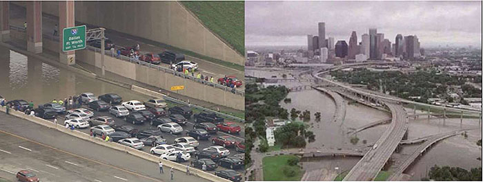
(Extended Text Description: Author's relevant description: Several images of roadways with weather events are shown on this slide: the top two show traffic flow in flooded roadway and Houston highways under water. The meaning of this slide is that weather events adversely impact roadway operations.)
Source: TX DOT
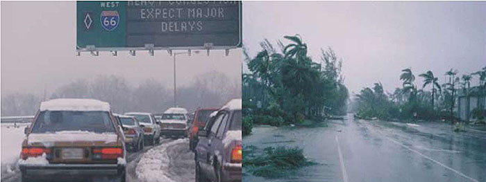
(Extended Text Description: Author's relevant description: Several images of roadways with weather events are shown on this slide: these show a roadway with high wind condition, and a roadway with snow. The meaning of this slide is that weather events adversely impact roadway operations.)
Source: FHWA
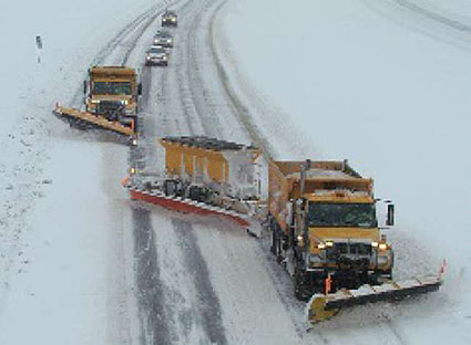
(Extended Text Description: Author's relevant description: Several images of roadways with weather events are shown on this slide: this one shows a roadway with snow and three vehicles removing snow. The meaning of this slide is that weather events adversely impact roadway operations.)
Source: Iowa DOT
Slide 30:
What are Your Operational Objectives?
Slide 31:
What are Your Operational Objectives?
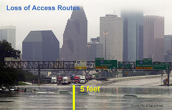
Loss of Access Routes
Courtesy: Michael Martinez and Ben Brumfield, CNN

Slide 32:
What are Your Operational Objectives?
Operational Concerns for Roads-Drivers-Vehicles
| Adverse Impacts | |
| Roadway Conditions | Reduced Capacity/ Access-Throughput-Speed |
| Visibility Impairment | Driver Behavior-Reactions-Safety |
| Traction, Stability Maneuverability | Vehicle Performance, Skidding-Crash Potential |
Slide 33:
What are Your Operational Objectives?
Measuring Adverse Impacts on Safety
- 1.5 million (23%) of annual vehicle crashes in 2015
- Resulting in 800,000 Injuries
- 7,000 fatalities (20% of total 35,092) attributed to weather related vehicle crashes
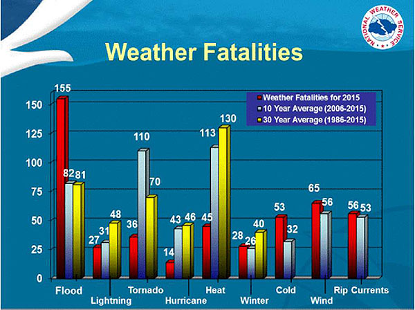
(Extended Text Description: Author's relevant description: A Weather fatalities chart is shown with bars. The chart shows 155 fatalities were attributed to flood in 2015. Other bars shown for heat, tornado etc. The Key Message: Weather impacts on safety are 1.5 million vehicular crashes, resulting in 800,000 injuries and 7,000 fatalities nationally. For example, flood alone stands out in 2015 in terms of fatalities-recent events in 2016 also indicate adverse impacts in cities such as Houston and parts of Midwest region.)
Source: NOAA, National Weather Service
(Based on NHTSA and FHWA 2015 Data)
Slide 34:
What are Your Operational Objectives?
Measuring Adverse Impacts on Mobility
- Road closures reduce Capacity/Speed/ Volume
- Motorists, Traffic Signals, Vehicles-Trucks
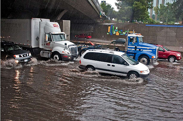
Source : Caltrans
Slide 35:
What are Your Operational Objectives?
Measuring Adverse Impacts on Productivity
- 20% spent on winter maintenance by State DOTs
- Motorists' delays, Maintenance workers safety
- Trucking Loss-$3.5 billion, Roadway damage (potholes, erosions)
"The Pennsylvania Department of Transportation, which had $189.2 million budgeted for the 2013-14 winter, spent $284 million."-PennDOT
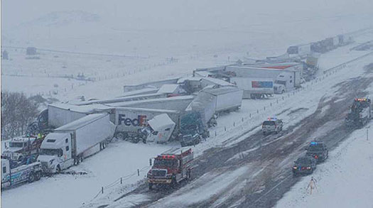
Source: Wyoming DOT
Slide 36:
What are Your Operational Objectives?
Operational Need
Assess Roadway Condition with Sensors-Supplied Data
Central System Management
Station RWIS
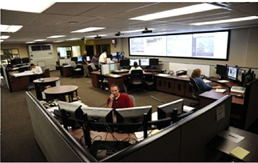
Source: FHWA: WY TMC Note: Wyoming DOT has 62 RWIS Operational

Source: FHWA
Sensors Detect Roadway Conditions
- Visibility impairments
- Precipitation
- High winds
- Temperature extremes
- Pavement friction-condition
- Snow-Ice-Rain....
Slide 37:
What are Your Operational Objectives?
User Needs are Translations of Operational Needs
2.5.2.1 - Monitor Weather Conditions
(affect the transportation system)
2.5.2.1.2 - Monitor Atmospheric Pressure
2.5.2.1.3 - Monitor Winds
2.5.2.1.4 - Monitor Air Temperature

Slide 38:
What are Your Operational Objectives?
Operational Need
Deploy RWIS as a Decision Support System to Take Action
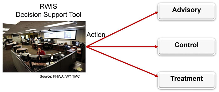
(Extended Text Description: Operational Need - RWIS Decision Support Tool - A TMC is shown taking actions on left side by showing connecting to three text boxes on right side: Advisory, Control and Treatment.)
Slide 39:
What are Your Operational Objectives?
Weather Related Advisory Actions
-
Display Messages on Variable Message Signs
(Covered by NTCIP 1203 Standard) - 511
- Text Message-E Mails
- Web-services
- Media

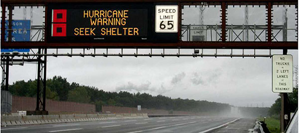
Source: NJTPA-Daktronics
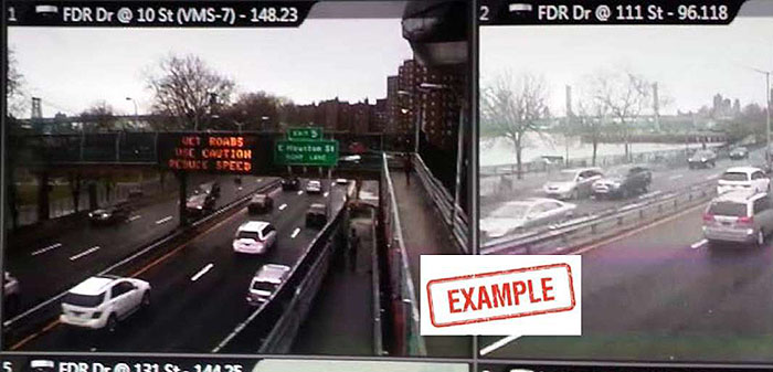
Source: Manual Joshi, NYCDOT TMC

Slide 40:
What are Your Operational Objectives?
Weather Related Control Actions
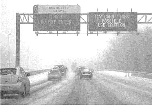
Source: National Conference of State Legislatures

Source: Tennessee Ramp Gate-FHWA

Slide 41:
What are Your Operational Objectives?
Roadway Treatment Actions
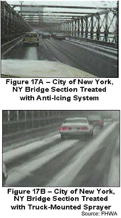
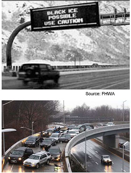

Slide 42:
How Does ESS Standard Support Operational Needs-Features?
Annex F.1.1: Architectural Needs Supports Operational Environment
F.1.1.1. - Provide Live Data: When we always have ON connection
F.1.1.2 - Provide Compressed Data
F.1.1.3 - Provide Off-line Log Data
F.1.2 - Generic Features
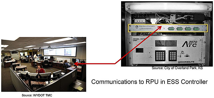
Slide 43:
How Does ESS Standard Support Operational Needs-Features?
Categories of Features Supported

(Extended Text Description: Author's relevant description: Key Message: Operational needs focus on the end use of the ESS device and NTCIP 1204 divides these into 3 major categories:
ESS Manager Features
Section 2.5.1
Sensor Manager Features
Section 2.5.2
PTS Manager Features
Section 2.5.3
PTS-Pavement Treatment System.)

Slide 44:
How Does ESS Standard Support Operational Needs-Features?
ESS Manager Features Supported by Standard
- ESS Manager manages both a Sensor Manager and a PTS Manager
-
ESS Features (2.5.1):
- Generic Features (2.5.1.1)
- Monitor Door Status (2.5.1.2)
- Monitor Power (2.5.1.3)
- Monitor Mobile Station Data (2.5.1.4)
- Determine ESS Type (2.5.1.5)
Slide 45:
How Does ESS Standard Support Operational Needs-Features?
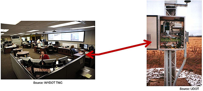
Example: 2.5.1.2 Monitor Door Status
"A transportation system operator may wish to inquire if any doors on the ESS equipment are open..." _

Slide 46:
Deployment Examples
Idaho DOT Statewide Deployments of Weather Stations
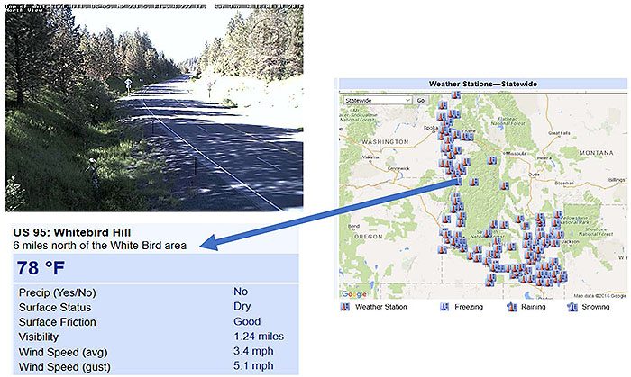
(Extended Text Description: Author's relevant description: Key Message: IDAHO DOT deployments of Weather Stations. Idaho DOT RWIS is shown with field region where ESSs exist, CCTV image and weather data.)
Slide 47:
Deployment Examples
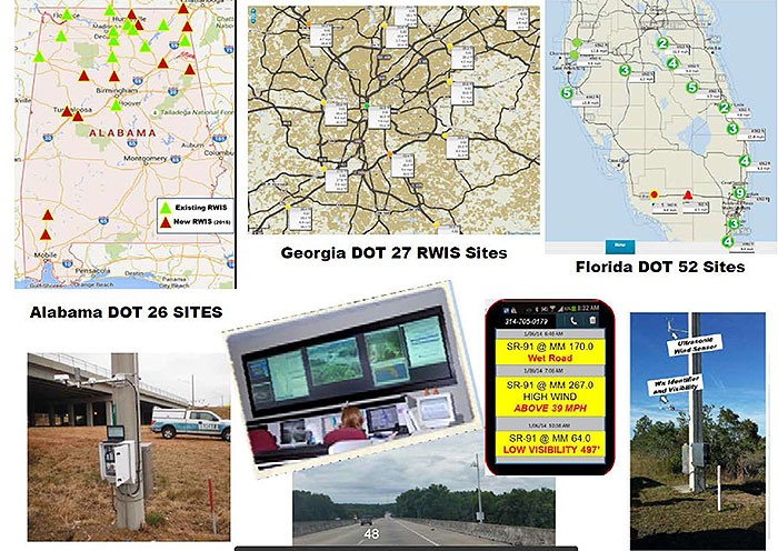
(Extended Text Description: Author's relevant description: A combined deployment example from FHWA source. Top three images show maps where ESSs are located, bottom image on left shows a controller, middle image shows TMC, and right most images shows a pole with ESS mounted on it.)
Source: FHWA
Slide 48:
Deployment Examples

(Extended Text Description: Author's relevant description: FDOT Example with sensors identified such as Ultrasonic Wind Sensor, Road Weather Camera, Precipitation Identifier, etc. Florida I-10 field images are showing ESSs, weather data in text boxes and ESS controller.)
Source: FHWA
Slide 49:
Deployment Examples
Purpose of ESS Deployments by Transportation Agencies
- Collect timely, accurate, and relevant road weather conditions data
- Manage roadways and provide roadway weather information to motorists
- Motorists make travel decisions and adjust to roadway conditions

(Extended Text Description: Author's relevant description: Terminology - A Map of the US is shown with ESS installations in each state. For example, California has 112 and Alaska has 118 ESS in 2008. National Total is 2499, with 2017 ESS in RWIS.)
Source: http://ops.fhwa.dot.gov/weather/mitigating_impacts/essmap.htm: FHWA 2008
Slide 50:
Deployment Examples: ESS Manager
2.5.1.3 Monitor Power
A transportation system operator may wish to monitor the power for the ESS to ensure proper operation.
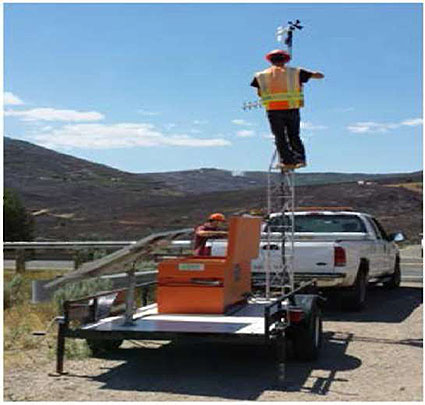
2.5.1.4 Monitor Mobile Station Data
A transportation system operator may wish to monitor the movements of a mobile ESS and, if it is part of a mobile pavement treatment system, monitor the chemicals being dispersed.
2.5.1.1 Generic Features (Device ID...)
Source: UDOT
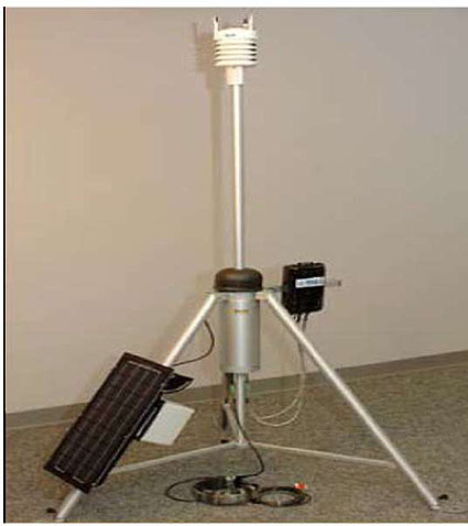
Source: IOWADOT
Slide 51:
Deployment Examples: Sensor Manager

2.5.2 Sensor Manager Features
- Monitor weather conditions
- Monitor pavement
- Monitor subsurface conditions
- Monitor human readings
- Monitor water levels
- Monitor air quality and biohazards
- Monitor mobile weather profile
Slide 52:
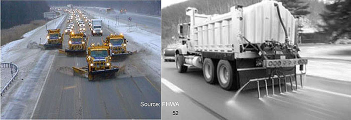
Deployment Examples: PTS Manager
2.5.3.2 Manage Mobile Spray System
A transportation system operator may need to manage the application of anti-icing or de-icing chemicals from a mobile pavement treatment system (e.g., a salt truck).
Slide 53:

Slide 54:
Question
Which of the following is NOT Part of the ESS Standard?
Answer Choices
- Collection of atmospheric and environmental data.
- Monitoring the status of the ESS.
- Assessing if a ESS is a permanent, transportable or mobile.
- Creating a Weather Advisory Message on a Variable Message Sign (VMS).
Slide 55:
Review of Answers
 a) Collection of atmospheric and environmental data.
Incorrect. This feature is supported by the standard.
 b) Monitoring the status of the ESS.
Incorrect. This feature is supported by the standard.
 c) Assessing if a ESS is a permanent, transportable or mobile.
Incorrect. This feature is Mandatory to conform to the ESS standard. All ESS specification must include this user need.
 d) Creating a Weather Advisory Message on a Variable Message Sign (VMS).
Correct! ESS standard does NOT support it, but NTCIP 1203 DMS standard does.
Slide 56:
Learning Objectives
- Review the structure of the standard
- Identify specific ESS operational needs
- Use the PRL to select the user needs and traceability to requirements
Slide 57:
What is a PRL?
Protocol Requirements List (PRL) is a Table, a Matrix
- Provides the standardized relationship between user needs and their requirements
- As a template wth fixed columns and multiple rows it guides users and DMS manufacturers/suppliers
| Protocol Requirements List (PRL) | ||||||
| User Need ID | User Need | FRID | Functional Requirement | Conformance | Support | Additional Specifications |
|---|---|---|---|---|---|---|
| 2.5.2 | Sensor Manager Features | 0.3(1..*) | Yes/No | |||
Slide 58:
What is a PRL?
Standardized Relationship Provided by the Standard
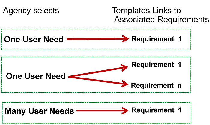
(Extended Text Description: Author's relevant description: Standardized relationship is depicted as: One user need pointing to the right to one requirement with an arrow; one user need pointing to two requirements, and many user needs pointing to one requirement.)
Slide 59:
What is a PRL?
Provides Guidance
(NTCIP 1204 v4, Section 3.3.3, Page 32)
- PRL template guides agency to select project user needs
- PRL then presents associated requirements to fulfill user needs
Table 6 Protocol Requirements List
| Protocol Requirements List (PRL) | ||||||
| User Need ID | User Need | FRID | Functional Requirement | Conformance | Support | Additional Specifications |
|---|---|---|---|---|---|---|
Agency completes the rows with text from the PRL provided by the standard object PRL
Slide 60:
Parts of PRL Provided in the Standard (Section 3.3)
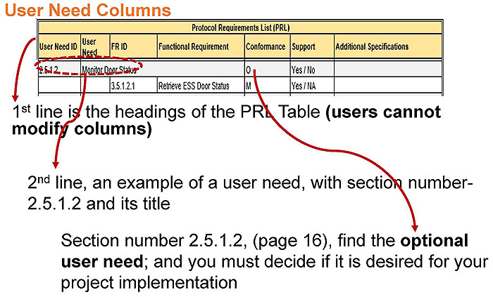
(Extended Text Description: Author's relevant description: PRL table is illustrated with arrows going to sentence below: first line is headings' second line has an example of user need, Section number 2.5.2.2 is shown.
User Need Columns
| Protocol Requirements List (PRL) | ||||||
| User Need ID | User Heed | FR ID | Functional Requirement | Conformance | Support | Additional Specifications |
|---|---|---|---|---|---|---|
| 2.5.1.2 | Monitor Door Status | 0 | Yes/No | |||
| 3.5.1.2.1 | Retrieve ESS DoorSlatus | M | Yes/NA | |||
1st line is the headings of the PRL Table (users cannot modify columns)
2nd line, an example of a user need, with section number-2.5.1.2 and its title
Section number 2.5.1.2, (page 16), find the optional user need; and you must decide if it is desired for your project implementation.)

Slide 61:
Parts of PRL Provided in the Standard (Section 3.3)
Conformance Column

(Extended Text Description: Author's relevant description: PRL table shows fifth column as Conformance. An example of Optional O is shown below PRL with arrow pointing to O, a group of 5 user needs, one must be selected.
| Protocol Requirements List (PRL) | ||||||
| User Need ID | User Heed | FR ID | Functional Requirement | Conformance | Support | Additional Specifications |
|---|---|---|---|---|---|---|
| 2 5.2.1.2 | Monitor Winds | 0.5 in | Yes / No / NA | |||
- Identifies if the user need (or requirement) is Mandatory (M) or Optional (O), plus some from group
- Some basic user needs are considered Mandatory
Example: Determine ESS Type, is it permanent, transportable or mobile?)
Slide 62:
Parts of PRL Provided in the Standard (Section 3.3)
Support/Project Requirement Column
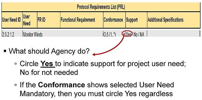
(Extended Text Description: Author's relevant description: PRL table is shown with Sixth column as Support, which is selected Yes or NO. What the agency must do is indicated by selecting YES or NO, is shown with an arrow.
-
What should Agency do?
- Circle Yes to indicate support for project user need; No for not needed
- If the Conformance shows selected User Need Mandatory, then you must circle Yes regardless
)
Slide 63:
Parts of PRL Provided in the Standard (Section 3.3)
Additional Project Requirements-Last Column

(Extended Text Description: Author's relevant description: Last column of PRL is Additional requirements, is available to provide additional details in the table.
| Protocol Requirements List (PRL) | ||||||
| User Need ID | User Heed | FR ID | Functional Requirement | Conformance | Support | Additional Specifications |
|---|---|---|---|---|---|---|
| 2.5.1.4 | Monitor Mobile Station Data | Mobile:M | Yes / NA | |||
| 3.5.1.3.1 | Retrieve Mobile ESS Movement | M | Yes / NA | NTCIP 1204 v04 does not impose any accuracy requirements. Any accuracy requirements should be inserted here. | ||
Provides any additional details about the specific implementation.)
Slide 64:
Parts of PRL Provided in the Standard (Section 3.3)
Agency Determines if an Optional ESS User Need is Required
2.5.2.1.2 Monitor Winds
A transportation system operator may need to monitor the current wind conditions in the vicinity of the ESS and to configure and retrieve the metadata for the wind measurements. This feature allows an operator to determine if vehicle restrictions on a given roadway or bridge span should be issued or to restrict roadway maintenance (e.g., fire alerts).
If the agency selects YES, then certain requirements will be allocated in the project PRL
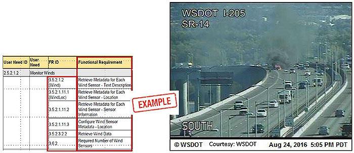
(Extended Text Description: Author's relevant description: A table of PRL is shown with a photo image of a highway section. Key Message: Slide brings up the user need shown in the PRL, and explains, if it is needed or not with rendering or BOS example. First box shows the example user need partial statement; Second box states if it is desired; Third box states, may be not for BOS.)

Slide 65:
Parts of PRL Provided in the Standard
Completing a Project PRL: Functional Requirements

(Extended Text Description: Author's relevant description: Within the PRL this user need – functional requirement relationship is shown via the functional requirements ID and the Functional requirements description column organized right underneath the user needs that these functional requirements address. Figure shows another capture from the PRL table with the focus on the Functional Requirement (FR) identification column and at the Functional Requirement column which contains the description of the requirement. A populated PRL is shown with example requirements, FR ID Functional Requirements, Conformance and Support columns highlighted:.
Section number and the Functional Requirement
| Protocol Requirements List (PRL) | ||||||
| User Need ID | User Need | FR ID | Functional Requirement | Conformance | Support | Additional Specifications |
|---|---|---|---|---|---|---|
| 2.5.2.1.2 | Monitor Winds | 0.5(1..*) | Yes / No / NA | |||
| 3.5.2.1.2 (Wind) | Retrieve Metadata for Each Wind Sensor - Text Description | 0 | Yes / No / NA | |||
| 3.5.2.1.11.1 (WindLoc) | Retrieve Metadata for Each Wind Sensor - Location | 0 | Yes / No / NA | |||
| 3.5.2.1.11.2 | Retrieve Metadata for Each Wind Sensor - Sensor Information | 0 | Yes / No / NA | |||
| 3.5.2.1.11.3 | Configure Wind Sensor Metadata - Location | Wind:0; WindLoc:0 | Yes / No / NA | |||
| 3.5.2.3.2.2 | Retrieve Wind Data | M | Yes / NA | |||
)
Slide 66:
Parts of PRL Provided in the Standard
Partially Filled-in PRL that Provides Standardized Requirement(s) Allocated to Each User Need

(Extended Text Description: Author's relevant description: Key Message: What is a PRL? This slide presents the structure of a PRL, as mapping table and shows rows and columns organization.
| Protocol Requirements List (PRL) | ||||||
| User Need ID | User Need | FR ID | Functional Requirement | Conformance | Support | Additional Specifications |
|---|---|---|---|---|---|---|
| 2.4 | Architectural Needs | M | Yes | |||
| 2.4.1 | Generic Architectural Heeds | M | Yes | |||
| 2.5 | Features | Yes | ||||
| 2.5.1 | ESS Manager Features | M | Yes | |||
| 2.5.1.1 | Generic Features | M | Yes | |||
| 2.5.1.2 | Monitor Door Status | 0 | Yes / No | |||
| 3.5.1 2.1 | Retrieve ESS Door Status | M | Yes / No | |||
| 2.5.1.3 | Monitor Power | 0 | Yes / No | |||
| 3.5.1.2.2 | Retrieve Battery Status | 0.1 (1.*) | Yes / No / NA | |||
| 3.5.1.2.3 | Retrieve Line Volts | 0.1 (1.*) | Yes / No / NA | |||
| 2.5.1.4 | Monitor Mobile Station Data | Mobile:M | Yes / NA | |||
| 3.5.1.3.1 | Retrieve Mobile ESS Movement | M | Yes / NA | NTCIP 1204 vC4 does not impose any accuracy requirements. Any accuracy requirements should be inserted here. | ||
| 2.5.1.5 | Determine ESS Type | M | Yes | |||
| 2.5.1.5.a | Permanent | 0.2 (1) | Yes / No | |||
| 2 5.1.5.b | Transportable | 0.2 (1) | Yes / No | |||
| 2.5.1.5.c (Mobile) | Mobile | 0.2 (1) | Yes / No | |||
| 13.5.1.1.1 | Retrieve ESS Characteristics | M | Yes | |||
| 2.5.1.6 | Monitor the Status of Itie ESS | 0 | Yes / No | |||
| 3.5.1 2.4 | Retrieve ESS Status | M | Yes / NA | |||
| 2.5.2 | Sensor Manager Features | 0.3 (1.*) | Yes / No | |||
The text "Agency prepares a customized project PRL by selecting YES" points to the 7th row of Support.
)
Slide 67:
Benefits of PRL to Stakeholders
Agency Perspective (Project PRL)
- "Communicates" the scope of the desired ESS interface
- Makes it easier to specify what the interface is to do (customize)
- "Spells ouf Conformance requirements; what is needed
- A "Checklist" to validity the built system
- Aid in achieving interoperability
Did they build RIGHT system?

Slide 68:
Benefits of PRL to Stakeholders
Vendors/System Developers Perspective
- Everyone is "connected' on the same page
- Eliminates "guessing" to reduce risks
- Vendors "confirms" ESS functionality + offer optional features

Slide 69:

Slide 70:
Question
Which of the following is NOT a correct approach to preparing the project PRL?
Answer Choices
- Select YES Architectural needs.
- Select Mandatory ESS Manager features ONLY.
- Select YES project-specific features.
- Let the vendor select ESS features.
Slide 71:
Review of Answers
 a) Select YES Architectural needs.
Incorrect. The statement is correct, we must select architectural need to communicate to ESS manager.
 b) Select Mandatory ESS Manager features ONLY.
Incorrect. The statement is correct, we must select Mandatory ESS manager features for conformity to the standard.
 c) Select YES project-specific features.
Incorrect. PRL must select YES optional user need if project requires it to meet operational need. For example, wind speed.
 d) Let the vendor select ESS features.
Correct! The statement is FALSE, the entire purpose of having a PRL in a specification is to "communicate" what an agency desires. A vendor can respond to the PRL.
Slide 72:
Learning Objectives
- Review the structure of the standard
- Identify specific ESS operational needs
- Use the PRL to select the user needs and traceability to requirements
- Discuss how to prepare a project level PRL for ESS specification
Slide 73:
Learning Objective 4
- Discuss How to Prepare a Project Level PRL for ESS Specification
Slide 74:
Steps to Select User Needs and Associated Requirements
Brief Review
- ESS gathers weather data and sends it to the central system management station for further processing
- Central management station "monitors" ESS as part of RWIS
- ESS specification begins with identifying user needs and specifying requirements
Slide 75:
How PRL Fits into the ESS Specification

(Extended Text Description: Author's relevant description: Procurement Contract Specifications - An arrow points to a text box on upper right side. Procurement Contract Specifications text:
1 - Hardware Specifications
Functional Req.
Performance Req.
Structural Req.
Mechanical Req.
Electrical Req.
Environmental Req.
2 - Software Specifications
Functional Req.
Performance Req.
Contractual requirements during:
- System development
- Testing
- Deployment/integration
- Operations/maintenance
- Project management
3 - Communications Interface Specifications
User Needs
Functional Req.
Project PRL, RTM
Testing Documentation
)

Slide 76:
Complete Project PRL with Entries (Populating Table)
Key Points to Remember While Completing a Project PRL
- PRL must be consistent with the hardware specification
- ESS specification should have project level PRL
- PRL must be based on the NTCIP 1204 v04 with SNMP interface
- Include only need-based specific ESS parameters-NOTAII YOU Can GET

Slide 77:
Complete Project PRL with Entries (Populating Table)
Conformance and Compliance Issues
-
Conformance: Meets a specified standard
- To claim "Conformance" to NTCIP 1204 v04, the vendor shall minimally satisfy the mandatory requirements selected (YES)
- Vendors that provide additional features beyond the completed PRL are still conformant as long as they conform with the requirements of NTCIP 1204 v04 and its normative references
- Compliance: Meets a specification
Slide 78:
Complete Project PRL with Entries (Populating Table)
Fill-in PRL with User Needs/Requirements; YES
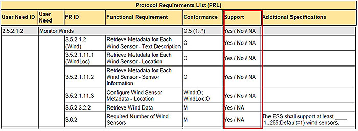
(Extended Text Description: A PRL table with box highlighting Support column is shown:
| Protocol Requirements List (PRL) | ||||||
| User Need ID | User Need | FR ID | Functional Requirement | Conformance | Support | Additional Specifications |
|---|---|---|---|---|---|---|
| 2 5.2.1.2 | Monitor Winds | 0.5(1..*) | Yes / No/NA | |||
| 3.5 2.1.2 (Wind) | Retrieve Metadata for Each Wind Sensor - Text Description | 0 | Yes/No/NA | |||
| 3.5.2.1.11.1 (WindLoc) | Retrieve Metadata for Each Wind Sensor - Location | 0 | Yes / No/NA | |||
| 3.5.2.1.11.2 | Retrieve Metadata for Each Wind Sensor - Sensor Information | 0 | Yes/No/NA | |||
| 3.5.2.1.11.3 | Configure Wind Sensor Metadata - Location | Wind:0; WindLoc:0 | Yes/No/NA | |||
| 3.5.2.3.2.2 | Retrieve Wind Data | M | Yes / NA | |||
| 3.6.2 | Required Number of Wind Sensors | M | Yes / NA | The ESS shall support at least ____ (1..255:Default=1) wind sensors. | ||
)
- Use the Support/Project Requirement column to indicate if the user need is required for the implementation
- If the YES is selected, the PRL identifies the requirements associated with that user need
- Add notes to the last column if required

Slide 79:
Complete Project PRL with Entries (Populating Table)
Addressing Mandatory Needs for Conformity

(Extended Text Description: Author's relevant description: Example PRL table - Conformance column has a box around M in conformance column at top rows and selected YES in Support column. One more user need is shown at end. Selected YES For a project points to Yes in Support column. Additionally, YES for Permanent (NO for Mobile, NO for Transportable) points to Support column 2.5.1.5 section. The table is as follows:
| Protocol Requirements List (PRL) | ||||||
| User Need ID | User Need | FR ID | Functional Requirement | Conformance | Support | Additional Specifications |
|---|---|---|---|---|---|---|
| 2.4 | Architectural Needs | M | Yes | |||
| 2.4.1 | Generic Architectural Needs | M | Yes | |||
| 2.5 | Features | Yes | ||||
| 2.5.1 | ESS Manager Features | M | Yes | |||
| 2.5.1.1 | Generic Features | M | Yes | |||
| 2512 | Monitor Door Status | 0 | Yes /No | |||
| 35.12.1 | Retrieve ESS Door Status | M | Yes / NA | |||
| 2.5.1.3 | Monitor Power | Q | Yes/No | |||
| 3.5 1.2.2 | Retrieve Battery Status | 0.1 (1.*) | Yes/No/NA | |||
| 3.5.1.2.3 | Retrieve Line Volts | 0.1 (1.*) | Yes/No/NA | |||
| 2.5.1.4 | Monitor Mobile Station Data | Mobile:M | Yes / NA | |||
| 3.5.1.3.1 | Retrieve Mobile ESS Movement | M | Yes / NA | NTCIP 1204 v04 does not impose any accuracy requirements. Any accuracy requirements should be inserted here. | ||
| 2.5.1.5 | Determine ESS Type | M | Yes | |||
| 2.5.1.5.a | Permanent | 0.2(1) | Yes / No | |||
| 2.5.1.5.b | Transportable | 0.2(1) | Yes/No | |||
| 2.5.1.5.c (Mobile) | Mobile | 0.2(1) | Yes/No | |||
| 3.5.1.1.1 | Retrieve ESS Characteristics | M | Yes | |||
| 2.5.1.6 | Monitor the Status of the ESS | 0 | Yes/No | |||
| 3.5 1.2.4 | Retrieve ESS Status | M | Yes / NA | |||
| 2.5.2 | Sensor Manager Features | 0.3 (1..*) | Yes / No | |||
)

Slide 80:
Complete Project PRL with Entries (Populating Table)
Addressing Generic Architectural (Communications) Needs

(Extended Text Description: Author's relevant description: Same kind of example as above with items in Conformance and Support highlighted in this table:.
| User Need ID | User Need | FR ID | Functional Requirement | Conformance | Support | Additional Specifications |
|---|---|---|---|---|---|---|
| F.1.1 | Generic Architectural Needs | |||||
| F.1.1.1 | Provide Live Data | M | Yes | |||
| F.2.1.1.1 | Retrieve Data | M | Yes | |||
| F 2.1.1.2 | Deliver Data | M | Yes | |||
| F 2.1.1.3 | Explore Data | M | Yes | |||
| 3.6.21 | Maximum Response Time for Requests | M | Yes | The Response Time for all requests shall be milliseconds (25-500: Defaults 00) | ||
| F.1.1.2 (Compressed) | Provide Compressed Data | Mobile:M; 0 | Yes / No | |||
| 3.6.21 | Maximum Response Time for Requests | M | Yes | The Response Time for all requests shall be milliseconds (25-500: Defaults 00) | ||
| F.1.1.3 | Provide Off-line Log Data | 0 | Yes / No | |||
| F.2.1.2.1 | Retrieve Current Configuration of Logging Service | M | Yes / NA | |||
| F.2.1.2.2 | Configure Logging Service | M | Yes / NA | |||
| F.2 1 2.3 | Retrieve Logged Data | M | Yes / NA | |||
| F.2 1 2.4 | Clear Log | M | Yes / NA | |||
| F.2.1.2.5 | Retrieve Capabilities of Event Logging Service | M | Yes / NA | |||
| F.2.1.2.6 | Retrieve Total Number of Logged Events | M | Yes / NA | |||
)

Slide 81:
Backward Compatibility
NTCIP 1204 v04 Compatibility to Earlier Versions
- v04 is updated for newer user needs and generally backward compatible with v03, v02 and v01
- Previous ESS implementations that used v01 and v02 data objects may not be able to add newer sensor technologies
- v04 PRL and RTM tables headings have been revised

Slide 82:

Slide 83:
Question
Which of the following is a False Statement related to a ESS specification?
Answer Choices
- ESS specification includes a PRL.
- Conformance requires only meeting mandatory user needs.
- Compliance requires only mandatory user needs.
- Vendor must use the project PRL.
Slide 84:
Review of Answers
 a) Agency specification includes a PRL.
Incorrect. The statement is true, PRL must be in every ESS specification.
 b) Conformance requires only mandatory user needs.
Incorrect. Statement is true, only Mandatory user needs must be met to conform to the ESS standard.
 c) Compliance requires only meeting mandatory user needs.
Correct! False statement: Vendor must meet mandatory and selected optional user needs for compliance to specification.
 d) Vendor must use the project PRL.
Incorrect. The statement is true-vendor must use agency PRL.
Slide 85:
Module Summary
- Review the structure of the standard
- Identify specific ESS operational needs
- Use the PRL to select the user needs and traceability to requirements
- Discuss how to prepare a project level PRL for ESS specification
Slide 86:
We Have Now Completed A313a in the ESS Curriculum
 Module A313a: Understanding User Needs for ESS Systems Based on
NTCIP 1204 v04 Standard
 Module A313b: Specifying Requirements for
NTCIP 1204 v04 ESS Standard
 Module T313: Applying Your Test Plan to the Environmental Sensor Stations based on the
NTCIP 1204 ESS Standard v04
Slide 87:
Next Course Module
Module A313b: Specifying Requirements for NTCIP 1204 v04 ESS Standard
Concepts taught in next module (Learning Objectives):
- Review the structure of the standard
- Use the PRL and RTM to specify the standardized structure of requirements
- Use the RTM to specify the standardized design
- How to specify requirements not covered by the standard
- Infer the relationship between selecting requirements and testing
Slide 88:
Thank you for completing this module. Feedback
Please use the Feedback link below to provide us with your thoughts and comments about the value of the training.
Thank you!