Module 12 - A321a
A321a: Understanding User Needs for Traffic Management Systems Based on TMDD v3.0 Standard
HTML of the PowerPoint Presentation
(Note: This document has been converted from a PowerPoint presentation to 508-compliant HTML. The formatting has been adjusted for 508 compliance, but all the original text content is included, plus additional text descriptions for the images, photos and/or diagrams have been provided below.)
Slide 1:
(Extended Text Description: Slide 1: Welcome - Graphic image of introductory slide. A large dark blue rectangle with a wide, light grid pattern at the top half and bands of dark and lighter blue bands below. There is a white square ITS logo box with words “Standards ITS Training” in green and blue on the middle left side. The word “Welcome” in white is to the right of the logo. Under the logo box are the words “RITA Intelligent Transportation Systems Joint Program Office.”)
Slide 2:
Welcome

Shelley Row, P.E., PTOE
Director
ITS Joint Program Office
(Extended Text Description: Slide 2: Screen capture snapshot of RITA website - for illustration only. Below this image is a link to the current website: https://www.its.dot.gov/pcb - this screen capture snapshot shows an example from the RITA website from June 3, 2011. At the top of the page it shows the RITA logo with the text Research and Innovative Technology Administration - Intelligent Transportation Systems. Below the main site banner, it shows the main navigation menu with the following items: About RITA, Communities of Interest, Contact Us, Press Room, RITA Offices, Site Map, and a Search button. Below the main navigation menu, it shows a sub-navigation menu with the following items: About Us, T3 Webinars, ITS Peer-to-Peer, Resources, Local ITS PCB and Testimonials. Beneath the sub-navigation menu, the page is sub-titled "ITS Professional Capacity Building Program" and is divided into sub-sections such as "Welcome to ITS Professional Building", "News", "ITS Technical Assistance" and "Scheduled T3 Webinars". Again, this image serves for illustration only. The current website link is: https://www.its.dot.gov/pcb)
(Note: There is additional text attached to this slide that includes the following introductory information from Shelley Row):
"ITS Standards can make your life easier. Your procurements will go more smoothly and you’ll encourage competition, but only if you know how to write them into your specifications and test them. This module is one in a series that covers practical applications for acquiring and testing standards-based ITS systems.
I am Shelley Row the director of the ITS Joint Program Office for USDOT and I want to welcome you to our newly redesigned ITS standards training program of which this module is a part. We are pleased to be working with our partner, the Institute of Transportation Engineers, to deliver this new approach to training that combines web based modules with instructor interaction to bring the latest in ITS learning to busy professionals like you.
This combined approach allows interested professionals to schedule training at your convenience, without the need to travel. After you complete this training, we hope that you will tell colleagues and customers about the latest ITS standards and encourage them to take advantage of the archived version of the webinars.
ITS Standards training is one of the first offerings of our updated Professional Capacity Training Program. Through the PCB program we prepare professionals to adopt proven and emerging ITS technologies that will make surface transportation safer, smarter and greener which improves livability for us all. You can find information on additional modules and training programs on our web site ITS PCB Home.
Please help us make even more improvements to our training modules through the evaluation process. We look forward to hearing your comments. Thank you for participating and we hope you find this module helpful."
Slide 3:
A321a - Understanding User Needs for Traffic Management Systems Based on TMDD v3.0 Standard
Slide 4:
Target Audience
- Engineering and Planning Staff
- Emergency Management
- Public Safety
- Traffic Management Center (TMC) Operation Staff
- System Developers
- Public and Private Sectors
Slide 5:
Instructor

Raman K Patel, Ph.D., P.E.
PresidentRK Patel Associates, Inc.
New York, NY, USA
Slide 6:
Curriculum Path (SEP)

(Extended Text Description: Curriculum Path (SEP): A graphical illustration indicating the sequence of training modules for the standards that include Systems Engineering Process content. Each module is represented by a box with the name of the module in it and an arrow showing the logical flow of the modules and the current module highlighted.
The first box is labeled “I101 Using ITS Standards: An Overview.” An arrow from this box connects it to a highlighted box labeled “A101 Introduction to Acquiring Standards-based ITS Systems.” An arrow from this box connects it to a box labeled “A102 Introduction to User Needs Identification.” An arrow from this box connects it to a box located at the start of the next line labeled “A201 Details on Acquiring Standards-based ITS Systems.” An arrow from this box connects it to a box labeled “A321a Understanding User Needs for Traffic Management Systems Based on TMDD v3 Standard” (highlighted in purple) Finally, an arrow from this box connects it to a box labeled “Specifying Requirements A311b-A321b.”)
Slide 7:
Curriculum Path (Non-SEP)
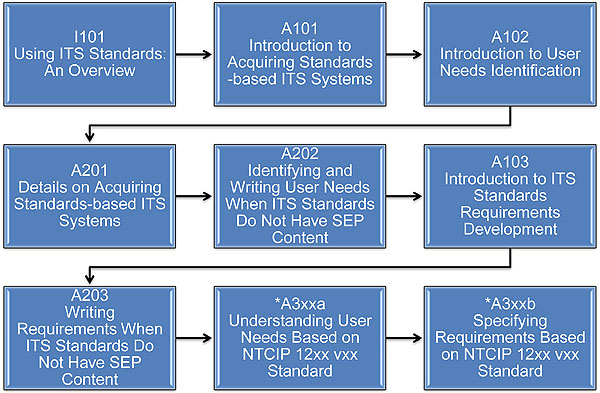
(Extended Text Description: Slide 7: (Curriculum Path (Non-SEP): A graphical illustration indicating the sequence of training modules for the standards that do not include Systems Engineering Process content. Each module is represented by a box with the name of the module in it and an arrow showing the logical flow of the modules and the current module highlighted. The first box is labeled “I101 Using ITS Standards: An Overview.” An arrow from this box connects it to a highlighted box labeled “A101 Introduction to Acquiring Standards-based ITS Systems,” representing this module. An arrow from this box connects it to a box labeled “A102 Introduction to User Needs Identification.” An arrow from this box connects it to a box located at the start of the next line labeled “A201 Details on Acquiring Standards-based ITS Systems.” An arrow from this box connects it to a box highlighted and labeled “A202 How to Identify and Write Standards-based ITS User Needs.” An arrow from this box connects it to a box labeled “A103 Introduction to ITS Standards Requirements Development.” An arrow from this box connects it to a box located at the start of the next line labeled “A203 Writing Standards-based ITS System Requirements.” An arrow from this box connects it to a box labeled “A3xxa Understanding User Needs Based on NTCIP 12xx vxx.” Finally, an arrow from this box connects it to a box labeled “A3xxb Specifying Requirements Based on NTCIP 12xx vxx.” The last two boxes contain an asterisk indicating that they are expected to be included in the Year 2 training modules.)
Slide 8:
Recommended Prerequisites
- I101 Using ITS Standards: An Overview
- A101 Introduction to Acquiring Standards-based ITS Systems
- A102 Introduction to User Needs Identification
- A201 Details on Acquiring Standards-based ITS Systems
Slide 9:
Recommended Prerequisites (cont.)
Basic knowledge of the following areas is helpful:
- Intelligent Transportation Systems (ITS)
- Managing ITS deployment projects
- Government procurement processes
- Benefits of standards
- Systems Engineering Process (SEP)
- Traffic Management Centers (TMCs)
Slide 10:
Learning Objectives
- Describe what problem TMDD is addressing
- Identify regional operational and planning needs (specific to TMDD) for common system interface to support interagency communications
Slide 11:
Learning Objectives (cont.)
- Discuss the TMDD v3.0 standard structure and the content
- Understand the role of NRTM and learn how to use it to select user needs and link them to requirements
- Identify a requirement of institutional arrangement for implementing a system interface
Slide 12:
Learning Objective #1
What is the Traffic Management Data Dictionary (TMDD)?
- Provides high level definitions of user needs, requirements and data concepts
- Used in System Interface specification
- Supports Center-to-Center (C2C) communications needs
Slide 13:
Learning Objective #1
Centers

(Extended Text Description: Relevant descriptive information provided by author for this figure: This graphic shows two buildings and two separate arrows pointing to each other to convey their definitions. The building on the left is called External Center that desires information and the building on the right is called Owner Center that provides information and has direct control of field devices. Over the two arrows in the center appears a text box that says Center-to-Center communications (C2C).)
Slide 14:
Learning Objective #1
Interoperability
" The ability of two or more systems or components to exchange information and to use the information that has been exchanged" -IEEE Std 610
Slide 15:

Slide 16:
Learning Objective #1
Why do centers desire to communicate with each other?
Type your response in the chat pod
Slide 17:
Learning Objective #1
Before Standardization
Each Center Requires Multiple Proprietary Interfaces

(Extended Text Description: Relevant descriptive information provided by author for this figure: This graphic shows five buildings of different shape with four set of colored bidirectional arrows going into a cloud that connects all of them. The set of colored arrows depicts that if any center wants to communicate with others, they all require multiple interfaces-one for each colored arrow - without standardization. The point is that centers will need multiple interfaces that are proprietary if standardization is not used.)
Slide 18:
Learning Objective #1
After Standardization
Each Center Requires One Standard-based Interface
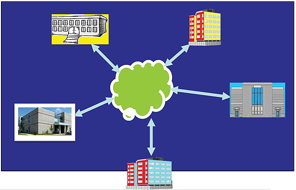
(Extended Text Description: Relevant descriptive information provided by author for this figure: This graphic is the same as in the previous slide, but centers are now only shown with one color arrow pointing to cloud, meaning that with standardization, centers only require one interface that is common to all centers.)
Slide 19:
Learning Objective #1
What is a System Interface?
"a system interface is a shared boundary across which information is passed"
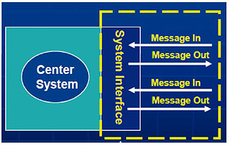
(Extended Text Description: Relevant descriptive information provided by author for this figure: This slide has a large square blue background box. On the left side inside this box a circle with text Center System appears, next to circle which a vertical rectangular box with text system interface appears. This conveys that both share a boundary. Into and out of system interface box, one set of separate arrows that shows message in and message out connects to outside world. Another set appears bellow to show that more than one messages flow in and out of system interface that makes boundary with the center system. Finally, a broken square border appears over system interface and messages in-out to show that together they make a boundary with the center system to provide capability of messaging. The entire graphic conveys system interface definition.)
Slide 20:
Learning Objective #1
System Interface Implementation
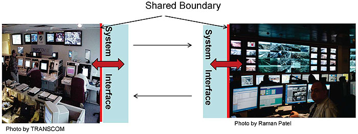
(Extended Text Description: Relevant descriptive information provided by author for this figure: This slide provides real world photos of two TMCs: one on left is a photo of TRASCOM center and one on right is NYC Joint TMC. Both centers are shown with system interface on side of photos and two separate arrows flow between these TMC to show that they have a common system interfaces that communicate information to each other. This information exchange then is used to manage assets and other entities, manage information, monitor status and control devices. The slide graphics have made a point that these real-world center operations use common system interface to carry out operations in real-time and improve their efficiency.)
SI Uses:
- Manage assets and other entities
- Manage information
- Monitor status
- Control devices
Slide 21:
Learning Objective #1
Procuring System Interface
Specification Components Supplied by TMDD v3 standard
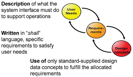
(Extended Text Description: Relevant descriptive information provided by author for this figure: A graphical illustration introduces three circles marked with user needs, requirements and design concepts. The first circle marked as user needs has a curved arrow coming from the second circle marked requirements, and arrow going out to requirements. This depicts that both user needs and requirements are related to each other. Similarly design is connected with requirements with two arrows. Near each circle, text description appears for user needs, requirements and design concepts. Thus, with text and circles we stress that three components make up a specification. Incidentally three circles have different color shades to show that they are distinct components.)
Slide 22:
Summary of Learning Objective 1
What Problem is TMDD Addressing?
- Recognizes a need for a system interface to exchange information among centers
- System Interface design uses ONLY standardized "building materials"
- Same set of user needs, requirements, and data concepts is to be included in specification to achieve interoperability among centers
Slide 23:

Slide 24:
Learning Objective #2
What operational needs will a TMC have for information from another center?
Type your response in the chat pod
Slide 25:
Learning Objective #2
Operational Environment
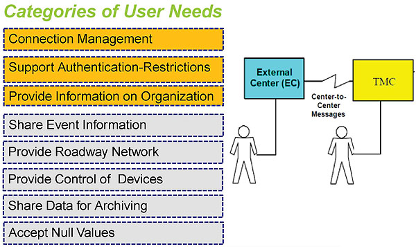
(Extended Text Description: Relevant descriptive information provided by author for this figure: A vertical stack of eight rectangular text boxes lists eight categories of user needs that are present in a typical operational environment. Next to the stack is graphic that shows an External Center (EC) with operator is communicating with a TMC with operator and link in between two canters. The list of Categories of User Needs on the left includes the following, from top to bottom: Connection Management, Support Authentication-Restrictions, Provide Information on Organization (all three highlighted), Share Event Information, Provide Roadway Network, Provide control of Devices, Share Data for Archiving, Accept Null Values.)
Slide 26:
Learning Objective #2
Example
2.3.1 Need for Connection Management
2.3.1.1 Verify Connection Active
Centers need to verify that a connection with another center is alive or active.2.3.1.2 Need to Support Requests

(Extended Text Description: Relevant descriptive information provided by author for this figure: This examples show a graphic in the middle with two centers with separate arrows shown in between. The meaning conveyed is that centers communicate to meet user needs. In this example the user need is to management connection between two systems.)
2.3.1.3 Need to Support Subscriptions
2.3.1.4 Need to Support Error Handling
Slide 27:
Learning Objective #2
Example
2.3.4 Need to Share Event Information
2.3.4.6 Need for Current Event Information
External centers need to obtain current event information from owner centers such as a description, location, severity, and status of the event.

(Extended Text Description: Relevant descriptive information provided by author for this figure: This is the same graphic that is in Slide 26 but the user need is to share event information.)
2.3.4.7 Need for Planned Event Information
.....need to obtain planning information.....
Slide 28:
Learning Objective #2
Example
2.3.5 Need to Provide Roadway Network Data
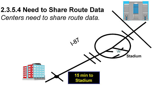
(Extended Text Description: Relevant descriptive information provided by author for this figure: User need is to provide roadway network data. The graphic shows a center at top and one at bottom of the with a road network diagram in between lies the stadium. The roadway has a DMS located near the center at lower end. Motorists are traveling to the stadium, so travel time on a DMS shows 15 minutes from the center at lower end.)
Slide 29:
Learning Objective #2
Example
2.3.6.4 Need to Share DMS Status and Control
2.3.6.4.4 Need to Display a Message on a Remote DMS
Centers need to request that a specific message be displayed on a DMS controlled by another center.

(Extended Text Description: Relevant descriptive information provided by author for this figure: This graphic is the same as Slide 26, with two centers with separate arrows shown in between, except user need is to share DMS status.)
Slide 30:
Learning Objective #2
Example
2.3.7 Need to Share Data for Archiving
2.3.7.1 Need for Traffic Monitoring Data
Centers exchange traffic monitoring data, such as volume, occupancy, and speed for archival purposes.
Data collection for planning and research needs

(Extended Text Description: Relevant descriptive information provided by author for this figure: This graphic is the same as the graphic in Slide 29, except user need is to provide data for archiving. It also includes a map underneath the arrows connecting the two sides of the figure, indicating the monitoring of traffic volumes.)
Monitoring traffic volumes on another agency's roadway
Slide 31:
Learning Objective #2
Illustration
How centers share and use current information
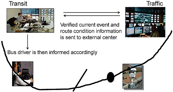
(Extended Text Description: Relevant descriptive information provided by author for this figure: In this graphical layout a transit center is shown on left side of the slide and a TMC is shown on the right side. A bus with the driver is shown below transit center. This layout is designed to show how centers share current information and use it to meet their operational need. A roadway section is passing through both jurisdictions on which an incident occurs near TMC where a CCTV camera is also located to verify conditions.
The point of this illustration is that the transit center request information on current condition of the roadway link so that it may decide to inform its bus drivers and perhaps take alternate route to avoid prolong congestion.
Upon Transit is center’s request, the TMC verifies current conditions on the route with CCTV, and then TMC responds with current information. Transit center then passes that information to the bus drivers, and presumably advises them to avoid congested route. This is done in real-time.)
Slide 32:
Learning Objective #2
Illustration
How centers share field devices?
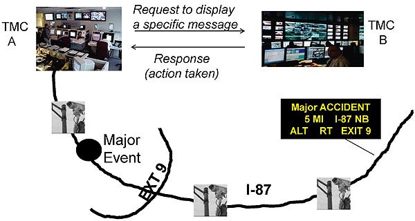
(Extended Text Description: Relevant descriptive information provided by author for this figure: : Something similar to above C2C concept in Slide 31 is taking place in this illustration as well, except in this case the purpose is different and more involved. The layout calls a requesting center shown on the left TMC A and the owning center-TMC B on the right. TMC B has a DMS on the roadway link in its jurisdiction NB. (In our example on the slide the roadway is designated as North-South, TMC B on north end, TMC A on south end). The illustration now begins with a request from TMC A on left in whose jurisdiction on the same roadway, an incident occurred and it was felt that if TMC B on right places a warning message that read “Major ACCIDENT 5 MI I-87 NB ALT RT EXIT 9” ahead of the event site near TMC A, motorists will be well-advised to Exit 9 which is way before event location. Point is made that motorists have a clear warning of a major accident on NB direction five miles ahead and they may decide to exit early North Bound, thus avoiding congested areas for a prolong period.)
Slide 33:
Summary of Learning Objective 2
Operational Needs
1. Reviewed operational and planning needs to support interagency communications
Slide 34:
Learning Objective #2
Summary
Operational Needs (cont.)
2. User needs categories:
2.3.1 Connection management
2.3.2 Support Authentication-Restrictions
2.3.3 Provide information on organizations
2.3.4 Share event information
2.3.5 Provide roadway network data
2.3.6 Provide control of devices
2.3.7 Share data for archiving
2.3.8 Accept null values
Slide 35:
Learning Objective #3
Volume I
Concept of Operations and Requirements
What is to be done?
Section 1 Document Introduction
Section 2 User Needs
Section 3 Requirements
Section 4 Traceability to National ITS Architecture
Section 5 NRTM (pages 174-295)
Slide 36:
Learning Objective #3
Volume II-Design Content
How is it to be done?
Section 1 Document Introduction
Section 2 TMDD Dialogs and Messages
Section 3 TMDD ISO 14817 ASN.1 and XML Data Concepts Definitions
Section 4 Requirement Traceability Matrix (RTM) (pages 58-635)ASN.1 and XML are Data Encoding Formats
Slide 37:
Learning Objective #3
Availability of Standardized Definitions by TMDD v3.0 standard
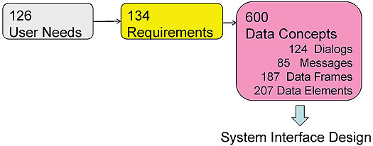
(Extended Text Description: Relevant descriptive information provided by author for this figure: There are three boxes in this slide. Boxes reads inventory of definitions supplied by the TMDD v3 standard: 126 user needs in first box, 134 requirements in second box. Last box has 600 design concepts, further broken down as 124 dialogs, 85 messages, 187 data frames and 207 data elements. An arrow flows from data concepts box to text that reads, system interface design.)
Slide 38:
Learning Objective #3
Understanding Relationship through NRTM and RTM
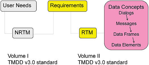
(Extended Text Description: Relevant descriptive information provided by author for this figure: The graphical layout has three boxes on first level, First box reads user needs, second reads requirements and third reads data concepts.
Second level shown few spaces below has two boxes: NRTM and other RTM separated by spaces. A solid line from input side of NRTM connects to User Needs box above and a solid line connects output side of NRTM to line Requirements box. NRTM thus depicts relationship between requirements and user needs. It shows that requirements exist because of user needs.
A second relationship is shown same way between Requirements and design concepts thru RTM box. This means that RTM connect every requirement to data concepts to be used for that requirement. So, this slide solidly depicts that: NRTM is a relationship between user needs and requirements and RTM is a relationship between requirements and design concepts. )
Slide 39:
Summary of Learning Objective 3
TMDD Structure
-
Provides NRTM for:
- Mapping operational needs to user needs definitions
- Tracing requirements to user needs
- With the NRTM, the relationships between user needs and requirements is standardized
Slide 40:
Learning Objective #3
Summary
TMDD Structure (cont.)
-
Provides RTM for:
- Tracing requirements to data concepts
- Relationship between requirements and data concepts (design) is standardized
- TMDD promotes "Off-the-shelf interoperability"
Slide 41:
Learning Objective #4
Where are User Needs located on "V"?
NRTM

(Extended Text Description: Relevant descriptive information provided by author for this figure: A graphic of the systems engineering process (SEP) is shown. The main graphic of the SEP is a V-shaped diagram with some additional horizontal “wings” on the left and right side of the top of the V. Starting from the left “wing” the steps are regional architecture, needs assessment, concept selection, project planning, and systems engineering management planning. At this point the steps begin to descend the left side of the V with concept of operations, system requirements, high-level design, detailed design, and software hardware and field installation. At this point the steps begin to ascend the right side of the V with unit device testing, subsystem verification, system verification and deployment, system validation, and operations and maintenance. At this point the steps are on the right “wing” of the V with changes and upgrades and retirement/replacement.
The following arrows supplement the figure:
- A time line at the bottom of the figure indicating that all steps proceed over time with the steps forming the V overlapping one another.
- A downward arrow on the left side of the V that indicates that these steps deal with decomposition and definition.
- An upward arrow on the right side of the V that indicates that these steps deal with integration and recomposition.
- A horizontal arrow near the bottom of the center of the V that connects the detailed design step to the unit testing step.
- A horizontal arrow a little higher that connects the subsystem requirements step with the subsystem verification step.
- A horizontal arrow a little higher that connects the system requirements step with the system verification step.
- A horizontal arrow near the top of the V that connects the concept of operations step with the system validation step.
Finally, major steps are separated by a barrier that is labeled “document approval.”
The slide has a circle drawn over high level design and detailed design and an arrow attached to a circle that is pointing to a side graphic shown with a title page of standards. This illustration shows that standards are located at high level and detailed design level of SEP life cycle. )
Slide 42:
Learning Objective #4
Parts of NRTM
What needs to be done - Details-specifics
User Needs - Requirements
|
UN ID |
User Need |
UN Selected |
Req. ID |
Req. |
Conformance |
Support |
Other Req. |
|---|---|---|---|---|---|---|---|
|
|
(Additional Formatting Notes for this slide: "What needs to be done" and "User Needs" are positioned over the first three columns on the table above. "Details-specifics" and "Requirements" are positioned above "Req. ID", "Req.", "Conformance", "Support", and "Other Req." Additional Notes from the Author: The graphic illustrates parts of NRTM, which is a table. In this slide a table with two rows and eight columns is shown. First row has headings for columns: UN ID, User need, UN selected, requirement ID, requirement, conformance, support and last column reads other requirement. The second row in this chart is empty, which will be filled-in by user at project level, for each user need.)
NRTM Structure has 8 Columns with Multiple Rows
Slide 43:
Learning Objective #4
NRTM Content
- Using the UN ID number (e.g. 2.3.6.4.5), the corresponding text from the standard allows you to determine if this UN is desired in your project.
|
UN ID |
User Need |
UN Selected |
Req. ID |
Req. |
Conformance |
Support |
Other Req. |
|---|---|---|---|---|---|---|---|
|
2.3.6.4.5 |
YES |
3.3.6.1.4.2 |
M |
YES |
(Additional Notes from the Author: Relevant descriptive information provided by author for this figure: The same layout is used as above in previous slide, except second row is now filled-in to show content nature. First column has entry 2.3.6.4.5, third column has YES, fourth column has entry 3.3.6.1.4.2 and conformance column has M, meaning Mandatory, followed by YES in support column.)
For Mandatory (M) requirements stated in the standard, project must select YES only.
For Optional requirements (O), project decides if the requirement will be used.
Slide 44:
Learning Objective #4
NRTM Role
-
With NRTM:
- Requirements are traced to user needs (at least one)
- Work is monitored at each stage of the system life cycle process (Are we addressing user need?)
- Final check to validate user needs is made (Did we build the right system?)
Slide 45:

Slide 46:
Learning Objective #4
Who do you think benefits from use of NRTM?
Type your response in the chat pod
Slide 47:
Learning Objective #4
Beneficiaries of NRTM

(Extended Text Description: Relevant descriptive information provided by author for this figure: There are four text boxes connected with a thin line. Starting with clockwise, there are requirements (The Specification Writer), risk management (The Integrator), capabilities (The Supplier) and interoperability (The User). Party concerned with each of this discussion point is shown in the parenthesis.)
Slide 48:
Learning Objective #4
Ensuring Interoperability
- User needs are a first step towards achieving C2C interoperability
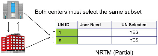
(Extended Text Description: Relevant descriptive information provided by author for this figure: The graphic on this slide include two centers with two separate arrows showing in-out process, next to which a table appears. One headed arrow to table is shown from each center. The arrows from centers rest with two rows of the table’s first column. This column shows user need 1 in first row and nth in the second row. This means that a subset of user needs from 1 to n is to be included in the specification by both centers to achieve interoperability. In summary for the slide, we must recognize that user needs are the first step to achieve interoperability and centers must include same set of user needs for this purpose.)
Slide 49:
Learning Objective #4
Understanding Mandatory User Needs
To conform to the standard, Mandatory user needs must be selected-YES
|
UN ID |
User Need |
UN Selected |
|---|---|---|
|
2.3.1.1 |
Verify Connection Active |
YES |
|
2.3.1.2 |
Request Needs to Support |
YES |
|
2.3.1.4 |
Need to Support Error Handling |
YES |
|
2.3.5.1.1 |
Need for Node Inventory |
YES |
|
2.3.5.1.2 |
Need for Link Inventory |
YES |
|
2.3.8 |
Need to Accept Null Values |
YES |
Ref. page 174, Volume I, Table 4, 4th Column UN Selected
(Additional Notes from the Author: A table with three columns and six rows outlines selected YES, all mandatory user needs. )
Slide 50:
Learning Objective #4
Understanding Optional User Needs
Select optional needs based on the project's operational needs
|
UN ID |
User Need |
UN Selected |
|---|---|---|
|
2.3.1.3 |
Need to Support Subscriptions |
Yes |
|
2.3.4.2 |
Need to Correlate an Event with Another Event |
Yes |
|
2.3.4.5 |
Need to Provide Multilingual Event Descriptions |
Yes |
|
2.3.4.6 |
Need for Current Event Information |
Yes |
|
2.3.6.1.3 |
Need to Share Detector Status |
Yes |
(Additional Notes from the Author: A table with three column and five rows outlines all optional user needs selected YES. )
Slide 51:
Learning Objective #4
Example
Centers must select same set of user needs for interoperability
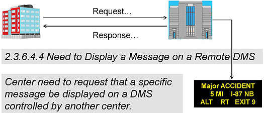
(Extended Text Description: Relevant descriptive information provided by author for this figure: This examples show a graphic with two centers with arrows from each going to other. The center that owns a DMS is shown on the right, with an arrow going to a DMS. The requesting center is on the left desiring to have a new message go on the DMS. The point of 2.3.6.4.4 user need is that for interoperability - this capability to request posting a message - both centers must select this user needs in their project NRTM. )
Slide 52:
Learning Objective #4
Preparing Project NRTM

(Extended Text Description: Relevant descriptive information provided by author for this figure: Same as Slide 38, Understanding Relationship thru NRTM and RTM. It also shows arrows flowing from User Needs to Requirements to Design concepts. NRTM and RTM graphic tables are empty. We need to learn to fill NRTM in this course. )
Slide 53:
Learning Objective #4
Preparing a Project NRTM
Step 1 Section 2 Volume I Page 22
Match project's operational need to User Need ID number and corresponding text description. This action determines if this UN is desired in your system
Example
2.3.6.4.5 Need to Verify DMS Control Status
The center that sends a request to display a specific message on a DMS operated by another center needs to confirm if the message was displayed. Possible statuses include that the message request was implemented, was queued, or was rejected.
DMS supports congestion (traffic) management
Slide 54:
Learning Objective #4
Preparing a Project NRTM (cont.)
Step 2
User Need Part
Write UN ID, UN and Select YES
Step 3
Requirements Part
Go to Section 5, Volume I, page 174, Table 4 to read allocated requirements
|
UN ID |
User Need |
UN Selected |
Req. ID |
Req. |
Conformance |
Support |
Other Req. |
|---|---|---|---|---|---|---|---|
2.3.6.4.5 |
Need to Verify DMS Control Status |
YES |
3.3.6.1.4.2 |
M |
YES |
(Additional Notes from the Author: Step 2 and 3 are shown above the table shown. The table is same as one in Slide 43, NRTM Content)
Slide 55:
Learning Objective #4
Project NRTM (Partially Populated)
Step 4
Find 2.3.6.4.5 on page 224
Read ten listed Req. in 4th column
10 requirements are allocated to a user need
|
UN ID |
User Need |
UN Selected |
Req. ID |
Requirement |
Conformance |
Support |
Other Req. |
|---|---|---|---|---|---|---|---|
|
2.3.6.4.5 |
Need to Verify DMS Control Status |
YES |
3.3.6.1.4.2 |
M |
Yes |
||
|
3.3.6.1.4.2.1 |
M |
Yes |
|||||
|
3.3.6.1.4.2.2.1 |
O |
Yes |
|||||
|
3.3.6.1.4.2.2.2 |
O |
Yes |
|||||
|
3.3.6.1.4.2.2.3 |
O |
Yes |
|||||
|
3.3.6.1.4.2.2.4 |
O |
Yes |
|||||
|
3.3.6.1.5.1 |
M |
Yes |
|||||
|
3.3.6.1.5.2 |
M |
Yes |
|||||
|
3.3.6.1.5.3 |
M |
Yes |
|||||
|
3.3.6.5.4 |
M |
Yes |
(Additional Formatting Notes for this Slide: The statement "10 requirements are allocated to a user need" appears directly over the columns, "Req. ID", "Requirement", "Conformance", "Support", and "Other Req.".) Additional Notes from the Author: Project NRTM (Partially Filled): Step 4 is shown with the same table as above, Slide 54. Last five columns on requirements are populated. NRTM is now shaping up with information in it.)
Slide 56:
Summary of Learning Objective 4
- User needs are located at ConOps stage on "V" diagram
- Using NRTM Operational Needs are mapped to user needs in Section 2, Volume I
- NRTM traces requirements to at least one user need
- Mandatory UN must be selected YES
- Optional UN, if selected YES, associated requirements are Mandatory
Slide 57:
Learning Objective #5
Pre-Arrangement
- How do we implement a System Interface?
- Pre-Arrangement

(Extended Text Description: Relevant descriptive information provided by author for this figure: The slide shows three centers, one on left and two on the right. They appear as triangle with arrows flowing out from each to others. Two of them operate 24/7, and one 9-5 M-F. This graphic adds a message that centers must agree ahead to make C2C process to work.)
Slide 58:

Slide 59:
Learning Objective #5
Name some pre-arrangements before a system interface is implemented
Type your response in the chat pod
Slide 60:
Learning Objective #5
Types of Agreements
Memorandum of Understanding (MOU)
Example: Florida DOT District Four
Purpose: This......MOU.....provides the framework to promote a collaborative effort to
.....promote coordinated decision-making and information sharing in planning, design, deployment, operations,.......
Maximize communications between and among the network of traffic management centers.......
Slide 61:
Learning Objective #5
Types of Agreements
Operational Agreement Covers:
- Networks (system admin.)
- Authentication, Security
-
Standard Operating Procedures (SOPs) for:
- Current conditions on road networks
- Sharing devices (DMS, CCTV,...)
- Sharing event Information (Traffic Incidents, emergency.. )
- Sharing data (Archiving)
Slide 62:
Learning Objective #5
Example: Agreement

7 Formal Agreements
The Sacramento Region ITS Partnership Memorandum of Understanding for Participation in the Regional ITS Deployment Strategy, although not a binding agreement, provides a framework for cooperation between key STARNET stakeholders, especially for sharing of regional funds.Source: https://www.fhwa.dot.gov/cadiv/segb/files/starnet/starnetstake.htm
Slide 63:
Learning Objective #5
Example
Puget Sound Regional Council
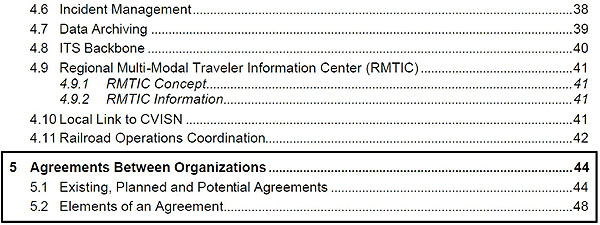
(Extended Text Description: Slide 63: This is an excerpt from the Puget Sound Regional Council. Here it references the listing of the following information:
4.6 Incident Management - 38
4.7 Data Archiving - 39
4.8 ITS Backbone - 40
4.9 Regional Multi-Modal Traveler Information Center (RMTIC) - 41
- 4.9.1 RMTIC Concept - 41
- 4.9.2 RMTIC Information - 41
4.10 Local Link to CVISN - 41
4.11 Railroad Operations Coordination - 42
The following listed items are boxed:
5 Agreements Between Organizations - 44
- 5.1 Existing, Planned and Potential Agreements - 44
- 5.2 Elements of an Agreement - 48)
Source: psrc.org/assets/543/regarch.pdf
Slide 64:
Learning Objective #5
TMDD's Relationships to Architecture

(Extended Text Description: Relevant descriptive information provided by author for this figure: The slide shows a graphic with 12 boxes. Solid lines are connecting these boxes to indicate data flows identified by the Architecture and supported by the TMDD v3 partially, which include boxes labeled: Information Service Provider*, Event Promoter, Maintenance and Construction Operations*, Weather Service*, Surface Transportation Weather Service, Emergency Management, Toll Administration*, Transit Management*, Archive Data Management*, and Media. TMC can support six data flows to other centers with an asterisk. There is a thin oval shown over External Traffic Management Center and Traffic Management Center.)
Slide 65:
Learning Objective #5
Example of TMDD's Support
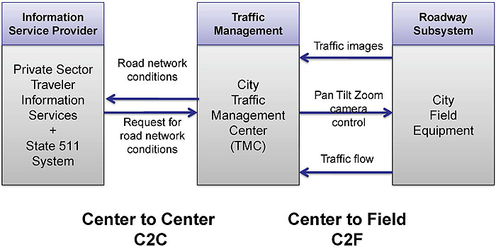
(Extended Text Description: Relevant descriptive information provided by author for this figure: Based on the previous slide discussion, this slide has graphic that illustrates a market package set up with three boxes shown vertically. One on left is titled Information Service Provider or ISP, Traffic Management Center in the middle and Roadway Subsystem on the right. ISP and TMC have two arrows between them and cover C2C data flows. TMC and Roadway have two data flows between them and one from roadway to TMC, together all three serve C2F needs. )
Slide 66:
Learning Objective #5
Related C2C Standards
SI Implementation Requires:
1. TMDD v3 standard:
- User Needs, Requirements and ISO 14817 Based Data Concepts
- Centers must have a common specification
2. Application Protocol:
- NTCIP 2306 C2C XML or NTCIP 2304 C2C DATEX
- Centers must select one as a common protocol for Interoperability
Slide 67:

Slide 68:
Case Study
TMC-A has 24/7 traffic management operations, which includes 50 traffic signals, 7 DMSs, and 15 CCTV cameras, and has received approval from FHWA to develop an ITS project to add a system interface capability to exchange information with the adjoining TMC B.
Both TMCs have agreed to coordinate traffic management in the region and share event information and field devices.
A system interface is to be procured soon. What Next?
Slide 69:

Slide 70:
Please type in response in the chat room
1. The project will be guided by the SEP to develop the system interface desired by the TMCs.
2. The TMDDv3.0 standard will be used to develop the system interface for both TMCs.
3. In this case study the Owning Center is TMC A and the External Center is TMC B.
Slide 71:
Please type in response in the chat room
4. Which tool will you use to map the operational need? NRTM
5. How do we go about preparing project user needs? PrepareProject NRTM
6. Both TMCs must prepare a specification common with same set of user needs, requirements and data concepts to achieve off-the-shelf interoperability.
Slide 72:
Case Study Exercise
7. The overall Operational Need driving this development can be stated as traffic (congestion) management
8. The standardized user needs definitions can be found in TMDD v3.0 standard, Volume I Section 2
9. Information exchange related user needs are: roadway network, event sharing , device sharing, and data archiving. Additional four are related to network authentication management etc.
Slide 73:
Case Study Exercise (Cont.)
10. What pre-arrangement should TMCs have in place for implementation of the SI? MOU-SOPs-Agreement
11. NTCIP 2306-C2C XML is selected as a common protocol to support the system interface.
Slide 74:
What did we learned today?
- TMDD addresses the need for system interface capability for C2C "information exchange" [LO #1]
- Supports eight categories of operational needs [LO #2]
-
Standardized definitions are available for use in a specification: [LO #3]
- Volume I contains User Needs and Requirements and NRTM
- Volume II contains design concepts and RTM
Slide 75:
What did we learned today? (cont.)
- Learned how to prepare a project NRTM [LO#4]
- Required pre-arrangement to implement a system interface [LO#5]
- The Case Study examination confirmed key concepts
- Prepared for the A321b module on the requirements
Slide 76:
Next Steps:
Module A321b
Specifying Requirements for Traffic Management Systems Based on TMDD v3 Standard
- Requirements and their link to Data Concepts through RTM will be discussed in details to complete preparation of a system interface specification
Slide 77:
Where to Find More Information
-
TMDD v3 standard and TMDD Guide:
http://www.ite.org/standards/distribution.asp
-
NTCIP Guide:
www.ntcip.org/library
-
Systems Engineering Guidebook for ITS FHWA-Caltrans, v3.0 2009:
https://www.fhwa.dot.gov/cadiv/segb/files/segbversion3.pdf
-
Systems Engineering for Intelligent Transportation Systems, FHWA, 2007:
http://ops.fhwa.dot.gov/publications/seitsguide/index.htm
Slide 78:
