Module 14 - A311b
A311b: Specifying Requirements for DMS Systems Based on NTCIP 1203 Standard v03
HTML of the PowerPoint Presentation
(Note: This document has been converted from a PowerPoint presentation to 508-compliant HTML. The formatting has been adjusted for 508 compliance, but all the original text content is included, plus additional text descriptions for the images, photos and/or diagrams have been provided below.)
Slide 1:
(Extended Text Description: Welcome - Graphic image of introductory slide. A large dark blue rectangle with a wide, light grid pattern at the top half and bands of dark and lighter blue bands below. There is a white square ITS logo box with words "Standards ITS Training - Transit" in green and blue on the middle left side. The word "Welcome" in white is to the right of the logo. Under the logo box is the logo for the U.S. Department of Transpotation, Office of the Assistant Secretary for Research and Technology.)
Slide 2:

(Extended Text Description: This slide, entitled "Welcome" has a photo of Ken Leonard, Director, ITS Joint Program Office, on the left hand side, with his email address, Ken.Leonard@dot.gov. A screen capture snapshot of the home webpage is found on the right hand side - for illustration only - from August 2014. Below this image is a link to the current website: www.its.dot.gov/pcb - this screen capture snapshot shows an example from the Office of the Assistant Secretary for Research and Development - Intelligent Transportation Systems Joint Program Office - ITS Professional Capacity Building Program/Advanced ITS Education. Below the main site banner, it shows the main navigation menu with the following items: About, ITS Training, Knowledge Exchange, Technology Transfer, ITS in Academics, and Media Library. Below the main navigation menu, the page shows various content of the website, including a graphic image of professionals seated in a room during a training program. A text overlay has the text Welcome to ITS Professional Capacity Building. Additional content on the page includes a box entitled What's New and a section labeled Free Training. Again, this image serves for illustration only. The current website link is: https://www.its.dot.gov/pcb.)
Slide 3:
A311b: Specifying Requirements for DMS Systems Based on NTCIP 1203 Standard v03
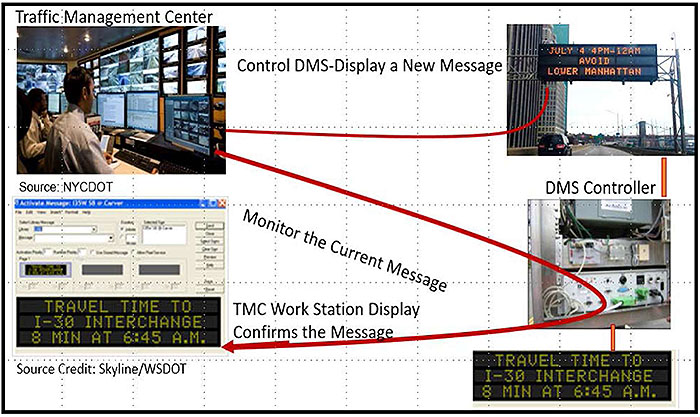
(Extended Text Description: Author's relevant description: Title slide: Specifying Requirements for DMS Systems Based on NTCIP 1203 Standard v03 - The slide graphic includes an image of a Traffic Management Center from NYC DOT on the left side-an operator is looking at work station with DMS images. Another image is shown at top right corner that actually shows DMS messages with travel times in minutes. An image at right side bottom shows a DMS controller installed in the field with door open. A software screenshot is shown below TMC image on left to indicate a message is confirmed. The entire slide graphics together conveys the meaning and purpose of this module and what is expected from DMS deployments. )
Slide 4:
Instructor

Raman K. Patel, Ph.D., P.E.
President
RK Patel Associates, Inc. New York City, NY, USA
Slide 5:
Learning Objectives
- Briefly Review the Structure of the DMS Standard
- Explain the Purpose of a Requirements Traceability Matrix (RTM) and Its Benefits
- Prepare a Project-Level RTM with Standard-Supplied Requirements and Design Content (Concepts)
- Prepare a DMS Specification (Checklist)
Slide 6:
Learning Objective 1
- Briefly Review the Structure of the Dynamic Message Sign (DMS) Standard
Slide 7:
What Is NTCIP 1203 v03?
DMS Communications Interface Standard

(Extended Text Description: Author's relevant description: DMS Communications Interface Standard - At bottom of the slide, a TMC management station is communicating with a connected line to a sign controller, which is connected to a DMS sign. The slide contains the following bullet items:
- Provides DMS user needs, requirements, and design content.
- Using this information, we can prepare a specification to build a Communications Interface.
)
Slide 8:
What Is NTCIP 1203 v03?
Recap of Updated Module A311a
- Reviewed DMS Operational Needs and the Protocol Requirements List (PRL), which outlined requirements
- Now we will discuss types of requirements
- Introduce Requirements Traceability Matrix (RTM) and how it is used

Slide 9:
Structure of Standard

(Extended Text Description: Author's relevant description: Information Needed to Prepare a DMS Specification - On the left side, a slanted text box shows CoOps, Requirements and Design sections, each is then connecting to right side text boxes with Section 2 User Needs, 3 Functional Requirements, 4 Dialogs, and 5 Management Information Base Objects, respectively with arrows coming from left side. This means that NTCIP 1203 v03 Part 1 offers information needed in three sections.)
Slide 10:
Structure of Standard
Specific Guidance from the NTCIP 1203 v03 Standard
Part 1: Provides Template for Selecting User Needs Called Project Requirements List (PRL)
Part 1: Annex A: Provides template for Design Dialogs, and Objects Called Requirements Traceability Matrix (RTM)
Part 2: Annex C: Outlines Test Procedures for a DMS Test Plan

Slide 11:
What Is a Requirement?
"A statement that identifies a system, product, or process' characteristic or constraint, which is unambiguous, clear, unique, consistent, stand-alone (not grouped), and verifiable and is deemed necessary for stakeholder acceptability."
- INCOSE Systems Engineering Handbook

Slide 12:
What Is a Requirement?
Definition of a Requirement
"A requirement describes a condition or capability to which a system must conform; either derived directly from user needs, or stated in a contract, standard, specification, or other formally imposed document. A desired feature, property, or behavior of a system." NTCIP 1203 v03
Example of a DMS Requirement
3.5.2.3.3.3 Define a Message
The DMS shall allow a management station to download a message for storage in the sign controller's message library.
Slide 13:
Standard Structure
Types of DMS Requirements
3.4 Architectural Requirements
- Support Basic Communications
- Support Logged Data
- Manage Access
3.5 Data Exchange Requirements
- Manage the DMS Configuration
- Control the DMS
- Monitor the Status of the DMS
- Providing for Multi-Version Interoperability
3.6 Supplemental Non-Communications Requirements

Slide 14:
Review Standard Structure
Architectural Requirements
Define the required behavior of the system in exchanging data across the communications interface
3.4 Architectural Requirements
- Support Basic Communications
- Support Logged Data
- Manage Access

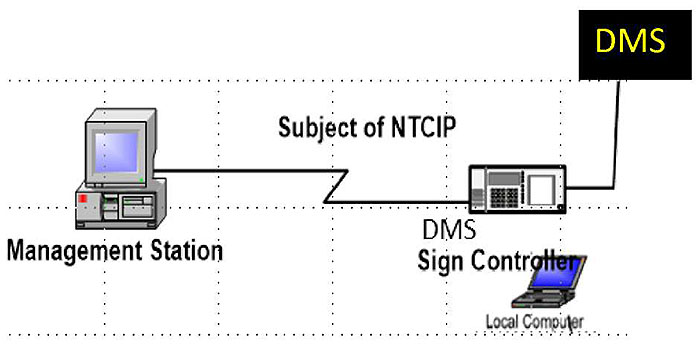
(Extended Text Description: Author's relevant description: An image of a Management Station is shown connected to DMS sign controller which in turn connects to a DMS sign. An arrow points to the connection with the text Subject of NTCIP.)
Slide 15:
Standard Structure
Architectural Requirements (Section 3.4)
3.4.2.3 Retrieve Logged Data
The DMS shall allow a management station to retrieve data from the event log.
3.4.2.4 Clear Log
The DMS shall allow the management station to clear log entries of a given event class that are less than or equal to a given time.
3.4.4.1 Determine Current Access Settings
The DMS shall allow the administrator at the management station to determine the current access settings.

(Extended Text Description: Author's relevant description: Example - Same as above slide 14, showing the connection between a Management Station and DMS sign controller.)

Slide 16:
Standard Structure
Data Exchange Requirements (Section 3.5)
Define the required behavior of the system in exchanging data across the communications for three major areas:
3.5.1 Manage the DMS Configuration
3.5.2 Control the DMS
3.5.3 Monitor the Status of the DMS


Slide 17:
Standard Structure
Data Exchange Requirements (Section 3.5)
-
3.5.1 Managing Configuration
- Identify DMS - sign type and technology
-
3.5.1.1.1 Determine Sign Type and Technology
- The DMS shall allow a management station to determine its type and technology.
-
3.5.1.2 Determine message capabilities
- Determine basic message capabilities - size, beacons, access
- Determine matrix capabilities - sign face size and character size in pixels, pixel spacing

Slide 18:
Standard Structure
Examples of Data Exchange Requirement (Section 3.5)
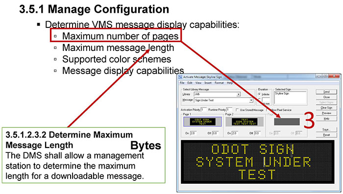
(Extended Text Description: Author's relevant description: Example - A screen shot of a TMC software is shown at right-bottom corner. Additional text on the slide shows a box of text at the bottom left connected to the bullet item "Maximum number of pages", then connected to the screen shot. The box at the bottom contains the text: "3.5.1.2.3.2 Determine Maximum Message Length The DMS shall allow a management station to determine the maximum length for a downloadable message." The bulleted list is as follows:
3.5.1 Manage Configuration
-
Determine VMS message display capabilities:
- Maximum number of pages
- Maximum message length
- Supported color schemes
- Message display capabilities
)
Slide 19:
Standard Structure
Data Exchange Requirements (Section 3.5)
3.5.1 Manage Configuration
-
Manage Fonts - Determine maximum number of:
- Fonts supported
- Character size
- Characters per font
- Retrieve a font definition
- Configure a font, delete a font, validate a font
- Manage Graphics Details - Determine maximum number of graphics and their size and other details


Slide 20:
Standard Structure
Examples of Data Exchange Requirements (Section 3.5)
3.5.2 Control the DMS
3.5.2.1 Manage Control Source
A DMS shall allow the user to switch between the local and central control modes.
- Reset the sign controller
-
Control the sign face:
- Activate a message
- Manage default message display parameters
- Manage message library, schedule messages for display, configure event-based message activation
Slide 21:
Standard Structure
Example of a Requirement for Scheduling a Message
3.5.2.3.4.1 Retrieve a Schedule: The DMS shall allow a Management station to retrieve the schedule as stored within the sign controller.
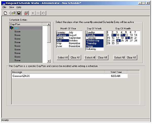
Management Station
If an event is known in advance, a message can be scheduled to run between a set time and date.

Sign Controller
Source: WSDOT
Slide 22:
Standard Structure
Examples of Data Exchange Requirements (Section 3.5)
3.5.3 Monitor the Status of the DMS
-
Perform diagnostics:
- Test operational status of DMS components
- Provide general DMS error status information
- Identify problem subsystems
- Monitor subsystems status details such as pixel errors, light sensor errors
- Monitor the current message - Monitor information about the current message
- Monitor status of DMS control functions

Slide 23:
Standard Structure
Monitor the Status of the Current Message

Slide 24:
Standard Structure
Support for Maintenance Requirements

(Extended Text Description: Author's relevant description: Example: A screenshot shows maintenance requirements. Diagnostics and Troubleshooting can be performed with central system that contains numerous maintenance tools used for troubleshooting sign failures. Pop-up Examples are shown in the text box, such as Light Sensor readings, Temp Sensor readings, Power Supply Pass/Fail readings, etc.)
Source: WSDOT

Slide 25:
Standard Structure
Supplemental Requirements (Section 3.6)
Supplemental Requirements are additional requirements not covered by the other two categories (Architectural/Data exchange).
Example: Include range capabilities of the DMS:
- How many messages a VMS is required to support?

Slide 26:
Standard Structure
Types of DMS Requirements Supported (Section 3.6)
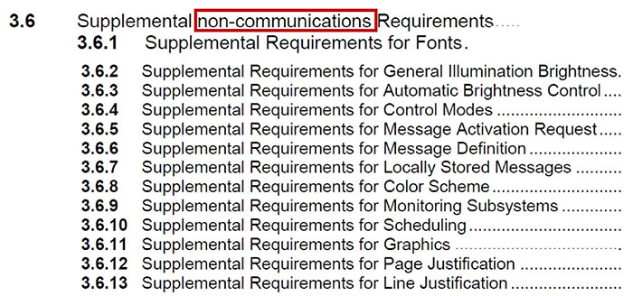
(Extended Text Description: Types of DMS Requirements Supported (Section 3.6) are shown below, with the words "non-communications" highlighted in red:
3.6 Supplemental non-communications Requirements.....
3.6.1 Supplemental Requirements for Fonts.
3.6.2 Supplemental Requirements for General Illumination Brightness.
3.6.3 Supplemental Requirements for Automatic Brightness Control....
3.6.4 Supplemental Requirements for Control Modes...........................
3.6.5 Supplemental Requirements for Message Activation Request.....
3.6.6 Supplemental Requirements for Message Definition....................
3.6.7 Supplemental Requirements for Locally Stored Messages..........
3.6.8 Supplemental Requirements for Color Scheme............................
3.6.9 Supplemental Requirements for Monitoring Subsystems.............
3.6.10 Supplemental Requirements for Scheduling.................................
3.6.11 Supplemental Requirements for Graphics....................................
3.6.12 Supplemental Requirements for Page Justification......................
3.6.13 Supplemental Requirements for Line Justification........................
)

Slide 27:
Standard Structure

(Extended Text Description: Author's relevant description: This slide highlights supplemental requirements with familiar types for signs used in photos, both are font issues. An arrow points from the text "the number of fonts" to the table below, "The DMS shall support at least ____ fonts":
Illustration of a Supplemental Requirement
3.6.1.1 Support for a Number of Fonts
The DMS shall support the number of fonts as defined by the specification. If the specification does not define the number of fonts, the DMS shall support at least one font.
3.3.4 Protocol Requirements List - Supplemental Table
| Req ID | Requirement | Req ID | Requirement | Conformance | Support | Additional Specifications |
|---|---|---|---|---|---|---|
| Supplemental Requirements | ||||||
| 3.6.1 | Supplemental Requirements for Fonts | |||||
| 3.6.1.1 | Support for a Number of Fonts | M | Yes | The DMS shall support at least ____ fonts (1..255). NOTE: The specification may optionally specify the fonts to be stored in the sign controller upon initial delivery by using an additional attached sheet to define the desired pixel-by-pixel bitmaps of each character of each font, | ||
)
Slide 28:
Standard Structure
Types of Standardized Dialogs Used to Manage DMSs (Section 4)
Dialogs are sequence of data exchanges that fulfill various requirements to communicate to a DMS system:
G.1 Generic SNMP GET Interface to retrieve data from DMS
G.2 Generic SNMP GET-NEXT Interface defines a process by which a management station can explore data within a device to fulfill the requirements
G.3 Generic SNMP SET Interface defines a generic process by which a management station can send data to a device
Slide 29:
Standard Structure
Illustration of a Generic SET Dialog
G.3 GENERIC SNMP SET INTERFACE
SNMP defines a generic process by which a management station can send data to a device. This process consists of a Set request and a GetResponse (sic) as depicted in Figure 14. Both the Set request and the GetResponse messages contain a list of objects as defined by the varBindingList structure (see Annex G.4).
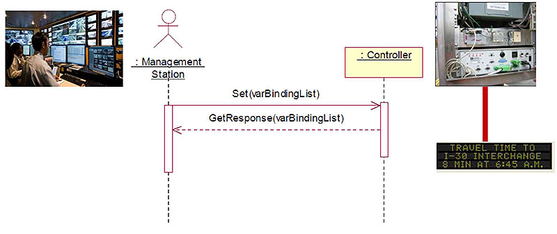
Figure 14 SNMP Set Interface
Slide 30:

Slide 31:
Question
Which of the following is a FALSE statement
related to the DMS Standard?
Answer Choices
- Supports configuration, control, and monitoring of DMS functions
- Supplemental requirements directly involve communications between the management station and the DMS
- Supports remote communications to the DMS Controller
- Standardized dialogs carry messages between two ends
Slide 32:
Review of Answers
 b) Supplemental requirements directly involve communications between the management station and the DMS
False statement. Supplemental requirements cover range values such as message line justification shown below.
3.6.13.2 Support Center Line Justification
The DMS shall support center line justification.
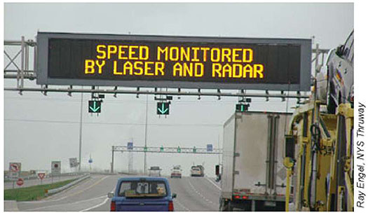
3.6.13.1 Support Left Line Justification
The DMS shall support left line justification.

Slide 33:
Review of Answers
 a) Supports configuration, control and monitoring of DMS functions
Correct statement. These are core functions of the DMS standard.
 c) Supports remote communications to DMS Controller
Correct statement. This statement is true. The standard supports the DMS communications interface.
 d) Standardized dialogs carry messages between two ends
Correct statement. This statement is true. DMS has three dialogs: G. 1, G.2, and G.3 to facilitate remote conversations.
Slide 34:
Learning Objectives
- Briefly Review the Structure of the DMS Standard
- Explain the Purpose of a Requirements Traceability Matrix (RTM) and Its Benefits
Slide 35:
Learning Objective 2
- Explain the Purpose of a Requirements Traceability Matrix (RTM) and Its Benefits
Slide 36:
What Is an RTM?
Revisiting Protocol Requirements List (PRL): Module A311a
PRL table traces User Needs to Requirements
| USER NEED SECTION NUMBER | USER NEED | FR SECTION NUMBER | FUNCTIONAL REQUIREMENT | CONFORMANCE | SUPPORT / PROJECT REQUIREMENT | ADDITIONAL PROJECT REQUIREMENTS |
|---|---|---|---|---|---|---|
| 2.5 | Features | M | Yes | |||
| 2.5.1 | Manage the DMS Configuration | M | Yes | |||
| 2.5.1.1 | Determine the DMS Identity | M | Yes | |||
| 3.5.1.1.1 | Determine Sign Type and Technology | M | Yes | |||
| H.2.1 | Determine Device Component Information | M | Yes | |||
| H.2.4 | Determine Supported Standards | M | Yes | |||
| 2.5.1.2 | Determine Sign Display Capabilities | 0 | Yes/ No | |||
| 3.5.1.2.1.1 | Determine the Size of the Sign Face | M | Yes | |||
Standardized DMS user needs are provided in Section 2 and requirements in Section 3 of v03 standard.

Slide 37:
What Is an RTM?
Terminology
- Traceability is defined as the ability to follow or study the logical progression among the needs, requirements, and design details in a step-by-step fashion
- Requirements Traceability Matrix (RTM) is a table that provides a complete design (dialogs and objects) for each requirement. The user has no role
| FR Section Number | Functional Requirement | Dialog ID | Object Section Number | Object | Additional Specifications |
|---|---|---|---|---|---|
| 3.5.1.1 | Identify DMS | ||||
NTCIP 1203 v03 Annex A, Page 233

Slide 38:
What Is an RTM?
Example of a DMS Requirement
"Determine Sign Type and Technology" is traced to dialog G.1 and associated design objects - 5.2.2 and 5.2.3

(Extended Text Description: Author's relevant description: The example of a requirement with associated design elements is shown and the traceability aspect is stressed. Example: RTM is shown with Traceability pointing to FR, G1 and Objects with individual arrows.
Traceability
| FR Section Number | Functional Requirement | Dialog ID | Object Section Number | Object | Additional Specifications | |
|---|---|---|---|---|---|---|
| 3.5,1.1 | Identify DMS | |||||
| 3.5.1.1.1 | Determine Sign Type and Technology | G.1 | ||||
| 5.2.2 | dmsSignType | |||||
| 5.2.9 | dmsSignTechnology | |||||
)

Slide 39:
What Is an RTM?
Value of Design Content Provided by the RTM

(Extended Text Description: Author's relevant description: This slide makes key points on value-added content of an RTM. Use of an RTM leads to conformant Interface. Image is shown same as one in slide 14 with the following bullet items. The word Interface from the first bullet points to the image:
- RTM presents the standardized Designcontent to build the DMS Communications Interface
-
Interface will be conformant to standard ONLY if:
- Each functional requirement is implemented with all Objects and Dialogs traced from that requirement given by the RTM.
- Management Station implements all Dialogs traced from the functional requirement.
)

Slide 40:
Parts of RTM with DMS Examples
Parts of RTM Table
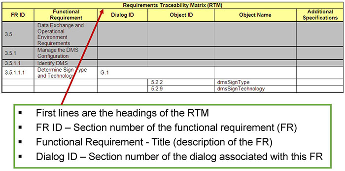
(Extended Text Description: Author's relevant description: Parts of RTM: An RTM table is shown with a text box pointing to first row which shows columns of RTM.
| Requirements Traceability Matrix (RTM) | |||||
| FR ID | Functional Requirement | Dialog ID | Object ID | Object Name | Additional Specifications |
|---|---|---|---|---|---|
| 3.5 | Data Exchange and Operational Environment Requirements | ||||
| 3.5.1 | Manage the DMS Configuration | ||||
| 3.5.1.1 | Identify DMS | ||||
| 3.5.1.1.1 | Determine Sign Type and Technology | G.1 | |||
| 5.2.2 | dmsSignType | ||||
| 5.2.9 | dmsSignTechnology | ||||
The text box contains the following bulleted items:
- First lines are the headings of the RTM
- FR ID - Section number of the functional requirement (FR)
- Functional Requirement - Title (description of the FR)
- Dialog ID - Section number of the dialog associated with this FR
)
Slide 41:
Parts of RTM with DMS Examples
Parts of RTM Table
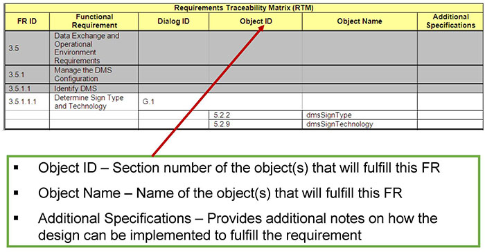
(Extended Text Description: A text box with bulleted items points to the Object ID column of the same table as Slide 40:
- Object ID - Section number of the object(s) that will fulfill this FR
- Object Name - Name of the object(s) that will fulfill this FR
- Additional Specifications - Provides additional notes on how the design can be implemented to fulfill the requirement
)
Slide 42:
Parts of RTM with DMS Examples
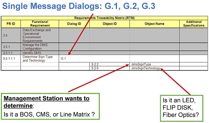
(Extended Text Description: Author's relevant description: Single Message is referenced with Generic G.1, G.2 and G.3 Dialogs. The Requirements Traceability Matrix (RTM) presented in Annex A identifies the standardized dialog that can be used to achieve each of the data exchange requirements defined in Section 3.5. Simple data exchange requirements reference one of the generic SNMP dialogs along with a list of data elements. These equate to a single message being sent (e.g., a GET request) containing the referenced data elements followed the appropriate response per the generic dialog specification. Single message dialog is shown with arrow to G1 in RTM and objects from bottom text box, to the same table as Slide 40.)
Slide 43:
Parts of RTM with DMS Examples
More Complicated Data Exchange Requires Specified Dialogs (Section 4)
Example: Activate a Message

(Extended Text Description: Author's relevant description: SPECIFIED DIALOGS-This section provides the standardized data exchange sequences that can be used by management stations to ensure interoperable implementations for the various data exchange requirements identified in Section 3.4. Diagrams and graphical representations are included to supplement the text (i.e., not used as a replacement for the text). This section only includes dialogs that have special semantics or impose special restrictions on the operations that are allowed. Example: RTM is shown with Dialog 4.2.3.1 with an arrow pointing in RTM with associated objects in the following table:
| Requirements Traceability Matrix (RTM) | |||||
| FR ID | Functional Requirement | Dialog ID | Object ID | Object Name | Additional Specifications |
|---|---|---|---|---|---|
| 3.5.2.3 | Control the Sign Face | ||||
| 3.5.2.3.1 | Activate a Message | 4.2.3.1 | |||
| 5 7.3 | dmsActivateMessage | ||||
| 5.11.2.1.1 | shortErrorStatus | ||||
| 5.7.17 | dmsActivateMsgError | ||||
| 5.7.24 | dmsActivateErrorMsgCode | ||||
| 5.7.18 | dmsMultiSyntaxError | ||||
| 5.7.19 | dmsMultiSyntaxError Position | ||||
| 5.7.20 | dmsMultiOtherErrorDescription | ||||
Dialog 4.2.3.1 fulfils the requirement using these objects.)

Slide 44:
Parts of an RTM with DMS Examples
Special Note on Importance of Dialogs Order
- Data exchange order is important, unless the dialogs state otherwise
- Interoperability may be compromised if the sequence of data exchanges is changed
- Conformance to standard may not be realized
If you are a system developer, these issues are bound to come up in your work.
Slide 45:
Benefits of RTM to Shareholders

(Extended Text Description: Author's relevant description: DMS stakeholders are many, and each has a stake in a successful DMS implementation. Image shown in slide 14 is shown here at bottom, indicating What between Management station and DMS controller-means What is being communicated.
Beneficiary of RTM Uses
- Procuring Agency-DMS Specification is connected to Are we missing something?
- Traffic Management Center-Operations is connected to Will the interface support operations?
- System Developers-Implementers is connected to Do I have to do it all over again?
- DMS Manufacturers/Vendors is connected to How do I know what their requirements are?
- Conformance Testers is connected to What do I test for conformance and why?
)
Slide 46:
Benefits of RTM to Shareholders
Benefits of RTM to Agency Procurement-Specification Preparation
- Standardized design is provided to users
- RTM will enable DMS Testing Process at later stage
- RTM enables interoperability, conformity, and incremental procurement
- Brings all parties to a common understanding, removes ambiguities

Source: NYCDOT-Patel
Slide 47:
Benefits of RTM to Shareholders
Benefits of RTM to System Developers/Implementers
- RTM reduces design work
- RTM's powerful traceability maintains order for interoperability, makes it easier to build a central system
- The protocol implementer uses RTM as a checklist to reduce the risk of failure to conform to NTCIP 1203 v03 through oversight

Slide 48:
Benefits of RTM to Shareholders
Benefits of RTM to DMS Vendors
- Vendor knows unambiguously what the users' requirements are, details of capabilities desired
- RTM ensures in-house product functionality testing prior to shipping to client
- Overall, legal disputes can be further avoided knowing what clients desire
Slide 49:
Benefits of RTM to Shareholders
The Market Place

(Extended Text Description: Author's relevant description: The Market Place is shown with two maps: this first one shows a region with multiple DMS sign manufacturers such as Daktronics, Telnet etc.; Bullet items include:
- Multiple Vendors
- Multiple Agencies
- Range of Products
)
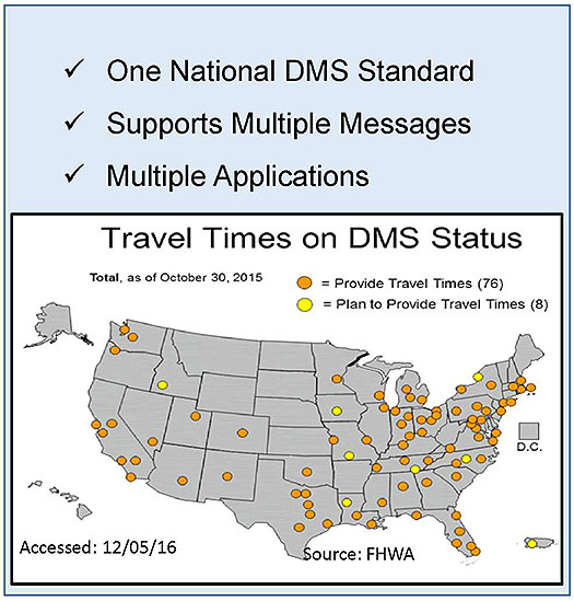
(Extended Text Description:Author's relevant description: The Market Place is shown with two maps: this second one shows a US map with locations where DMSs are deployed; Bullet items include:
- One National DMS Standard
- Supports Multiple Messages
- Multiple Applications
)
Slide 50:

Slide 51:
Question
Which of the following is a FALSE statement as it is applied to DMS?
Answer Choices
- RTM provides the standardized design content
- Generic Dialogs are used for single message to and from a DMS Controller
- Testing process uses RTM to verify each DMS requirement
- RTM does not reference dialog
Slide 52:
Review of Answers
 a) RTM provides the standardized design content
Correct statement. It reflects what RTM is about. For each requirement, a full design is provided.
 b) Generic Dialogs are used for single message to and from a DMS Controller
Correct statement. G. 1, G.2 and G.3 generic dialogs are meant for simple-single conversations between two ends.
 c) Testing process uses RTM to verify each DMS requirement
Correct statement. RTM is used in preparing Test Cases during testing process to test a requirement.
 d) RTM does not reference dialog
False statement. RTM specifies the order in which dialogs must be implemented in order to make error-free communications possible and to achieve interoperability.
Slide 53:
Learning Objectives
- Briefly Review the Structure of the DMS Standard
- Explain the Purpose of a Requirements Traceability Matrix (RTM) and its Benefits
- Prepare a Project-Level RTM with Standard-Supplied Requirements and Design Content (Concepts)
Slide 54:
Learning Objective 3
- Prepare a Project-Level RTM with Standard-Supplied Requirements and Design Content (Concepts)
Slide 55:
Review a Step to Continue with Requirements from PRL
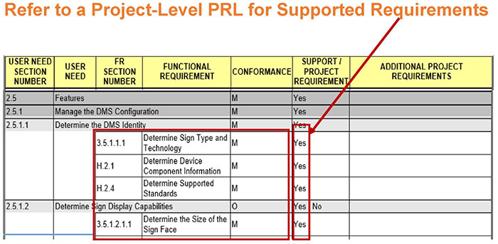
(Extended Text Description: Author's relevant description: Refer to PRL: A PRL table with a box highlighting Requirements is shown and Support column-means these requirements are Mandatory M and must be selected YES in the support column. The table is shown below with requirements highlighted in red:
Refer to a Project-Level PRL for Supported Requirements
| USER MEED SECTION NUMBER | USER NEED | FR SECTION NUMBER | FUNCTIONAL REQUIREMENT | CONFORMANCE | SUPPORT/ PROJECT REQUIREMENT | ADDITIONAL PROJECT REQUIREMENTS |
|---|---|---|---|---|---|---|
| 2.5 | Features | M | Yes | |||
| 2.5.1 | Manage the DMS Configuration | M | Yes | |||
| 2.5.1.1 | Determine the DMS Identity | M | Yes | |||
| 3.5.1.1.1 | Determine Sign Type and Technology | M | Yes | |||
| H.2.1 | Determine Device Component Information | M | Yes | |||
| H.2.4 | Determine Supported Standards | M | Yes | |||
| 2.5.1.2 | Determine Sign Display Capabilities | 0 | Yes /No | |||
| 3.5.1 2 1 1 | Determine the Size of the Sign Face | M | Yes | |||
)
See Student Supplement for Module A311a for a Project PRL Example

Slide 56:
Complete Project RTM with Entries (Populating Table) for Dialogs/Design Concepts
RTM Provides the Design for Each Supported Requirement
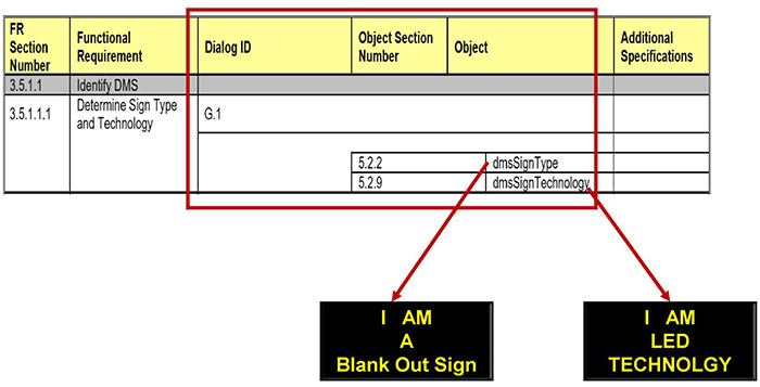
(Extended Text Description: Author's relevant description: RTM Provides the Design: RTM table is shown with box over Dialog-Object columns. A text box points I am a Blank Out Sign, another point to I am LED Technology. Both are related to objects shown with arrows. The table is shown below:
| FR Section Number | Functional Requirement | Dialog ID | Object Section Number | Object | Additional Specifications | |
|---|---|---|---|---|---|---|
| 3.5,1.1 | Identify DMS | |||||
| 3.5.1.1.1 | Determine Sign Type and Technology | G.1 | ||||
| 5.2.2 | dmsSignType | |||||
| 5.2.9 | dmsSignTechnology | |||||
)
Slide 57:
Examples of RTM

(Extended Text Description: Author's relevant description: Example: same as above RTM tables is shown with box covering requirement column and objects column. The table is shown below:
Message Display Capabilities-Manage Configuration (3.5.1)
| FR Section Number | Functional Requirement | Dialog ID | Object Section Number | Object | Additional Specifications | |
|---|---|---|---|---|---|---|
| 3.5.1.2.3 | Determine VMS Message Display Capabilities | |||||
| 3.5.1.2.3.1 | Determine Maximum Number of Pages | G.1 | ||||
| 5.5.24 | dmsMaxNumberPages | |||||
| 3.5.1.2.3.2 | Determine Maximum Message Length | G.1 | ||||
| 5.5.25 | dmsMaxMultiStringLength | |||||
| 3.5.1.2.3.3 | Determine Supported Color Schemes | G.1 | ||||
| 5.5.22 | dmsColorScheme | |||||
| 5.3.7 | monochromeColor | |||||
| 3.5.1.2.3.4 | Determine Message Display Capabilities | G.1 | ||||
| 5.5.23 | dmsSupportedMultiTags | |||||
| 3.5.1.2.4 | Delete All Messages of a Message Type with One Command | G.3 | ||||
| 5.7.16 | dmsMemoryMgmt | |||||
)
Slide 58:
Examples of RTM
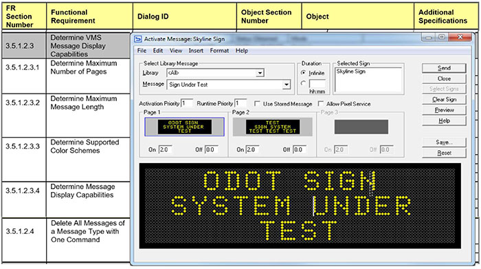
Display Capabilities Requirements Are Fulfilled
Slide 59:
Examples of RTM
Reset the Sign Controller-Manage Control (3.5.2)
| FR Section Number | Functional Requirement | Dialog ID | Object Section Number | Object | Additional Specifications | |
|---|---|---|---|---|---|---|
| 3.5.2.2 | Reset the Sign Controller | G.3 | ||||
| 5.7.2 | dmsSWReset | |||||
3.5.2.2 Reset the Sign Controller
The DMS shall allow a management station to reset the sign controller.

(Extended Text Description: Author's relevant description: RTM table is shown, with an image under 3.5.2.2 Reset the Sign Controller requirement. The image shows a TMC talking to a DMS sign controller with two-headed red arrow in between.)

Slide 60:
Examples of RTM
| Requirements Traceability Matrix (RTM) | |||||
| FR ID | Functional Requirement | Dialog ID | Object ID | Object Name | Additional Specifications |
|---|---|---|---|---|---|
| 3.5.3 | Monitor the Status of the DMS | ||||
| 3.5.3.1 | Perform Diagnostics | ||||
| 3.5.3.1.1 | Test Operational Status of DMS Components | ||||
| 3.5.3.1.1 1 | Execute Lamp Testing | 4.2.4.1 | |||
| 5.11.2.5.3 | lampTestActivation | ||||
| 3.5.3.1.1.2 | Activate Pixel Testing | 4.2.4.2 | |||
| 5.11.2.4.3 | pixelTestActivation | ||||


Slide 61:
Examples of RTM
Monitor Status-Manage Control (3.5.3)
| Requirements Traceability Matrix (RTM) | |||||
| FR ID | Functional Requirement | Dialog ID | Object ID | Object Name | Additional Specifications |
|---|---|---|---|---|---|
| 5.11.2.6.2 | clmsDrumNumRows | ||||
| 3.5.3.1.3.1 0 | Monitor Door Status | G.1 | |||
| 5.11.1.6 | dmsStatDoorOpen | ||||
3.5.3.1.3.10 (Monitor Door Status
The DMS shall allow a management system to determine which doors of the DMS are open or closed.


Slide 62:
Examples of RTM
Monitor Current Status of a Message-Manage Control
| FR Section Number | Functional Requirement | Dialog ID | Object Section Number | Object | Additional Specifications | ||
|---|---|---|---|---|---|---|---|
| 3.5.3.2 | Monitor the Current Message | ||||||
| 3.5.3.2.1 | Monitor Information about the Currently Displayed Message | 4.2.4.14 | |||||
| 5.8.5 | dmslllumBrightLevelStatus | ||||||
| 5.8.9 | dmslllumLightOutputStatus | ||||||
| 5.6.8.1 | dmsMessageMemoryType | Value of '5' only | |||||
| 5.6.8.2 | dmsMessageNumber | Value of '1' only | |||||
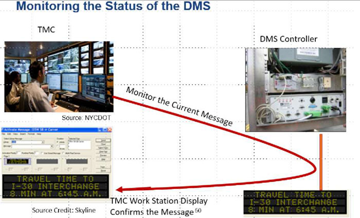
(Extended Text Description: Author's relevant description: Monitoring the Status of the DMS - This slide brings up how we monitor a sign status and perform diagnostics. Four phots are used. A TMC on upper left corner is shown communicate with a DMS controller in the field that is connected to a DMS sign at left bottom with a message: travel time to... This message is confirmed at TMC software driven-display on workstation at TMC. This shows how a message is monitored at TMC with conformation.)

Slide 63:
Examples of RTM
Architectural Requirements (3.4.2)
| Requirements Traceability Matrix (RTM) | |||||
| FRID | Functional Requirement | Dialog ID | Object ID | Object Name | Additional Specifications |
|---|---|---|---|---|---|
| 3.4.2.3 | Retrieve Logged Data | H.3.1.3 | |||
| 1103 v02 A.7.3.5 | eventClassNumRowslnLog | ||||
| 1103 v02 A.7.3.6 | eventClassNumEvents | ||||
| 1103 v02 A.7.7.1 | eventLogClass | ||||
| 1103 v02 A.7.7.2 | eventLogNumber | ||||
| 1103 v02 A.7.7.3 | eventLoglD | ||||
| 1103 v02 A.7.7.4 | eventLogTime | ||||
| 1103 v02 A.7.7.5 | eventLogValue | ||||
| 3.4.2.4 | Clear Log | G.3 | |||
| 1103 v02 A.7.3.3 | eventClassClearTime | ||||

(Extended Text Description: Author's relevant description: This slide provides an example of architectural requirement, Retrieve Logged Data using Dialog H.3.1.3, which is derived from NTCIP 1103 v02 standard. Support Operational Environment with Logged Data exchange - Same as above except communication is to the DMS controller for logged data inquiry. Additional text on this slide: When Connection is Broken or Using Dial-UP Connection: Logged-Data is retrieved at latertime when a broken connection is restored.)

Slide 64:

Slide 65:
Question
Which of the following statements does NOT apply to RTM?
Answer Choices
- RTM includes Architectural Requirements to communicate with sign controller
- Includes DMS user needs
- Includes dialogs and objects
- RTM lists requirements for retrieving data from a remote DMS
Slide 66:
Review of Answers
 a) RTM includes Architectural requirements to communicate with sign controller
Incorrect answer. The statement is valid. Architectural requirements make interface operational.
 b) Includes DMS user needs
Correct! This statement does not apply to RTM since user needs are part of only PRL.
 c) Includes dialogs and objects
Incorrect answer. Dialogs and objects for each requirement are provided in RTM.
 d) RTM lists requirements for retrieving data from a remote DMS
Incorrect answer. Retrieving data from a DMS is a data exchange function which is included in the RTM.
Slide 67:
Learning Objectives
- Briefly Review the Structure of the DMS Standard
- Explain the Purpose of a Requirements Traceability Matrix (RTM) and Its Benefits
- Prepare a Project-Level RTM with Standard-Supplied Requirements and Design Content (Concepts)
- Prepare a DMS Specification (Checklist)
Slide 68:
Learning Objective 4
- Prepare a DMS Specification (Checklist)
Slide 69:
DMS Specification Communications Interface Specification (NTCIP)
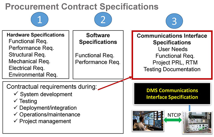
(Extended Text Description: Author's relevant description: Procurement Contract Specifications - At bottom right a DMS is shown pointing to sign controller and a TMC Talking to DMS controller. An arrow points to a text box on upper right side. Procurement Contract Specifications text:
1 - Hardware Specifications
Functional Req.
Performance Req.
Structural Req.
Mechanical Req.
Electrical Req.
Environmental Req.
2 - Software Specifications
Functional Req.
Performance Req.
Contractual requirements during:
- System development
- Testing
- Deployment/integration
- Operations/maintenance
- Project management
3 - Communications Interface Specifications
User Needs
Functional Req.
Project PRL, RTM
Testing Documentation
)
Slide 70:
DMS Specification Communications Interface Specification (NTCIP)
Building Communications Interface Specifications
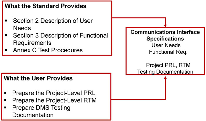
(Extended Text Description: Author's relevant description: Two text boxes with bulleted text on left are shown connected with arrows into a text box on right middle: Communications Interface Specifications, text below:
What the Standard Provides
- Section 2 Description of User Needs
- Section 3 Description of Functional Requirements
- Annex C Test Procedures
What the User Provides
- Prepare the Project-Level PRL
- Prepare the Project-Level RTM
- Prepare DMS Testing Documentation
Communications Interface Specifications
User Needs Functional Req.
Project PRL, RTM Testing Documentation
)
Slide 71:
Integrate PRL and RTM into a Specification: Interoperability-Coordination Needs
Checklist of Key Elements That Must Be Present
- Address Interoperability
- Integrate Project PRL and RTM in the Specification
- Maintain consistency with DMS product specification
- Specific Performance Requirements
- Coordination Requirements

Slide 72:
Integrate PRL and RTM into a Specification: Interoperability-Coordination Needs
1. Address Interoperability
Why
- DMSs are deployed over wide area and often procured from multiple vendors over time
- Signs are often shared by multiple agencies from different centers
- These objectives require a capability to allow sharing/control of DMSs
How
- Agencies seeking interoperability must have same user needs, requirements, design objects in their Project PRL and RTM
- Must use same protocol - SNMP with other applicable standards

Slide 73:
Integrate PRL and RTM into a Specification: Interoperability-Coordination Needs
2. Integrate PRL and RTM in the Project Specification
- A project PRL defines data exchange requirements for the communications interface
- A project RTM provides standardized design content for each requirement
- Underlying communications standards need to be specified too (protocols at various levels)
- Reference to interface standards must be specific to the version and publication date
- Include the completed PRL/RTM with object value ranges for all the objects to clarify parameters
"Give me everything you have" should be avoided. ONLY specify in the project PRL what you need.

Slide 74:
Integrate PRL and RTM into a Specification: Interoperability-Coordination Needs
3. Maintain Consistency with DMS Product Specification
-
The requirements for the communications interface must be consistent with the hardware specification
- For example, the communications interface should not require support for requirements specific to beacons if the DMS does not include beacons.

Slide 75:
Integrate PRL and RTM into a Specification: Interoperability-Coordination Needs
4. Performance Requirements
-
Performance requirements for the system not covered by the NTCIP standards, except response times
- For example, number of devices on a channel, time lag when polling a device, polling rate, etc.
- Response times addressed in NTCIP 1103 (see below), unless specified otherwise in the data standard.
G.5.5 Performance
The DMS shall process the Get, GetNext or Set request in accordance with all of the rules of NTCIP 1103 v02r including updating the value in the database and initiating the transmission of the appropriate response (assuming that the DMS has permission to transmit) within 1 second of receiving the last byte of the request.

Slide 76:
Integrate PRL and RTM into a Specification: Interoperability-Coordination Needs
5. Coordination Requirements
- Include statement to use standardized design solutions, as specified in the project RTM
- Include a completed copy of the PRL plus the RTM as a source for the design of the system and the test plan
-
Specify coordination needs with:
- Vendors/developers/maintenance staff

Slide 77:
Compliance and Conformance Requirements
Conformance Versus Compliance
-
Conformance: Meets a specified standard
- To claim "Conformance" to NTCIP 1203 v03, the vendor shall minimally satisfy the mandatory requirements selected
- Vendors that provide additional features beyond the completed PRL are still conformant as long as they conform with the requirements of NTCIP 1203 v03 and its normative references
- Compliance: Meets an agency specification
Slide 78:
Backward Compatibility Issues
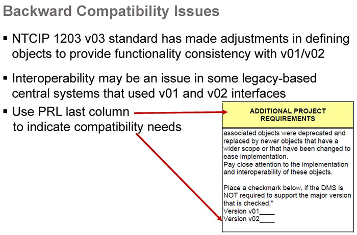
(Extended Text Description: Author's relevant description: v03 has addressed known issues with backward compatibility with v01 and v02. 3.3.7.1 - Backwards Compatibility and Support of Different Versions of NTCIP 1203 In NTCIP 1203 v02, the enhancement of certain functions caused corresponding objects to be replaced. A device conformant with NTCIP 1203 v03 shall by default support functions (and resulting objects) from all existing versions, if said device is required to support that particular functionality. Additional text on the slide follows:
- NTCIP 1203 v03 standard has made adjustments in defining objects to provide functionality consistency with v01/v02
- Interoperability may be an issue in some legacy-based central systems that used v01 and v02 interfaces
- Use PRL last column to indicate compatibility needs
)
Slide 79:
Specifying Requirements Not Covered by the Standard (Extensions)
Support for Extensions
-
The NTCIP standards support extensions
-
For user needs not supported by the standard:
- May result in user-specific requirements
- Specification must include the dialogs and objects to fulfill the user-specific requirements
- Specification May NOT define new dialogs or objects for requirements already supported by the standard
-
For user needs not supported by the standard:
- Benefits: Allows procurers to use the NTCIP family of standards to meet operational needs
Slide 80:
Specifying Requirements Not Covered by the Standard (Extensions)
Drawbacks/Consequences
-
Interoperability may be compromised
- Other management stations that do not support the new objects will be unable to exercise the new capabilities
- If the agency is not consistent on defining how the requirement is fulfilled for all DMSs, interoperability cannot be achieved
- Other agencies with the same requirement must have the same design if sharing control of devices
- Test plans need to be expanded to support the new requirements
- Additional costs
Slide 81:
Specifying Requirements Not Covered by the Standard (Extensions)
Rules for Extensions
- Dialog definitions and particularly object definitions must follow the same configuration as contained in the standard for those dialogs and object definitions contained in it
- Dialogs and object definitions are NOT allowed to be redefined or replaced
- All extended work must be published to other parties affected by the DMS operations
Slide 82:

Slide 83:
Question
Which of the following is a FALSE statement related to a DMS specification?
Answer Choices
- Specification includes PRL-identified user needs
- Project RTM provides project-based design content
- To achieve interoperability either PRL or RTM is required
- Extended standard is not conformant to the DMS standard
Slide 84:
Review of Answers
 a) Specification includes PRL-identified user needs.
Incorrect answer. The statement is true. PRL must be in every DMS specification because it has user needs and requirements.
 b) Project RTM provides project-based design content.
Incorrect answer. The statement is true. RTM is the complete source of DMS design content.
 c) To achieve interoperability either PRL or RTM is required.
Correct! The statement is only False. To ensure interoperability, we need both PRL and RTM and SNMP in specification.
 d) Extended standard is not conformant to the DMS standard.
Incorrect answer. The statement is true. Vendor-specific design will not be conformant to the standard, even with properly done extensions.
Slide 85:
Module Summary
- Briefly Review the Structure of the DMS Standard
- Explain the Purpose of a Requirements Traceability Matrix (RTM) and Its Benefits
- Prepare a Project-Level RTM with Standard-Supplied Requirements and Design Content (Concepts)
- Prepare a DMS Specification (Checklist)
Slide 86:
We Have Now Completed A311a and A311b in the DMS Curriculum
 Module A311a: Understanding User Needs for DMS
Systems based on NTCIP 1203 Standard v03
 Module A311b: Specifying Requirements for DMS
Systems based on NTCIP 1203 Standard v03
 Module T311: Applying Your Test Plan to the NTCIP 1203 v03 DMS Standard
Slide 87:
Next Course Module
Module T311: Applying Your Test Plan to the NTCIP 1203 v03 DMS Standard
Concepts taught in next module (Learning Objectives):
- Describe within the context of a testing lifecycle the role of a test plan and the testing to be undertaken for DMS
- Identify the key elements of NTCIP 1203 v03 relevant to the test plan
- Describe the application of a good test plan to a DMS system being procured
- Describe a process of adapting a test plan based on the selected user needs and requirements
Slide 88:
Thank you for completing this module. Feedback
Please use the Feedback link below to provide us with your thoughts and comments about the value of the training.
Thank you!