Module 15 - A313b
A313b: Specifying Requirements for ESS Systems Based on NTCIP 1204 v04 Standard
HTML of the PowerPoint Presentation
(Note: This document has been converted from a PowerPoint presentation to 508-compliant HTML. The formatting has been adjusted for 508 compliance, but all the original text content is included, plus additional text descriptions for the images, photos and/or diagrams have been provided below.)
Slide 1:

(Extended Text Description: Welcome - Graphic image of introductory slide. A large dark blue rectangle with a wide, light grid pattern at the top half and bands of dark and lighter blue bands below. There is a white square ITS logo box with words "Standards ITS Training - Transit" in green and blue on the middle left side. The word "Welcome" in white is to the right of the logo. Under the logo box is the logo for the U.S. Department of Transpotation, Office of the Assistant Secretary for Research and Technology.)
Slide 2:

(Extended Text Description: This slide, entitled "Welcome" has a photo of Ken Leonard, Director, ITS Joint Program Office, on the left hand side, with his email address, Ken.Leonard@dot.gov. A screen capture snapshot of the home webpage is found on the right hand side - for illustration only - from August 2014. Below this image is a link to the current website: www.its.dot.gov/pcb - this screen capture snapshot shows an example from the Office of the Assistant Secretary for Research and Development - Intelligent Transportation Systems Joint Program Office - ITS Professional Capacity Building Program/Advanced ITS Education. Below the main site banner, it shows the main navigation menu with the following items: About, ITS Training, Knowledge Exchange, Technology Transfer, ITS in Academics, and Media Library. Below the main navigation menu, the page shows various content of the website, including a graphic image of professionals seated in a room during a training program. A text overlay has the text Welcome to ITS Professional Capacity Building. Additional content on the page includes a box entitled What's New and a section labeled Free Training. Again, this image serves for illustration only. The current website link is: https://www.its.dot.gov/pcb.)
Slide 3:
A313b: Specifying Requirements for ESS Systems Based on NTCIP 1204 Standard v04

(Extended Text Description: Author's relevant description: Title slide Module A313b: Identifying Requirements for ESS Systems based on NTCIP 1204 v04 Standard - The slide presents a graphic image under the title that shows a CCTV field photo of a roadway condition on left and on the right side a structure with multiple ESS sensors. In the middle a map of an area is shown. The image together conveys that this module is about ESS sensors installed in roadway environment.)
Slide 4:
Instructor

Raman K. Patel, Ph.D., P.E.
President
RK Patel Associates, Inc.
New York City, NY, USA
Slide 5:
Learning Objectives
- Review the structure of the standard
- Use the PRL and RTM to specify requirements
- Use the RTM to specify the standardized design
- How to specify requirements not covered by the standard
- Infer the relationship between selecting requirements and testing
Slide 6:
Learning Objective 1
- Review the structure of the standard
Slide 7:
Overall Structure of the Environmental Sensors Station (ESS) Standard

(Extended Text Description: Author's relevant description: NTCIP Framework - A graphic of the communication five levels of the NTCIP standards. On the right-side corner, there is a vertical text box that reads NTCIP 1204/NTCIP 1201 which points to Information Level Data Dictionaries and underneath arrow points to SNMP at Application level. This is shown to empathize where these standards are located. The next level is called the Application Level and includes C2C XML, DATEX, FTP, TFTP, SNMP, and STMP. The next level is called the Information Level and includes C2C Messages, Files, Data Objects, and Dynamic Objects. The next higher level is called the Subnetwork Level and includes PPP, Ethernet, and PMPP. The next level is called the Transport Level and includes TCP/IP, UDP/IP, and T2/NULL. These boxes are connected to an overarching box also in the Information Level labeled Functional Area Data Dictionaries with the left-hand side identifying C2C Data Dictionaries and the right-hand side labeled NTCIP Data Dictionaries. The bottom level, last level, is the Plant Level and includes boxes for Dial-up, Fiber, Coax, Wireless, Twisted Pair, and Leased Line.)
Source: NTCIP Guide
Slide 8:
Standard Organization

(Extended Text Description: This slide contains the following text:
Structure of the ESS Standard (NTCIP 1204 v04)
Section 1 -General Section 2 Concept of Operations (Features-User Needs)
Section 3 -Functional Requirements
Section 3.3 -Protocol Requirements List (PRL)
Section 4 - Dialogs (Standardized)
Section 5 - Object Definitions
(Management Information Base - MIB)
Arrows points to Section 2, 3, 4, and 5 from the following text:
Specification writers will need to refer to these sections.)

Slide 9:
Standard Organization
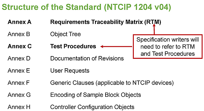
(Extended Text Description: This slide contains the following text:
Standard Organization
Structure of the Standard (NTCIP 1204 v04)
Annex A - Requirements Traceability Matrix (RTM)
Annex B -Object Tree
Annex C - Test Procedures
Annex D - Documentation of Revisions
Annex E - User Requests
Annex F - Generic Clauses (applicable to NTCIP devices)
Annex G - Encoding of Sample Block Objects
Annex H - Controller Configuration Objects
Arrows point to Annex A and C from the following text:
Specification writers will need to refer to RTM and Test Procedures.)

Slide 10:
What Is New in v04
What Has Changed in v04 Compared to v03?
The primary changes from NTCIP 1204 v03 to NTCIP 1204 v04:
- Improved support for multiple sensor readings of the same sensor type
- Improved support for new infrared technologies that collect different sensor readings from a single device
- Expanded support for metadata
This updated Module incorporates new user needs and Test Procedures.

Slide 11:
What Is New in v04
What Has Changed in v04 Compared to v03?
- Reflects lessons learned since publication of NTCIP 1204 v03
- Supports newly identified user needs
- v04 is backward compatible to v03, v02, and v01
- PRL and RTM (some) Headings are renamed in v04
Slide 12:
Requirements Supported by the Standard
What Is a Requirement?
"A statement that identifies a system, product or process' characteristic or constraint, which is unambiguous, clear, unique, consistent, standalone (not grouped), and verifiable, and is deemed necessary for stakeholder acceptability."
- INCOSE Systems Engineering Handbook

Slide 13:
Requirements Supported by the Standard
NTCIP 1204 ESS Standard Definition of a Requirement
"A requirement describes a condition or capability to which a system shall conform; either derived directly from user needs, or stated in a contract, standard, specification, or other normative document.
A desired feature, property, or behavior of a system."
Slide 14:
Requirements Supported by the Standard
Examples of Weather Events
- Close threatened roadways and bridges
- Disseminate information to the public
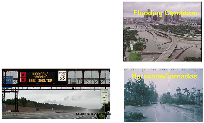
(Extended Text Description: Author's relevant description: Examples of Weather Events - A photo of a Flooding condition of Houston Downtown area is shown on the right top, a photo of Wind condition is shown below that and another photo on left corner shows Hurricane condition warning on a DMS sign.)
Slide 15:
Requirements Supported by the Standard
Best Practice: FDOT High-Wind Alert System
"FOOT has deployed a high-wind alert system for road bridges.
The system assists the transportation and public-safety communities by providing real-time wind speed status information during severe weather events from each monitored bridge structure.
This information is used to assist transportation managers with bridge closure decisions."
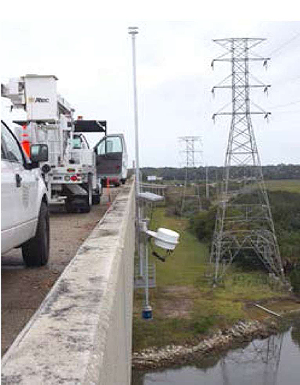
(Extended Text Description: Author's relevant description: Best Practice: FDOT High-Wind Alert System - A photo of a bride structure with ESS mounted on a tower is shown to the right. Photo shows a truck parked on several maintenance vehicles on the bridge next to ESS.)

Slide 16:
Requirements Supported by the Standard
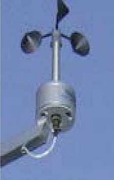
3.5.2.3.2.2 Retrieve Wind Data
Upon request, the ESS shall return the following information for each wind sensor reporting to the ESS:
- the average wind speed recorded during the.............
- the average direction the wind is blowing from.........
- the current wind speed in tenths of meters per second......

Slide 17:
Requirements Supported by the Standard
Retrieve Weather Data
| Observation Date and Time | ||
| 7/3/2015 8:00:02 AM | ||
| Atmospheric Data | ||
| Air Temperature | 61.0°F | |
| Dew Point | 58.6°F | |
| Relative Humidity | 91.0% | |
| Average Wind Speed | 9 rnph(8 knots) | |
| Wind Gust | 10.01 mph(9 knots) | |
| Wind Direction | NE(55°) | |
| Precipitation | None | |
| Visibility | 7.1 Miles | |
| Surface Data | ||
| Location | Surface Temperature | |
| 1-35 NB Driving Deck | 66.7°F | |
| 1-35 NB Driving Pavement | 72.3°F | |
| 1-35 SB Passing Deck | 66.9°F | |
| Sub Surface Data | ||
| Location | Subsurface Temperature | |
| 1-35 NB | 81.1°F | |
| Traffic Data (2-rninute average) | ||
| Location | Speed | Volume |
| 1-35 N/B Drive Lane | 70.8 | 16.0 |
| 1-35 N/B Pass Lane | 73.9 | 5.0 |
| 1-35 S/B Pass Lane | 73.9 | 8.0 |
| 1-35 S/B Drive Lane | 67.7 | 22.0 |
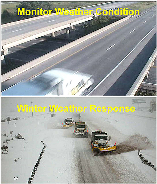
(Extended Text Description: Author's relevant description: Retrieve Weather Data - On the right-side top, a roadway section is shown for Monitor Weather Condition. At bottom, right a photo shows Winter Weather Response with snow removal trucks.)
Slide 18:
Requirements Supported by the Standard
Where to Find ESS Requirements
Categories
Section 3 Functional Requirements [Normative] - 23
3.1 Tutorial [Informative] - 23
3.2 Scope of the Interface [Informative] - 23
3.3 Protocol Requirements List (PRL) - 24
3.3.1 Notation [Informative] - 24
3.3.2 Instructions for Completing the PRL [Informative] - 26
3.3.3 Protocol Requirements List (PRL) Table - 27
3.4 Architecture I Requirements - 46
3.5 Data Exchange and Operational Environment Requirements - 46
3.5.1 ESS Manager Requirements - 46
3 5 2 Sensor Manager Requirements - 4S
3.5.3 PTS Manager Requirements - 69
3.5.4 Backward Compatibility Requirements - 72
3.6 Supplemental Non-Communications Requirements - 75
3.6.1 Required Number of Atmospheric Pressure Sensors - 75
3.6.2 Required Number of Wind Sensors - 75
3.6.3 Required Number of Temperature Sensors - 76
3.6.4 Required Number of Humidity Sensors - 76
Protocol Requirements List (PRL) was discussed in Module A313a - User Needs

Slide 19:
Requirements Supported by the Standard
Where to Find ESS Requirements with Design Elements

(Extended Text Description: This slide contains the following text, with the last row highlighted in red:
Annex A Requirements Traceability Matrix (RTM) [Normative] - 211
A.1 Notation [informative] - 211
A.1.1 Functional Requirement Columns - 211
A.1.2 Dialog Column - 211
A.1.3 Object Columns - 212
A.1.4 Additional Specifications - 212
A.2 Instructions for Completing the RTM [Informative] - 212
A.3 Requirements Traceability Matrix (RTM) Table - 212.)

Slide 20:
Introduce Requirements Traceability Matrix (RTM)
Parts of RTM (Table)
- 2nd line contains the headings of the RTM
FR ID - Section number of the functional requirement, Section 3
| Requirements Traceability Matrix (RTM) | |||||
| FR ID | Functional Requirement | Dialog ID | Object ID |Object Name | Additional Specifications | |
|---|---|---|---|---|---|
| 3.4 | Architectural Requirements | ||||
| 3.5 | Data Exchange and Operational Environment Requirements | ||||
| 3.5.1 | ESS Manager Requirements | ||||
| 3.5.1.1 | ESS Configuration Requirements | ||||
| 3.5.1.1.1 | Retrieve ESS Characteristics | G.1 | |||
| 5.2.1 | essNtcipCategory | ||||
| 5.2.2 | essNtcipSiteDescription | ||||
| 5.3.1 | essTypeofStation | ||||
| 5.4.1 | essLatitude | ||||
| 5.4.2 | essLongitude | ||||
| 5.5.1 | essReferenceHeight | ||||
- Dialog ID - Section number of the dialog associated with this requirement, Appendix G (G1, G2, and G3)
- Object name and location (derived from MIB)
Slide 21:
Introduce Requirements Traceability Matrix (RTM)
Parts of RTM: Example of a Dialog
G.1 Generic SNMP Get Interface
Management station can retrieve data from a Remote Processer Unit (RPU) to fulfill a requirement.
Messages contain a list of objects as defined by the varBindingList structure.
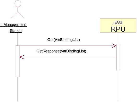
(Extended Text Description: Author's relevant description: An example of a Dialog is shown to the right where a Management station is communicating with a field ESS RPU with a Get message to RPU and a response message from RPU going back to the Management station.)
Slide 22:
Introduce Requirements Traceability Matrix (RTM)
3.5.1.1.1 Retrieve ESS Characteristics Requirement
- Generic dialog G.1 with a set of related objects are allocated by RTM to retrieve ESS data
- User has NO role in selecting dialog/objects

(Extended Text Description: Author's relevant description: This slide contains the following table:
| Requirements Traceability Matrix (RTM) | |||||
| FR ID | Functional Requirement | Dialog ID | Object ID | Object Name | Additional Specifications |
|---|---|---|---|---|---|
| 3.5.1.1.1 | Retrieve ESS Characteristics | G.1 | |||
| 5.2.1 | essNlcipCategory | ||||
| 5.2.2 | essNtcipSiteDescription | ||||
| 5.3.1 | essTypeofStation | ||||
| 5.4.1 | essLatitude | ||||
| 5.4.2 | essLongilude | ||||
| 5.5.1 | essReferenceHeiaht | ||||
On the left side of the table is the following text, overlayed on top:
Fixed Portable Transportable.)

Slide 23:
Introduce Requirements Traceability Matrix (RTM)
Key Benefits of RTM
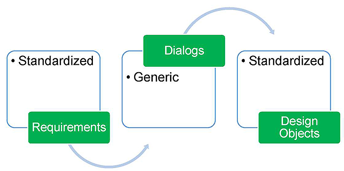
- Maintains order for interoperability, acts as a conformance tool
- Reduces design work (predesigned by the standard)

Source: Patel
Traceability
Creates a common understanding among agencies, developers, vendor, and testers; removes ambiguities.
Slide 24:

Slide 25:
Question
Which of the following is a False statement?
Answer Choices
- ESS requirements are standardized by the standard
- RTM provides benefits to vendors only
- RTM provides standardized design
- NTCIP 1204 v04 is backward compatible to previous versions
Slide 26:
Review of Answers
 a) ESS requirements are standardized by the standard
True statement. All ESS requirements are developed by the standard.
 b) RTM provides benefits to vendors only
False statement. RTM creates a common understanding among all concerned parties: agencies, developers, and vendors.
 c) RTM provides standardized design
True statement. RTM provides a single standardized design for each requirement.
 d) NTCIP 1204 v04 is backward compatible to previous versions.
True statement. v04 is fully compatible to older versions.
Slide 27:
Learning Objectives
- Review the structure of the standard
- Use the PRL and RTM to specify requirements
Slide 28:
Learning Objective 2
- Use the PRL and RTM to specify requirements
Slide 29:
How to Obtain Off-the-Shelf Interoperability?
Terminology
Interoperability: the ability of two or more systems or components to exchange information and use the information that has been exchanged
Off-the-Shelf Interoperability: enabled by the ESS standard and obtained by using well-documented user needs, along with their corresponding requirements and design, that are broadly supported by the industry as a whole

Slide 30:
How to Obtain Off-the-Shelf Interoperability?
What We Must Do to Achieve Interoperability
-
Select same user needs and requirements provided by PRL with:
- Mandatory user needs and associated requirements
- Optional user needs and associated requirements
- Select same standardized dialogs/objects (single design) provided by RTM

Slide 31:
How to Obtain Off-the-Shelf Interoperability?
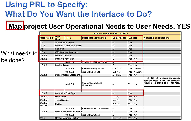
(Extended Text Description: This slide contains the following text and table:
Using PRL to Specify: What Do You Want the Interface to Do?
Map project User Operational Needs to User Needs, YES
The word "Map" in the text above is highlighted in red
What needs to be done?
The rows 2.4 through 2.5.1.2 and 2.5.1.5 are highlighted in red in the table below:
| Protocol Requirements List (PRL) | ||||||
| User Need ID | User Need | FR ID | Functional Requirement | Conformance | Support | Additional Specifications |
|---|---|---|---|---|---|---|
| 2.4 | Architectural Meeds | M | Yes | |||
| 2.4.1 | Generic Architectural Needs | M | Yes | |||
| 2.5 | Fe atures | Yes | ||||
| 2.5.1 | ESS Manaqer Fealures | M | Yes | |||
| 2.5.1.1 | Generic Features | M | Yes | |||
| 2.5.1.2 | Monitor Door Status | O | Yes / No | |||
| 3.5.1.2.1 | Retrieve ESS Door Slatus | M | Yes / NA | |||
| 2.5.1.3 | Monitor Power | O | Yes / No | |||
| 3.5.1.2.2 | Retrieve Battery Stains | 0.1 (1..*) | Yes / No / NA | |||
| 3.5.1.2.3 | Retrieve Line Volts | 0.1 (1..*) | Yes / No / NA | |||
| 2.5.1.4 | Monitor Mobile Station Data | Mobile :M | Yes / NA | |||
| 3.5.1.3.1 | Retrieve Mobile ESS Movement | M | Yes / NA | NTCIP 1204 v04 does not impose any accuracy requirements. Any accuracy requirements should be inserted here. | ||
| 2.5.1.5 | Deteimine ESS Type | M | Yes | |||
|
2.5.1.5.a 2.5.1.5.b 2.5.1 S.c (Mobile) |
Permanent Transportable Mobile |
0.2 (1) 0.2 (1) 0.2 (1) |
Yes / No Yes / No Yes / No |
|||
| 13.5.1.1.1 Retrieve ESS Characteristics | M | Yes | ||||
| 2.5.1.6 | Monitor the Status of the ESS | 0 | Yes / No | |||
| 3.5.1.2.4 | Retrieve ESS Stalus | M | Yes / NA | |||
| 2.5.2 | Sensor Manager Fealures | 0.3 (1...*) | Yes / No | |||
)
Slide 32:
How to Obtain Off-the-Shelf Interoperability?
Using PRL to Specify:
What Do You Want the Interface to Do?
How it is to be done
| Protocol Requirements List (PRL) | ||||||
| User Need ID | User Need | FR ID | Functional Requirement | Conformance | Support | Additional Specifications |
|---|---|---|---|---|---|---|
| 2.4 | Architectural Meeds | M | Yes | |||
| 2.4.1 | Generic Architectural Needs | M | Yes | |||
| 2.5 | Fe atures | Yes | ||||
| 2.5.1 | ESS Manaqer Fealures | M | Yes | |||
| 2.5.1.1 | Generic Features | M | Yes | |||
| 2.5.1.2 | Monitor Door Status | O | Yes / No | |||
| 3.5.1.2.1 | Retrieve ESS Door Slatus | M | Yes / NA | |||
| 2.5.1.3 | Monitor Power | O | Yes / No | |||
| 3.5.1.2.2 | Retrieve Battery Stains | 0.1 (1..*) | Yes / No / NA | |||
| 3.5.1.2.3 | Retrieve Line Volts | 0.1 (1..*) | Yes / No / NA | |||
| 2.5.1.4 | Monitor Mobile Station Data | Mobile :M | Yes / NA | |||
| 3.5.1.3.1 | Retrieve Mobile ESS Movement | M | Yes / NA | NTCIP 1204 v04 does not impose any accuracy requirements. Any accuracy requirements should be inserted here. | ||
| 2.5.1.5 | Deteimine ESS Type | M | Yes | |||
|
2.5.1.5.a 2.5.1.5.b 2.5.1 S.c (Mobile) |
Permanent Transportable Mobile |
0.2 (1) 0.2 (1) 0.2 (1) |
Yes / No Yes / No Yes / No |
|||
| 13.5.1.1.1 Retrieve ESS Characteristics | M | Yes | ||||
| 2.5.1.6 | Monitor the Status of the ESS | 0 | Yes / No | |||
| 3.5.1.2.4 | Retrieve ESS Stalus | M | Yes / NA | |||
| 2.5.2 | Sensor Manager Fealures | 0.3 (1...*) | Yes / No | |||
Slide 33:
Within the PRL, Select a Given Range of Requirements
Select Mandatory User Needs to Conform
Select Optional User Needs if Project Needs Them
Certain User Needs are "Optional," but if selected, all the requirements associated with the User Need become mandatory.
| Protocol Requirements List (PRL) | ||||||
| User Need ID | User Need | FR ID | Functional Requirement | Conformance | Support | Additional Specifications |
|---|---|---|---|---|---|---|
| 2.5.2.1 | Monitor Weather Conditions | 0.4 (1..*) | Yes / No / NA | |||
| 2.5.2.1.1 | Monitor Atmospheric Pressure | 0.5 (1..*) | Yes / No / NA | |||
| 3.5.2.1.10.1 (PressLoc) | Retrieve Atmospheric Pressure Metadata - Location | O | Yes / No / NA | |||
| 3.5.2.1.10.2 | Retrieve Atmospheric Pressure Metadata - Sensor Information | O | Yes / No / NA | |||
| 3.5.2 1.10.3 | Configure Atmospheric Pressure Metadata - Location | PressLoc:0 | Yes / No / NA | |||
| 3.5.2.3.2.10 | Retrieve Atmospheric Pressure | M | Yes / NA | |||
| 3.6.1 | Required Number of Atmospheric Pressure Sensors | M | Yes / NA | The ESS shall support at least ____ (1..255:Default=1) atmospheric pressure sensors. | ||
PRL is NOT a "nice to have" list; unnecessary User Needs will add COST and may even hamper interoperability.
Slide 34:
Within the PRL, Select a Given Range of Requirements
ESS Requirement Categories
3.4 Architectural Requirements
3.5 Data Exchange and Operational Environment Requirements
3 5.1 ESS Manager Requirements
3 5.2 Sensor Manager Requirements
3 5.3 PTS Manager Requirements
3 5.4 Backward Compatibility Requirements
3.6 Supplemental Non-Communications Requirements
3.6.1 Required Number of Atmospheric Pressure Sensors
3 6.2 Required Number of Wind Sensors
3 6.3 Required Number of Temperature Sensors
3 6.4 Required Number of Humidity Sensors
Twenty-four Additional Supplemental Requirements are listed in the standard
Slide 35:
Within the PRL, Select a Given Range of Requirements
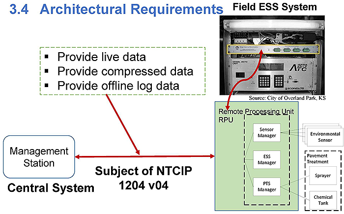
(Extended Text Description: Author's relevant description: Architectural Requirements - A photo at right top shows a field ESS station with a controller, below it RPU block diagram is shown which in-turn interconnects to a Central management station. Text on the left connects with the text Subject of NTCIP 1204 v04 with arrows:
3.4 Architectural Requirements
- Provide live data
- Provide compre.ssed data
- Provide offline log data
Management Station
Central System
Subject of NTCIP 1204 v04.)
Slide 36:
Within the PRL, Select a Given Range of Requirements
3.5 Data Exchange and Operational Environment Requirements for ESS Manager (3.5.1)

(Extended Text Description: This slide contains the following text with arrows running from left to right highlighting text in red:
Configuration points to Location and Retrieving and configuring the ESS characteristics Permanent ESS Transportable ESS Mobile ESS
Monitoring points to Sensor data retrieval requirements
Data retrieval points to Mobile ESS data retrieval Location-Speed-Direction.)
Slide 37:
Within the PRL, Select a Given Range of Requirements
ESS Monitoring Requirement
3.5.1.2.1 Retrieve ESS Door Status
Upon request, the ESS shall return an indication as to whether any doors related to the ESS (e.g., cabinet doors, housing doors, etc.) are open
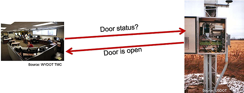
(Extended Text Description: Author's relevant description: ESS Monitoring Requirement - A TMC set up is shown on left bottom is shown communicating with a message to the ESS controller with door which is open. The field controller is at right side.)

Slide 38:
Within the PRL, Select a Given Range of Requirements
3.5 Data Exchange and Operational Environment Requirements for Sensor Manager (3.5.2)

(Extended Text Description: This slide contains the following text with arrows running from left to right highlighting text in red:
Configuration points to Configure sensors, snapshot cameras
Monitoring points to Retrieval of current status of sprayers and the number of sprayer events
Data retrieval points to Sensors metadata.)
Slide 39:
Within the PRL, Select a Given Range of Requirements
3.5 Data Exchange/Operational Environment
Requirements for Pavement Treatment System (PTS) Manager
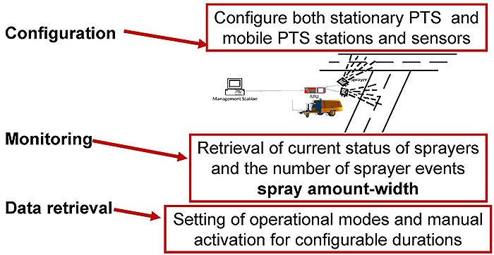
(Extended Text Description: Author's relevant description: This slide contains the same text as the priovious slide, 38, but below the configuration text a diagram of a management station communicating with RPU of a spryer is shown. The ESS is a portable device that can be moved from location to location.)
Slide 40:
Within the PRL, Select a Given Range of Requirements
3.5 Data Exchange and Operational Environment Requirements for Backward Compatibility (3.5.4)
-
Ensure data elements that were deprecated (between version 01, v02, and v03) are compatible within a new or updated deployment
- Example: Wind sensor data was defined differently in v01 versus v02 and v03
- Backward compatibility is secured through PRL Support column
Slide 41:
Within the PRL, Select a Given Range of Requirements
3.6 Supplemental Requirements
3.6.3 Required Number of Temperature Sensors
The ESS shall support the number of temperature sensors as defined by the agency specification. If the agency specification does not define the number of temperature sensors, the number of temperature sensors supported by the ESS is one (1).
| Protocol Requirements List (PRL) | ||||||
| User Need ID | User Need | FR ID | Functional Requirement | Conformance | Support | Additional Specifications |
|---|---|---|---|---|---|---|
| 3.5.2.1.12.2 | Retrieve Temperature Sensor Metadata - Sensor Information | 0 | Yes / No / NA | |||
| 3.5.2.1.12.3 | Configure Temperature Sensor Metadata - Location | Temperature:0; TempLoc:0 | Yes / No / NA | |||
| 3.5.2.3 2.3 | Retrieve Air Temperature | M | Yes / NA | |||
| 3.5.2.3.2.4 | Retrieve Daily Minimum and Maximum Temperature | M | Yes / NA | |||
| 3.5.3 | Required Number of Temperature Sensors | M | Yes / NA | The ESS shall support at least ____ (1..255:Default=1) temperature sensors. | ||
Slide 42:

Slide 43:
Question
Which of the following is a False statement as applied to ESS?
Answer Choices
- Remote Processing Unit (RPU) contains ESS Manager
- Sensor Manager collects data supplied by each sensor
- PRL allows users to select user needs and associated requirements
- Backward compatibility is not addressed by the PRL
Slide 44:
Review of Answers
 a) Remote Processing Unit (RPU) contains ESS Manager
True. RPU houses ESS Manager, Sensor Manager, and PTS Manager.
 b) Sensor Manager collects data supplied by each sensor
True. Sensor Manager manages metadata from all sensors.
 c) PRL allows users to select user needs and associated requirements
True. PRL is the ONLY method to select a USER NEED and associated Requirements.
 d) Backward compatibility is not addressed by the PRL
False. Backward compatibility to v01, v02, and v03 is built into PRL as Optional; user must Select YES for support for this feature as per Section 3.5.4 entries in PRL.
Slide 45:
Learning Objectives
- Review the structure of the standard
- Use the PRL and RTM to specify requirements
- Use the RTM to specify the standardized design
Slide 46:
Learning Objective 3
- Use the RTM to specify the standardized design
Slide 47:
How RTM Fits into the Big Picture, into an ESS Specification
Components of Agency ESS Procurement Specification

(Extended Text Description: This slide contains the following text in three lists/boxes, with the bottom section, Communications Interface Specifications, highlighted in red:
Hardware Specifications
Functional Req.
Performance Req.
Structural Req.
Mechanical Req.
Electrical Req.
Environmental Req.
Software Specifications
Functional Req.
Performance Req.
Communications Interface Specifications
- User Needs
- Functional Req.
- Project PRL, RTM
- Testing Documentation
)
Slide 48:
How RTM Fits into the Big Picture, into an ESS Specification
Maintaining Consistency Among Specification Components
- Communications interface requirements must be consistent with the hardware specification
Example: measuring temperature range
-22°F to+158°F


Slide 49:
How to Properly Trace User Needs to Requirements
Using PRL and RTM in the Specification for Traceability, Conformance, and Interoperability
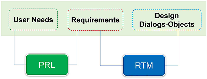

Slide 50:
How to Properly Trace User Needs to Requirements
PRL is the First Step Towards Preparing Communication Interface Specification
- A completed PRL traces the user needs to requirements for the communications interface
- PRL deals only with the information level (ESS application data)
- Underlying communications standards need to be specified too
- Make reference to interface standards
- Be specific to the version and date of issue of a standard

Slide 51:
How to Properly Trace User Needs to Requirements
About ESS Performance Requirements
Performance requirements for the ESS system are not covered by the standards.
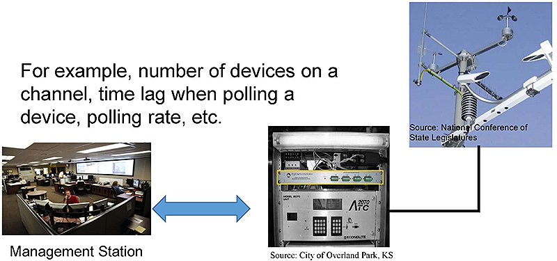
(Extended Text Description: Author's relevant description: About ESS Performance Requirements - At bottom left a TMC is shown communicating to an ESS RPU on left side which in turn is connected to a wind sensor assembly at top right corner. The text above the images is: For example, number of devices on a channel, time lag when polling a device, polling rate, etc..)

Slide 52:
How to Properly Trace User Needs to Requirements
Performance Requirement Supported: Response Time
"The ESS shall process the Get, Get-Next, or Set request in accordance with all of the rules of NTCIP 1103 v02 (assuming that the ESS has permission to transmit) within 100 milliseconds of receiving the last byte of the request."

(Extended Text Description: This slide contains the following table:
| Protocol Requirements List (PRL) | ||||||
| User Need ID | User Need | FR ID | Functional Requirement | Conformance | Support | Additional Specifications |
|---|---|---|---|---|---|---|
| F.2.1.1.2 | Deliver Data | M | Yes | |||
| F.2.1.1.3 | Explore Data | M | Yes | |||
| 3.6.21 | Maximum Response Time far Requests | M | Yes | The Response Time for all requests shall be ___ milliseconds (25-500: Defaults 00). | ||
An arrow from the following text - Note: Users desiring a different response time may indicate this in the PRL - points to the text - The Response Time for all requests shall be ___ milliseconds (25-500: Defaults 00).)

Slide 53:
How to Properly Trace User Needs to Requirements
Handling Additional Requirements in PRL
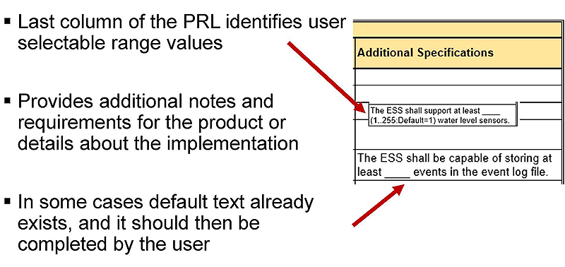
(Extended Text Description: This slide contains the following bulleted items pointing to a table to the right:
- Last column of the PRL identifies user selectable range values
- Provides additional notes and requirements for the product or details about the implementation
- In some cases default text already exists, and it should then be completed by the user
| Additional Specifications |
| The ESS shall support at least ______ (1..255:Default=1) water level sensors. |
| The ESS shall be capable of storing at least _____ events in the event log file. |
The top bullet points to the middle table item. The bottom bullet points to the bottom table item.)

Slide 54:
How to Properly Trace User Needs to Requirements
Environmental Images
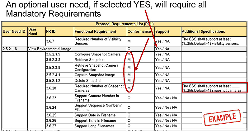
(Extended Text Description: This slide contains the following table:
| Protocol Requirements List (PRL) | ||||||
| User Need ID | User Need | FR ID | Functional Requirement | Conformance | Support | Additional Specifications |
|---|---|---|---|---|---|---|
| 3.6.7 | Required Number of Visibility Sensors | M | Yes / NA | The ESS shall support at least ____ (1.. 255: Default= 1) visibility sensors. | ||
| 2.5.2.1.3 | View Environmental Image | 0 | Yes / No | |||
| 3.5.2.1.9 | Configure Snapshot Camera | M | Yes / NA | |||
| 3.5.2.3.3 | Retrieve Snapshot | M | Yes / NA | |||
| 3.5.2.3.9 | Retrieve Snapshot Camera Configuration | M | Yes / NA | |||
| 3.5.2.4.1 | Capture Snapshot Image | M | Yes / NA | |||
| 3.5.2.4.2 | Delete Snapshot | M | Yes / NA | |||
| 3.6.20 | Required Number of Snapshot Cameras | M | Yes / NA | The ESS shall support at least ____ (1..255:Default=1) snapshot cameras. | ||
| 3.6.23 | Support Camera Number in Filename | 0 | Yes / No / NA | |||
| 3.6.24 | Support Sequence Number in Filename | 0 | Yes / No / NA | |||
| 3.6.25 | Support Date in Filename | 0 | Yes / No / NA | |||
| 3.6.26 | Support Time in Filename | 0 | Yes / No / NA | |||
| 3.6.27 | Support Long Filenames | 0 | Yes / No / NA | |||
The following line of text - An optional user need, if selected YES, will require all Mandatory Requirements - points to the Support column, fourth row. An additional arrow points to the Conformance column, 5th through 10th rows, and a box highlightes the text: The ESS shall support at least ____ (1..255:Default=1) snapshot cameras.)
Slide 55:

Slide 56:
IDAHO DOT Statewide Weather Stations Deployment
Snapshot-Map-Data
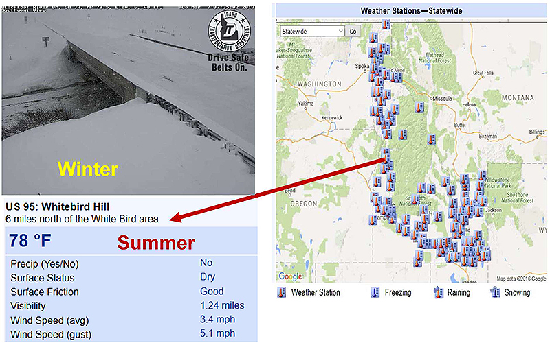
(Extended Text Description: Author's relevant description: Snap-shot Map data - A regional map with ESS locations is shown at right side, with a winter road condition snap-shot to the left side. Key Message: This is a complete example of a weather station built by state agencies in the US, monitoring highway weather CONDITIONS remotely using sensors, camera images, and retrieval process-messages. Such information is placed at a living web page so that it is available to anyone who needs to know of roadway conditions. Sample location weather measurements show US 95: Whitebird Hill - 6 miles north of the White Bird area with the following table data:
| Precip (Yes/No) | No |
| Surface Status | Dry |
| Surface Friction | Good |
| Visibility | 1.24 miles |
| Wind Speed (avg) | 3.4 mph |
| Wind Speed (gust) | 5.1 mph |
)

Slide 57:
Using RTM
Specify Standardized Dialog 4.2.2 to Retrieve Snapshot
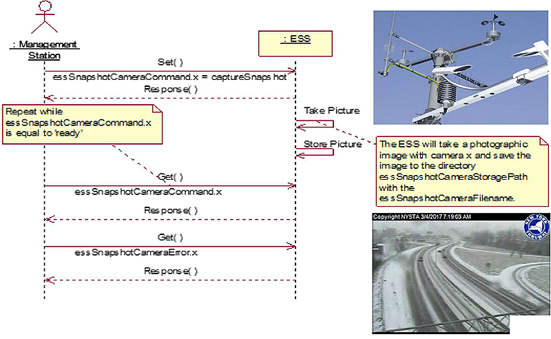
(Extended Text Description: Author's relevant description: Specify Standardized Dialog 4.2.2 to Retrieve Snapshot - A wind sensor assembly is shown at top right corner and a roadway section with winter snow condition is shown at bottom right. Key Message: This example of ESS Dialog enables retrieving a snapshot. The message is what we get done using a dialog, not details. The standardized dialog for a management station to retrieve a snapshot image shall conform to NTCIP 2303:2001.)
Source: NTCIP 1204 v04
Figure 8 Dialog for Capture Snapshot Image

Slide 58:
Using RTM
Using RTM to Specify Design for Retrieving a Snapshot
Standardized dialog 4.2.2 will utilize two objects: 5.17.1 and 5.17.2
| Requirements Traceability Matrix (RTM) | |||||
| FR ID | Functional Requirement | Dialog ID | Object ID | Object Name | Additional Specifications |
|---|---|---|---|---|---|
| 3.5.2.3.8 | Retrieve Snapshot | 4.2.2 |
Upon ESS delivery the FTP username shall be ___________ Upon ESS delivery, the FTP password shall be ___________ Note: For agencies that restrict the use of FTP, see Annex E.3 for additional information. |
||
| 5.17.1 | <not an SNMP Object> Snapshot.filename:text | ||||
| 5.17.2 | <not an SNMP object> Snapshot.image:frame | ||||

Slide 59:
Using RTM
Example
A state highway winter maintenance unit has a user need to procure a sprayer as part of an ESS

(Extended Text Description: Author's relevant description: Example - A snow removal truck fleet is shown in winter condition photo at bottom right side. A sketch of a winter vehicle equipped with salt spreading is shown at left side. Key Message: This and the next slide walk though PRL and RTM entries that support this user need. This user need example was selected as lately more mobile applications are seen in deployments to cope with weather conditions on highways.)
Source: IDDOT

Slide 60:
Using RTM
Example: PRL Entries That Support User Need

(Extended Text Description: This slide contains the following table, with the word Yes highlighted in the Support column on all rows:
| Protocol Requirements List (PRL) | ||||||
| User Need ID | User Need | FR ID | Functional Requirement | Conformance | Support | Additional Specifications |
|---|---|---|---|---|---|---|
| 2.5.3.2 | Manage Mobile Spray System | Mobile: 0 | Yes / No / NA | |||
| 3.5.2.1.21.1 (PTSLoc) | Retrieve Pavement Treatment System Metadata - Location | 0 | Yes / No / NA | |||
| 3.5.2.1.21.2 | Retrieve Pavement Treatment Metadata - System Information | 0 | Yes / No / NA | |||
| 3.5.2.1.21.3 | Configure Pavement Treatment System Metadata - Location | PTSLoc:0 | Yes / No / NA | |||
| 3.5.3 1 4 | Configure Mobile Pavement Treatment System | 0 | Yes / No / NA | |||
| 3.5.3.1.5 | Retrieve Mobile Pavement Treatment Configuration | 0 | Yes / No / NA | |||
| 3.5.3.2.1 | Retrieve Pavement Treatment Status | M | Yes / NA | |||
| 3.5.3.3.1 | Retrieve Pavement Treatment Profile with Mobile Sources | 0 | Yes / No / NA | |||
| 3.5.3.4.1 | Set PTS Operational Mode | 0 | Yes / No / NA | |||
| 3.5.3.4.2 | Manually Activate PTS Sprayer | 0 | Yes / No / NA | |||
)

Slide 61:
Using RTM
RTM Entries That Support Requirements
Using Standard-Supplied Table Dialogs to Retrieve Data and Configure ESS
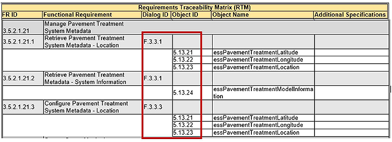
(Extended Text Description: This slide contains the following table, with the Dialog ID and Object ID columns highlighted in red:
| Requirements Traceability Matrix (RTM) | |||||
| FR ID | Functional Requirement | Dialog ID | Object ID | Object Name | Additional Specifications |
|---|---|---|---|---|---|
| 3.5 2 1 21 | Manage Pavement Treatment System Metadata | ||||
| 3.5.2.1.21.1 | Retrieve Pavement Treatment System Metadata - Location | F.3.3.1 | |||
| 5.13.21 | essPavementTreatmentLatitude | ||||
| 5.13.22 | essPavementTreatmentLongitude | ||||
| 5.13.23 | essPavementTreatmentLocation | ||||
| 3.5.2.1.21.2 | Retrieve Pavement Treatment Metadata - System Information | F.3.3.1 | |||
| 5.13 24 | essPavementTreatmentModellnformation | ||||
| 3.5.2.1.21.3 | Configure Pavement Treatment System Metadata - Location | F.3.3.3 | |||
| 5.13.21 | essPavementTreatmentLatitude | ||||
| 5.13.22 | essPavementTreatmentLongitude | ||||
| 5.13.23 | essPavementTreatmentLocation | ||||
)

Slide 62:
Using RTM
Steps to Achieve Conformance to Standard
- Secure user need support by selecting YES in the PRL, making those requirements Mandatory.
- RTM-identified dialogs, in proper sequence-order.
- RTM-identified objects as allocated by the standard.
- Both PRL and RTM are required for Conformance to the standard.
Implementations seeking to achieve interoperability must have selected same user needs-requirements-dialogs-objects.

Slide 63:

Slide 64:
Question
Which of the following is Not a correct statement as applied to communications interface specification?
Answer Choices
- Project PRL lists standardized user needs
- Only PRL is necessary for conformance to standard
- PRL lists optional user needs
- RTM provides complete design
Slide 65:
Review of Answers
 a) Project PRL lists standardized user needs
Correct statement PRL lists ESS standardized user needs.
 b) Only PRL is necessary for conformance to standard
Incorrect statement. Both PRL and RTM are needed to ensure conformance to the standard.
 c) PRL lists optional user needs
Correct statement. PRL lists both optional and mandatory user needs; the specification must indicate support for Optional needs.
 d) RTM provides complete design
Correct statement. RTM provides dialogs and objects in order to complete a message to the ESS device.
Slide 66:
Learning Objectives
- Review the structure of the standard
- Use the PRL and RTM to specify requirements
- Use the RTM to specify the standardized design
- How to specify requirements not covered by the standard
Slide 67:
Learning Objective 4
- How to specify requirements not covered by the standard
Slide 68:
Context and Conditions for Extending the Standard
Context: When Do We Extend the Standard?
Why?
- Current standard (v04) provides for common ESS requirements, including some newly added features
- However, there may be some features and requirements specific to a certain application not yet covered
Example of an Unmet User Need:
An agency may have a need for monitoring an over-height sensor at a tunnel entrance.
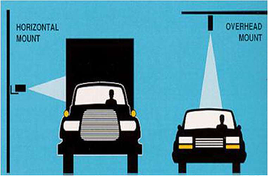
(Extended Text Description: Author's relevant description: Context: When Do We Extend the Standard? Why? A side mounted and a top-mounted Height Measurement sensor is shown in simple diagram at right side.)
Source: FHWA
Slide 69:
Context and Conditions for Extending the Standard
Conditions: What/How to Do It?
- Adding new objects (user needs) to ESS MIB is possible if it is documented and made available to anyone (agency, other vendors, developers)
- Agency must make sure that the vendor-supplied ESS design objects are based on ASN.1 format and the MIB structure
- Agency must specify a dialog and private objects in an approved RTM
Slide 70:
Context and Conditions for Extending the Standard
Technical Conditions
- When a new requirement associates a design object, behavior of the device may be affected
- ASN.1 (Abstract Syntax Notation)-based Objects must support READ operation for retrieval and WRITE operation for control functions without restrictions
- Syntax must be a nonnegative Integer/Bytes
- Object must have an OID (Object ID) within the current MIB node
- Only Simple Network Management Protocol (SNMP) interface will be allowed (as per NTCIP 1103 rules)
Slide 71:
Benefits and Drawbacks
Benefits of an Extension
- Allows procurers to use the NTCIP family of standards and still support operational or user needs not supported by the family
- New operational needs may emerge within a regional or corridor context, or new applications such as Connected Vehicles or Integrated Corridor Management (ICM); some flexibility is useful
Slide 72:
Benefits and Drawbacks
Drawbacks of an Extension
- Other management stations that do not support the new objects will be unable to exercise the new capabilities
- Additional cost of (custom) integration, test procedures, and maintenance
- Vendor's reluctance to share features with other implementations
- Other potential unknown issues (bugs) typically are discovered in the implementation stage
- Private objects impact interoperability/interchangeability adversely and may have further impact on regional RWIS
Slide 73:

Slide 74:
Question
Which of the following is a Correct statement related to ESS extension?
Answer Choices
- Extension will be conformant to the ESS standard
- Extension will break regional RWIS interoperability
- ESS implementation with extensions is manageable
- Extension does not affect remote operation of ESS field devices
Slide 75:
Review of Answers
 a) Extension will be conformant to the ESS standard
Incorrect statement. A testing process is needed to prove that an extended implementation is conformant to the standard.
 b) Extension will break regional RWIS interoperability
Correct statement. Extended design in one implementation will not be known to other deployments or versions; user needs and requirements may not be the same regionally.
 c) ESS implementation with extensions is manageable
Incorrect statement. The additional cost of integration, test procedures, and maintenance will not be in best interest of agency.
 d) Extension does not affect remote operation of ESS field devices
Incorrect statement. Remote operation by management stations are affected by extended implementation, and may result in local operation only.
Slide 76:
Learning Objectives
- Review the structure of the standard
- Use the PRL and RTM to specify requirements
- Use the RTM to specify the standardized design
- How to specify requirements not covered by the standard
- Infer the relationship between selecting requirements and testing
Slide 77:
Learning Objective 5
- Infer the relationship between selecting requirements and testing
Slide 78:
Considerations for Testing
Testing for Validation of User Needs Testing for Verification of Requirements
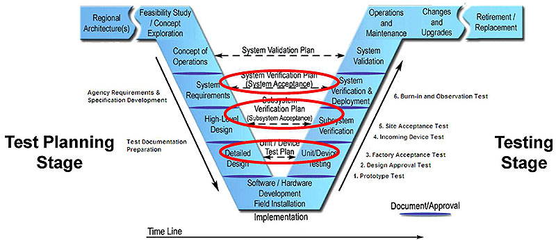
(Extended Text Description: Author's relevant description: Testing for Validation of User Needs - Testing for Verification of Requirements - Vee diagram is used to explain at what stage in life cycle we prepare testing document- Documentation Preparation-specification. A bracket is shown pointing to high level, detailed design stage. On the right leg of the Vee-Communications interface Level Tests to be undertaken is pointing to a red circle that covers stages of testing-beginning with unit/device test. A red curved arrow connects both legs of Vee to indicate role of testing documentation. A Detailed Explanation of V Diagram A graphic of the systems engineering process (SEP) is shown. The main graphic of the SEP is a V-shaped diagram with some additional horizontal "wings" on the left and right side of the top of the V. Starting from the left "wing" the steps are regional architecture, needs assessment, concept selection, project planning, and systems engineering management planning. At this point the steps begin to descend the left side of the V with concept of operations, system requirements, high-level design, detailed design, and software hardware and field installation. At this point the steps begin to ascend the right side of the V with unit device testing, subsystem verification, system verification and deployment, system validation, and operations and maintenance. At this point the steps are on the right "wing" of the V with changes and upgrades and retirement/replacement. The following arrows supplement the figure: 1. A time line at the bottom of the figure indicating that all steps proceed over time with the steps forming the V overlapping one another. 2. A downward arrow on the left side of the V that indicates that these steps deal with decomposition and definition. 3. An upward arrow on the right side of the V that indicates that these steps deal with integration. 4. A horizontal arrow near the bottom of the center of the V that connects the detailed design step to the unit testing step. 5. A horizontal arrow a little higher that connects the subsystem requirements step with the subsystem verification step. 6. A horizontal arrow a little higher that connects the system requirements step with the system verification step. 7. A horizontal arrow near the top of the V that connects the concept of operations step with the system validation step. Finally, major steps are separated by a barrier that is labeled "document approval." This graphical view of SEP life cycle process used to show where SSM user needs/requirements are located. In this slide, at the top of the Vee, there are three boxes in yellow.)
Source: PCB-FHWA
Slide 79:
Considerations for Testing
Relationship Between Selecting Requirements and Testing
- Test procedures are standardized in NTCIP 1204 v04, Annex C
- A separate table, "Requirements to Test Case Traceability Table," traces requirements to test cases (Annex C)
| Requirement | Test Case | ||
| ID | Title | ID | Title |
|---|---|---|---|
| 3.5 | |||
| 3.5.1 | ESS Manager Requirements | ||
| 3.5.1.1 | ESS Configuration Requirements | ||
| 3.5.1.1.1 | Retrieve ESS Characteristics | ||
| C.2.3.1.1 | ESS Characteristics | ||
Module T313: Applying Your Test Plan to the ESS Systems Based on NTCIP 1204 v04 ESS Standard

Slide 80:
Considerations for Testing
Specifications should include Test Procedures (Annex C) to verify requirements selected in PRL
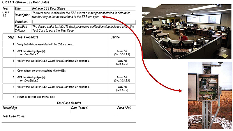
(Extended Text Description: Author's relevant description: Specifications should include Test Procedures (Annex C) to verify requirements selected in PRL - A TMC is communicating to a field controller is shown on the right side. To the left, is the following table:
C.2.3.1.3 Retrieve ESS Door Status
| Test Case: 1.3 | Title: | Retrieve ESS Door Status | |||
| Description: | This test case verifies that the ESS ailows a management station to determine whether any of the doors related to the ESS are open. | ||||
| Variables: | |||||
| Pass/Fail Criteria: | The device under test (OUT) shall pass every verification step included within the Test Case to pass the Test Case. | ||||
| Step | Test Procedure | Device | |||
|---|---|---|---|---|---|
| 1 | Verify that all doors associated with the ESS are closed. | ||||
| 2 | GET the following objects): sessDoorStatus 0 | Pass / Fail (Sec. 3.5.1.2.1) | |||
| 3 | VERI FY lhal the RESPONSE VALUE for essDoorStalus.0 is equal to 0. | Pass / Fail ( Sec. 5.3.2) | |||
| 4 | Open at least one door associated with the ESS | ||||
| 5 | GET the following object(s): >essDoorStatus.0 | Pass / Fail (Sec. 3.5.1.2.1) | |||
| 6 | VERIFY that the RESPONSE VALUE for essDoorStatus.0 is equal to 1. | Pass / Fail (Sec. 5.3.2) | |||
| 7 | Return all doors to their original stale. | ||||
| Test Case Results | |||||
| Tested By: | Date Tested: | Pass/ Fail | |||
| Test Case Notes: | |||||
)

Slide 81:

Slide 82:
Question
Which is Not a correct statement as applied to ESS Testing?
Answer Choices
- Test procedures connect requirements to testing steps
- NTCIP 1204 v04 standard provides test procedures
- Test plan documentation includes test procedures
- Test planning is done at the testing stage
Slide 83:
Review of Answers
 a) Test procedures connect requirements to testing steps
The statement is true. Steps to testing are listed in test procedures.
 b) NTCIP 1204 v04 standard provides test procedures
The statement is true. Test procedures are provided by v04.
 c) Test Plan documentation includes test procedures
The statement is true. The ESS Test Plan does include test procedures.
 d) Test planning is done at the testing stage
False. This statement is incorrect. Test planning occurs at the early stage of user needs/requirements setting, not at a later stage.
Slide 84:
Module Summary
- Review the structure of the standard
- Use the PRL and RTM to specify requirements
- Use the RTM to specify the standardized design
- How to specify requirements not covered by the standard
- Infer the relationship between selecting requirements and testing
Slide 85:
We Have Now Completed A313a and A313b in the ESS Curriculum
 Module A313a:
Understanding User Needs for ESS Systems Based on NTCIP 1204 v04 ESS Standard
 Module A313b:
Specifying Requirements for ESS Systems Based on NTCIP 1204 v04 ESS Standard
 Module T313:
Applying Your Test Plan to the ESS Systems Based on NTCIP 1204 v04 ESS Standard
Slide 86:
Next Course Module
Module T313: Applying Your Test Plan to the ESS Systems Bon NTCIP 1204 v04 ESS Standard
Concepts taught in next module (Learning Objectives):
- Describe within the context of the testing lifecycle the role of test plans and the testing to be undertaken
- Identify key elements of NTCIP 1204 v04 relevant to the test plan
- Describe the application of a good test plan to an ESS system being procured
- Describe the testing of an ESS using standard procedures
Slide 87:
Thank you for completing this module.
Feedback
Please use the Feedback link below to provide us with your thoughts and comments about the value of the training.
Thank you!