Module 16 - A321b
A321b: Specifying Requirements for Traffic Management Systems Based on TMDD v3.0 Standard
HTML of the PowerPoint Presentation
(Note: This document has been converted from a PowerPoint presentation to 508-compliant HTML. The formatting has been adjusted for 508 compliance, but all the original text content is included, plus additional text descriptions for the images, photos and/or diagrams have been provided below.)
Slide 1:

(Extended Text Description: Slide 1: Welcome - Graphic image of introductory slide. A large dark blue rectangle with a wide, light grid pattern at the top half and bands of dark and lighter blue bands below. There is a white square ITS logo box with words “Standards ITS Training” in green and blue on the middle left side. The word “Welcome” in white is to the right of the logo. Under the logo box are the words “RITA Intelligent Transportation Systems Joint Program Office.”)
Slide 2:
Welcome

Shelley Row, P.E., PTOE
Director
ITS Joint Program Office

(Extended Text Description: Slide 2: Screen capture snapshot of RITA website - for illustration only. Below this image is a link to the current website: https://www.its.dot.gov/pcb - this screen capture snapshot shows an example from the RITA website from June 3, 2011. At the top of the page it shows the RITA logo with the text Research and Innovative Technology Administration - Intelligent Transportation Systems. Below the main site banner, it shows the main navigation menu with the following items: About RITA, Communities of Interest, Contact Us, Press Room, RITA Offices, Site Map, and a Search button. Below the main navigation menu, it shows a sub-navigation menu with the following items: About Us, T3 Webinars, ITS Peer-to-Peer, Resources, Local ITS PCB and Testimonials. Beneath the sub-navigation menu, the page is sub-titled "ITS Professional Capacity Building Program" and is divided into sub-sections such as "Welcome to ITS Professional Building", "News", "ITS Technical Assistance" and "Scheduled T3 Webinars". Again, this image serves for illustration only. The current website link is: https://www.its.dot.gov/pcb)
(Note: There is additional text attached to this slide that includes the following introductory information from Shelley Row):
"ITS Standards can make your life easier. Your procurements will go more smoothly and you’ll encourage competition, but only if you know how to write them into your specifications and test them. This module is one in a series that covers practical applications for acquiring and testing standards-based ITS systems.
I am Shelley Row the director of the ITS Joint Program Office for USDOT and I want to welcome you to our newly redesigned ITS standards training program of which this module is a part. We are pleased to be working with our partner, the Institute of Transportation Engineers, to deliver this new approach to training that combines web based modules with instructor interaction to bring the latest in ITS learning to busy professionals like you.
This combined approach allows interested professionals to schedule training at your convenience, without the need to travel. After you complete this training, we hope that you will tell colleagues and customers about the latest ITS standards and encourage them to take advantage of the archived version of the webinars.
ITS Standards training is one of the first offerings of our updated Professional Capacity Training Program. Through the PCB program we prepare professionals to adopt proven and emerging ITS technologies that will make surface transportation safer, smarter and greener which improves livability for us all. You can find information on additional modules and training programs on our web site ITS PCB Home.
Please help us make even more improvements to our training modules through the evaluation process. We look forward to hearing your comments. Thank you for participating and we hope you find this module helpful."
Slide 3:
A321b
Specifying Requirements for Traffic Management Systems Based on TMDD v3.0 Standard
Slide 4:
Target Audience
- Engineering and planning staff
- Emergency management and public safety
- Traffic management center (TMC) and operations staff
- System developers
- Public and private sectors
- Coders
Slide 5:
Instructor

Raman K. Patel, Ph.D., P.E.
President
RK Patel Associates, Inc. New York, NY, USA
Slide 6:
Curriculum Path (SEP)

(Extended Text Description: A graphical illustration indicating the sequence of training modules for the standards that include Systems Engineering Process content. Each module is represented by a box with the name of the module in it and an arrow showing the logical flow of the modules and the current module highlighted. The first box is labeled “I101 Using ITS Standards: An Overview.” An arrow from this box connects it to a highlighted box labeled “A101 Introduction to Acquiring Standards-based ITS Systems,” representing this module. An arrow from this box connects it to a box labeled “A102 Introduction to User Needs Identification.” An arrow from this box connects it to a box located at the start of the next line labeled “A201 Details on Acquiring Standards-based ITS Systems.” An arrow from this box connects it to a box labeled “A3xxa Understanding User Needs for NTCIP 12xx vxx.” Finally, an arrow from this box connects it to a box labeled “A3xxb Specifying Requirements for NTCIP 12xx vxx.”)
Slide 7:
Curriculum Path (Non-SEP)
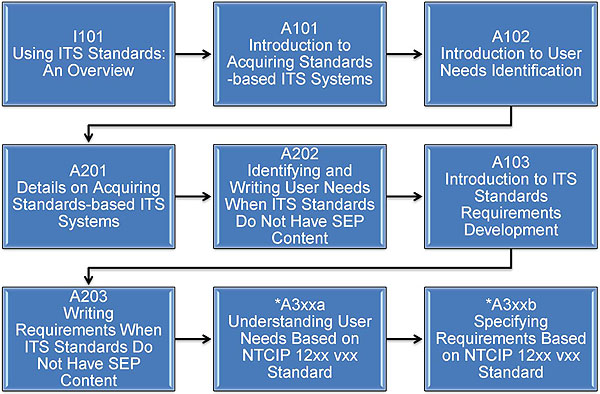
(Extended Text Description:A graphical illustration indicating the sequence of training modules for the standards that do not include Systems Engineering Process content. Each module is represented by a box with the name of the module in it and an arrow showing the logical flow of the modules and the current module highlighted. The first box is labeled “I101 Using ITS Standards: An Overview.” An arrow from this box connects it to a highlighted box labeled “A101 Introduction to Acquiring Standards-based ITS Systems,” representing this module. An arrow from this box connects it to a box labeled “A102 Introduction to User Needs Identification.” An arrow from this box connects it to a box located at the start of the next line labeled “A201 Details on Acquiring Standards-based ITS Systems.” An arrow from this box connects it to a box located at the start of the next line labeled “A203 Writing Standards-based ITS System Requirements.” An arrow from this box connects it to a box labeled “A3xxa Understanding User Needs Based on NTCIP 12xx vxx.” Finally, an arrow from this box connects it to a box labeled “A3xxb Specifying Requirements Based on NTCIP 12xx vxx.” The last two boxes contain an asterisk indicating that they are expected to be included in the Year 2 training modules.)
Slide 8:
Recommended Prerequisites
- I101 Using ITS Standards: An Overview
- A101 Introduction to Acquiring Standards-based ITS Systems
- A102 Introduction to User Needs Identification
- A201 Details on Acquiring Standards-based ITS Systems
- A321a Understanding User Needs for Traffic Management Systems Based on TMDD v3.0 Standard
Slide 9:
Recommended Prerequisites (cont.)
Basic knowledge of the following areas is helpful:
- Intelligent Transportation Systems (ITS)
- Managing ITS deployment projects
- Government procurement processes
- Benefits of standards
- Systems Engineering Process (SEP)
- Traffic Management Centers (TMCs)
Slide 10:
Learning Objectives
1. Discuss continuity with the TMDD user needs module Module A321a:
- Structure of the standard
- Role of NRTM
2. Understanding requirements
3. How to use Requirements Traceability Matrix (RTM) to specify standardized design concepts
Slide 11:
Learning Objectives (cont.)
4. Discuss the use of requirements from the NRTM and RTM in the specification
5. How to extend TMDD v3.0 standard
6. Introduce the TMDD v3.0 Guide as a resource
Slide 12:
Learning Objective #1
Review of Module A321a
Key Areas
- TMDD v3.0 standard supports system interface development for Center-to-Center Communications.
- Structure provides definitions of user needs, requirements, and data concepts for specification.
- Covers operational needs in 8 categories.
- Teaches how to develop Needs to Requirements Traceability Matrix (NRTM) for a project.
Slide 13:
Learning Objective #1
What is a System Interface?
"a system interface is a shared boundary across which information is passed"

(Extended Text Description: What is a System Interface? This slide has a large square blue background box. On the left side inside this box a circle with text center system appears, next to circle which a vertical rectangular box with text "system interface" appears. This conveys that both share a boundary. Into and out of system interface box, one set of separate arrows that shows message in and message out connects to outside world. Another set appears bellow to show that more than one messages flow in and out of system interface that makes boundary with the center system. Finally, a broken square border appears over system interface and messages in-out to show that together they make a boundary with the center system to provide capability of messaging. The entire graphic conveys system interface definition.)
Slide 14:
Learning Objective #1
System Interface (SI) Implementation
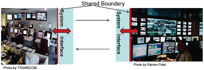
(Extended Text Description: How a System Interface is Implemented? This slide provides real world photos of two TMCs: one on left is a photo of TRASCOM center and one on right is NYC Joint TMC. Both centers are shown with system interface on side of photos and two separate arrows flow between these TMC to show that they have a common system interfaces that communicate information to each other. This information exchange then is used to manage assets and other entities, manage information, monitor status and control devices. The slide graphics have made a point that these real-world center operations use common system interface to carry out operations in real-time and improve their efficiency.)
SI Uses:
- Manage assets and other entities
- Manage information
- Monitor status
- Control devices
Slide 15:
Learning Objective #1
System Interface Components
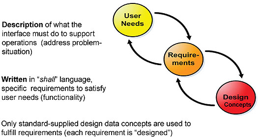
(Extended Text Description:A graphical illustration introduces three circles marked with user needs, requirements and design. The first circle marked as user needs has a curved arrow coming from the second circle marked requirements, and arrow going out to requirements. This depicts that both user needs and requirements are related to each other. Similarly design is connected with requirements with two arrows. Near each circle, text description appears for user needs, requirements and design. Thus, with text and circles we stress that three components make up a specification. Incidentally three Circles have different color shades to show that they are distinct components. The text blurb "Description of what the interface must do to support operations (address problem-situation) appears on the left next to the User Needs circle. The text blurb "Written in "shall" language, specific requirements to satisfy user needs (functionality) is under the first blurb. A final text blurb "Only standard-supplied design data concepts are used to fulfill requirements (each requirement is "designed").)
Slide 16:
Learning Objective #1
User Needs and Requirements Supported
- Connection Management
- Support Authentication and Restrictions
- Provide Information on Organization
- Event Information Sharing
- Provide Roadway Network
- Provide Devices Inventory, Status, and Control
- Share Data for Archiving
- Accept Null Values
Defined in TMDD v3 Volume I
Slide 17:
Learning Objective #1
TMDD v3.0 Standardized Definitions
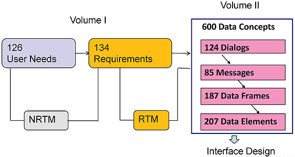
(Extended Text Description: Standardized Definitions: There are three boxes in this slide. Boxes reads inventory of definitions supplied by the TMDD v3 standard: "126 User Needs" in first light blue box with a lower small light blue box linked with a line "NRTM" to "134 Requirements" in second yellow box with lower yellow box "RTM" linked with a line to the last box (Volume I). Last box (Volume II) has "600 Data Concepts", further broken down in a vertical series of purple boxes as "124 dialogs," "85 messages," "187 data frames" and "207 data elements." An arrow flows from data concepts box to text that reads, system "Interface Design.")
Slide 18:
Learning Objective #1
Preparing NRTM for the Project
Select User Needs from Section 2, Volume I based on the project's operational needs
Example: Need to verify DMS status control
|
UN ID |
User Need |
UN Selected |
Req. ID |
Req. |
Conformance |
Support |
Other Req. |
|---|---|---|---|---|---|---|---|
|
2.3.6.4.5 |
YES |
3.3.6.1.4.2 |
Mandatory |
YES |
Contents of Device Control Request Response
Allocate requirements as per the NRTM on page 174, Volume I
Slide 19:
Learning Objective #1
Achieving "Off-the-Shelf" Interoperability
Emphasis
-
Specification shall only use:
- Design solution specified in the standard for each user need and their allocated requirements
- Proprietary solutions are not allowed
Slide 20:
Summary of Learning Objective #1
- TMDD v3.0 standard supports development of a system interface for operational needs
- Centers implement system interface to achieve interoperability

(Extended Text Description: Summary of LO#1: Below the two bullets a graphic with two buildings is shown with arrow from each going to other. This shows that the two centers are communicating to each other and to reinforce that a text box on top of arrows is placed. The text reads as: Center to Center (C2C) Communications.)
Slide 21:
Summary of LO #1 (cont.)
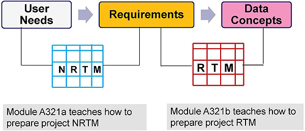
(Extended Text Description: Summary of LO#1 (cont.): The slide conveys that Module A321a teaches how to prepare NRTM and Module A321b teaches how to prepare project RTM. To illustrate this graphical layout is shown with three boxes on first level; First Box reads user needs, second reads requirements and third reads data concepts. Second level shown few spaces below has two boxes: NRTM and other RTM separated by spaces. A solid line from input side of NRTM connects to User Needs box above and a solid line connects output side of NRTM to line Requirements box. NRTM thus depicts relationship between requirements and user needs. It shows that requirements exist because of user needs. A second relationship is shown same way between Requirements and design concepts thru RTM box. This means that RTM connect every requirement to data concepts to be used for that requirement. So, this slide solidly depicts that: NRTM is a relationship between user needs and requirements and RTM is a relationship between requirements and design concepts.)
Slide 22:
Learning Objective #2
Life Cycle Process
Where do Requirements/Data Concepts fit?

(Extended Text Description: Life Cycle Process - A graphic of the systems engineering process (SEP) is shown. The main graphic of the SEP is a V-shaped diagram with some additional horizontal “wings” on the left and right side of the top of the V. Starting from the left “wing” the steps are regional architecture, needs assessment, concept selection, project planning, and systems engineering management planning. At this point the steps begin to descend the left side of the V with concept of operations, system requirements, high-level design, detailed design, and software hardware and field installation. At this point the steps begin to ascend the right side of the V with unit device testing, subsystem verification, system verification and deployment, system validation, and operations and maintenance. At this point the steps are on the right “wing” of the V with changes and upgrades and retirement/replacement. The following arrows supplement the figure: 1) A time line at the bottom of the figure indicating that all steps proceed over time with the steps forming the V overlapping one another. 2) A downward arrow on the left side of the V that indicates that these steps deal with decomposition and definition. 3) An upward arrow on the right side of the V that indicates that these steps deal with integration and recomposition. 4) A horizontal arrow near the bottom of the center of the V that connects the detailed design step to the unit testing step. 5) A horizontal arrow a little higher that connects the subsystem requirements step with the subsystem verification step. 6) A horizontal arrow a little higher that connects the system requirements step with the system verification step. 7) A horizontal arrow near the top of the V that connects the concept of operations step with the system validation step. Finally, major steps are separated by a barrier that is labeled “document approval.” The main point of this slide is to show where requirements and data concepts fit on Vee diagram. To achieve that objective, the graphic shows Requirements pointing with an arrow to System Requirements stage on the Vee diagram and Data Concepts points to detailed design stage of the Vee diagram.)
Slide 23:
Learning Objective #2
Understanding Requirements
-
To satisfy some aspects of a user need, a requirement describes in detail:
- What information is and how it is exchanged with an external center
- What functionality is supported across the system interface
Slide 24:
Learning Objective #2
Example: Structure of a Requirement
Req. ID 3.3.6.1.5.1 (Volume I)
Req. Title Send DMS Control Response Upon Request
Description An owner center shall respond to an authorized external center requesting remote control of a DMS via a one-time control request with a message containing the status of the request.
Slide 25:
Learning Objective #2
Classification of Requirements
-
Mandatory (M): standard requirement for conformance:
- e.g. 3.3.6.1.5.1 Send DMS Control Response Upon Request
- Optional (O): user requirement for compliance
Both must be included in the project specification
Slide 26:
Learning Objective #2
Example: How Requirements are Allocated
10 requirements are allocated to one user need
|
UN ID |
User Need |
UN Selected |
Req. ID |
Require -ment |
Conformance |
Support |
Other Req. |
|---|---|---|---|---|---|---|---|
|
2.3.6.4.5 |
Need to Verify DMS Control Status |
YES |
3.3.6.1.4.2 |
Yes |
|||
|
3.3.6.1.4.2.1 |
Yes |
||||||
|
3.3.6.1.4.2.2.1 |
Yes |
||||||
|
3.3.6.1.4.2.2.2 |
Yes |
||||||
|
3.3.6.1.4.2.2.3 |
Yes |
||||||
|
3.3.6.1.4.2.2.4 |
Yes |
||||||
|
3.3.6.1.5.1 |
Yes |
||||||
|
3.3.6.1.5.2 |
Yes |
||||||
|
3.3.6.1.5.3 |
Yes |
||||||
|
3.3.6.5.4 |
Yes |
Note: Project NRTM references Support column with YES
Slide 27:
Learning Objective #2
Example (cont.)
Requirements shown in column 5
3.3.6.1.4.2 Contents of Device Control Request Response (M)
An owner center shall send a device control request response to an external center.
3.3.6.1.4.2.1 Required Device Control Response Content (M)
3.3.6.1.4.2.2.1 Operator Identifier
(O)
3.3.6.1.4.2.2.2 Operator Lock Identifier
(O)
3.3.6.1.4.2.2.3 Owner Center Organization
(O)
3.3.6.1.4.2.2.4 Operator Last Revised Date and Time
(O)
3.3.6.1.5.1 Send Device Control Status Upon Request
(M)
3.3.6.1.5.2 Contents of the Device Control Status Request
(M)
3.3.6.1.5.3 Contents of Device Control Status Response
(M)
3.3.6.5.4 Request DMS Control Status (M)
Slide 28:
Learning Objective #2
How is a Requirement Implemented?
Each requirements is fulfilled with a single design using data concepts from the RTM
- Standard provides a separate data concept for each requirement
- Project uses only data concept linked to the selected requirement
Slide 29:
Learning Objective #2
Understanding Data Concepts (DCs)
Types of Data Concepts
1. Dialogs
- sequence of message exchanges
2. Messages
- information content being exchanged
3. Data Frames
- grouping of data elements
4. Data Elements
- basic units of data
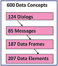
(Extended Text Description: Understanding Data Concepts: The slide lists four data concepts on the left. On the right side a graphical box is shown. The box is labeled as 600 Data Concepts. A breakdown of these 600 DCs is represented with four small text boxes separated by arrows pointing to the next text box. The first text box is 124 dialogs, which is followed by 87 Messages box, which then points to a third text box called 187 Data Frames. This is followed by arrow pointing to the last box called 207 Data Elements.)
Slide 30:

Slide 31:
Learning Objective #2
What determines requirements for a system interface project?
Type your response in the chat room
Slide 32:
Learning Objective #2
Discuss
Do we select all 134 requirements? No
Do we select only mandatory ones? No
Do we select based on the project's needs? Yes
Slide 33:
Learning Objective #2
Example: Share Control of Devices
2.3.6.2 Need to Verify a DMS Control Status
Req. ID
|
3.3.6.1.4.2 |
Contents of Device Control Request Response |
M |
|
3.3.6.1.4.2.1 |
Required Device Control Response Content |
M |
|
3.3.6.1.4.2.2.1 |
Operator Identifier |
O |
|
3.3.6.1.4.2.2.2 |
Operator Lock Identifier |
O |
|
3.3.6.1.4.2.2.3 |
Owner Center Organization |
O |
|
3.3.6.1.4.2.2.4 |
Operator Last Revised Date and Time |
O |
|
3.3.6.1.5.1 |
Send Device Control Status Upon Request |
M |
|
3.3.6.1.5.2 |
Contents of the Device Control Status Request |
M |
|
3.3.6.1.5.3 |
Contents of Device Control Status Response |
M |
|
3.3.6.5.4 |
Request DMS Control Status |
M |
M-Mandatory O-Optional
Slide 34:
Summary of Learning Objective #2
- Detailed requirements are listed in Section 3 of Volume I
- Mandatory requirements must be selected YES
- Each requirement is fulfilled with a single design using DCs in RTM
Slide 35:
Learning Objective #3
Requirements Traceability Matrix (RTM)
- Each requirement is traced to a single data concept type with Requirement ID
- RTM reduces design work
- Helps to achieve interoperability
Volume I Volume II
Section 3 Section 3
|
Requirement ID |
Requirement Title |
Dialog |
Data Concept Name |
DC Type |
Standard Clause |
|---|---|---|---|---|---|
Slide 36:
Learning Objective #3
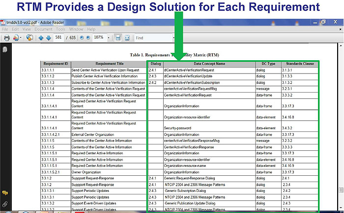
(Extended Text Description: Relevant description as provided by author: RTM Provides a Design Solution for Each Requirement: The RTM view captured from the actual standard is shown with six columns and filled-in rows with requirements and their associated data concepts. A green border is placed over last four columns that relate to DCs and an arrow from the title of the slide points to the border. This means that design solution resides inside this green border portion.)
Slide 37:
Learning Objective #3
Data Concepts Representation
Data Encoding Formats
- Abstract Syntax Notation 1 (ASN.1) Based on ISO 14817
- XML (extensive Markup Language) Based on SAE J2630 Schema
Note:
- Only one format is used in the project RTM
- For interoperability the same format must be used
Slide 38:
Learning Objective #3
Example
Data Element in ASN.1 Representation
DEFINITION: Current volume for the link expressed in vehicles per hour.
link-volume ITS-DATA-ELEMENT ::= { DESCRIPTIVE-NAME "Link.Link-volume:rt" ASN-NAME "Link-volume"
ASN-OBJECT-IDENTIFIER { tmddDataElements 181 }
DEFINITION "Current volume for the link expressed in vehicles per hour."
DESCRIPTIVE-NAME-CONTEXT {"Manage Traffic"}
DATA-CONCEPT-TYPE data-element STANDARD "TMDD"
DATA-TYPE " Link-volume ::= INTEGER (1..100000)
ii
FORMAT "ASN.1 encoding"
UNIT-OF-MEASURE "vehicles per hour" VALID-VALUE-RULE "see the ASN.1 DATA-TYPE"
}
"
}
Slide 39:
Learning Objective #3
Example
Data Element in XML Representation
DEFINITION: Current volume for the link expressed in vehicles per hour.
<xs:simpleType name="Link-volume">
<xs:restriction base="xs:unsignedInt">
<xs:minInclusive value="1"/>
<xs:maxInclusive value="100000"/>
</xs:restriction>
</xs:simpleType>
Slide 40:
Learning Objective #3
Forward/Backward Traceability with RTM

(Extended Text Description: Forward/Backward Traceability with RTM: Graphic shown in this slide is same as one in slide #17, except statistics are not shown and data concepts box conveys relationship among DCs with small arrows from dialogs to messages and from messages to data frames and from data frames to data elements. A backward arrow from RTM box points to Requirements on left and a forward arrow points to DC box on the right. This arrangement conveys that every requirement is traced in both directions during development process.)
Slide 41:
Beneficiaries of RTM
The specification writer
- Using RTM, details in the project specification what data concepts are to be implemented
The user
- Uses RTM as a checklist for the desired interoperability with others
The system integrator
- Uses RTM as a checklist to reduce risk of failure to conform to the standard and comply with the specification
The supplier
- Through RTM, gains details on the data concepts to be included in the implementation
Slide 42:

Slide 43:
Learning Objective #3
What Are the Key Functions of a Project RTM?
Type your response in the chat room
Slide 44:
Learning Objective #3
Summarize RTM Functions
- Project RTM ties the requirements to data concepts and provides a reference to verify that all requirements are contained in the System Interface specification .
Slide 45:
Learning Objective #3
Summarize Conditions for Interoperability
Type your response in the chat room
Slide 46:
Learning Objective #3
Summary of
Conditions for C2C Interoperability
- Use project NRTM to choose the same set of user needs and associated requirements.
- Use project RTM to use the standardized design concepts (solutions).
- Use a common communication protocol .
Concerned centers must adhere to these conditions.
Slide 47:
Learning Objective #4
From Requirements to Data Concepts Using RTM

(Extended Text Description: Relevant information as provided by author: From Requirements to Data Concepts Using RTM: The Vee diagram shown on this slide is same as one in Slide 22 Life Cycle Process. Two steps are shown in text form, one requirements that points to system requirements on Vee and data concepts, a second step text points to high level and detailed design stages. Both slides, 21 and this 44, convey the same meaning.)
Slide 48:
Learning Objective #4
Data Concepts Organization: Dialog-Message-Data Frame-Data Element
Example of CCTV Requirements Traced to DCs
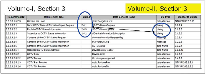
(Extended Text Description: Relevant information as provided by author: Data concepts Organization: Dialogs, Messages, Data Frames and Data Elements: The RTM table graphic is shown with six columns and 12 rows for requirements and their associated DCs. The columns from left to right are: Requirement ID, Requirement Title, Dialog, Data Concept Name, DC Type and Standard Clause. Dialog Column shows an oval over entry 2.4.1, 2.4.2 and 2.4.3 beginning with row 2, 3 and 4. These dialogs are generic and serve requirements. A small circle is placed in DC Type column to highlight that they (2.4.1 to 2.4.3) are dialogs.)
Slide 49:
Learning Objective #4
Generic Dialogs
Dialogs Describe a Sequence of Messages

(Extended Text Description: Generic Dialogs: A graphic of two buildings shown here is same as one in slide 19. The word dialog is shown over the arrow. Three dialogs are listed below the graphic.)
-
Types Dialogs:
- 2.4.1 Request-Response Dialog
- 2.4.2 Subscription Dialog
- 2.4.3 Publication Dialog
Slide 50:
Learning Objective #4
Generic Dialog 2.4.1 Request-Response
- EC initiates the request to send information or a control message
- OC responds with a message
- Upon error OC returns an error message
M-Mandatory
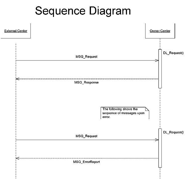
(Extended Text Description: Relevant information as provided by author: Generic Request-Response Dialog 2.4.1: Request-Response dialog sequence diagram is shown to the right of a text that describes what this generic dialog means. The graphic shows External Center on left and Owning Center on the right and a vertical rectangular is shown under OC in which all arrows end or originate. There are light vertical lines under each center top to down. A request message with an arrow from EC to OC is shown and another arrow from OC to EC is shown for response message. Similarly a set of arrows are shown further bellow for error, where a owner center returns an error messages to EC.)
Slide 51:
Learning Objective #4
Generic Dialog 2.4.2
Subscription
- EC initiates the subscription message
- Message is accepted by the OC
- Mandatory for generation of information updates receipt.
- Upon error, the OC shall return an error message.
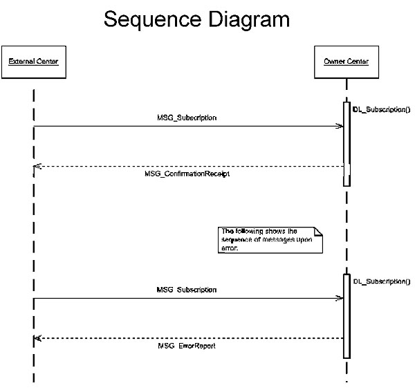
(Extended Text Description: Relevant information as provided by author: Generic Request-Response Dialog 2.4.2: Same as above slide #50, except it explains subscription generic dialog.)
Slide 52:
Learning Objective #4
Generic Dialog 2.4.3
- Upon acceptance of a subscription dialog, an OC shall provide information updates to an EC
- Upon error, the OC shall return an error message.
(publication message is same as a response)
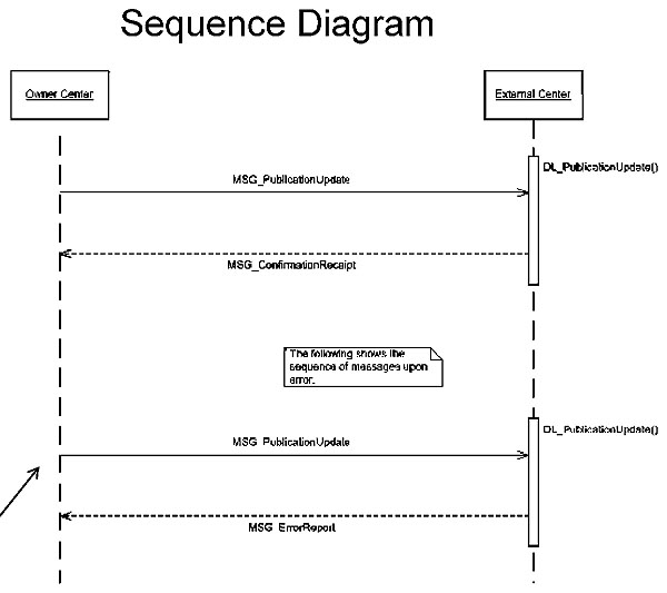
(Extended Text Description: Relevant information as provided by author: Same as above slide#51, except it explains publication generic dialog.)
Slide 53:
Learning Objective #4
Illustration of 2.4.1 Dialog
Display a New Message on a DMS
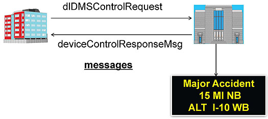
(Extended Text Description: Illustration: EC is requesting to display a new message on a remote DMS: Same graphic shown in slide 20 is shown here with a text dlDMSControlRequest over the arrows. A separate arrow from the Owning Center on right points to a DMS sign below that displays a three line message: Major Accident, 15 MI NB, ALT I-10 WB. The intent is show how an EC can request to display a message on remote DMS.)
Slide 54:
Learning Objective #4
Example of a Partially Populated RTM
Display a Message on a Remote DMS
dlDMSControlRequest
|
Requirement ID |
Requirement Title |
Dialog |
Data Concept Name |
Data Concept Type |
Standard Clause |
|---|---|---|---|---|---|
|
3.3.6.1.4.1 |
Contents of Device Control Request Header |
DeviceControlRequestHeader |
data-frame |
3.3.5.2 |
|
|
3.3.6.1.4.1.1 |
Required Device Control Request Header Content |
Organizationlnformation |
data-frame |
3.3.17.3 |
|
|
3.3.6.5.3.1 |
Send DMS Control Response Upon Request |
2.4.1 |
dlDMSControlRequest |
dialog |
3.1.6.1 |
|
3.3.6.5.3.2 |
Contents of DMS Control Request |
dMSControlRequestMsg |
message |
3.2.6.1 |
|
|
3.3.6.5.3.2.1 |
Required DMS Control Request Content |
DeviceControlRequestHeader |
data-frame |
3.3.5.2 |
|
|
3.3.6.5.3.2.2.1 |
Beacon Control |
ntcip:DmsMessageBeacon |
data-element |
NTCIP |
|
|
3.3.6.5.3.3 |
Contents of DMS Control Response |
deviceControlResponseMsg |
message |
3.2.5.2 |
Selection of Data Concepts Using RTM: DMS Example-Exhibit 3.6
(Source: TMDD v3.0 Guide Based on TMDD v3.0 standard)
Slide 55:
Learning Objective #4
Example: Dialog Traces to a Requirement
Volume II
|
Requirement ID |
Requirement Title |
Dialog |
Data Concept Name |
Data Concept Type |
Standard Clause |
|---|---|---|---|---|---|
|
3.3.6.5.3.1 |
Send DMS Control Response Upon Request |
2.4.1 |
dlDMSControlRequest |
dialog |
3.1.6.1 |
Slide 56:
Learning Objective #4
Example: Messages Traces to a Dialog
Volume II
|
Requirement ID |
Requirement Title |
Dialog |
Data Concept Name |
Data Concept Type |
Standard Clause |
|---|---|---|---|---|---|
3.3.6.5.3.1 |
Send DMS Control Response Upon Request |
2.4.1 |
dlDMSControlRequest |
dialog |
3.1.6.1 |
DEFINITION
A request-response dialog that allows an EC to request an OC to perform a control action on an OC DMS.
3.1.6.1 XML REPRESENTATION
<operation xmlns=M
http://schemas.xmlsoap.org/wsdl/M
name="DlDMSControlRequest">
<input message="tns:MSG_DMSControlRequest"/>
<output message="tns:MSG_DeviceControlResponse"/> <fault
name="errorReport" message=,,tns:MSG_ErrorReport7></operation>
Slide 57:
Learning Objective #4
Tracing Messages
in ASN.1 Representation
3.1.6.1.3 ASN.1 REPRESENTATION
dlDMSControlRequest ITS-INTERFACE-DIALOGUE ::= {
DESCRIPTIVE-NAME ,ExternalCenter<-DlDMSControlRequest->OwnerCenter, ASN-NAME ,DlDMSControlRequest,
ASN-OBJECT-IDENTIFIER { tmddDialogs 22 } URL "R-R.gif"
DEFINITION "A request-response dialog that allows an external center to request an owner center to perform a control action on an owner center's dynamic message sign." DESCRIPTIVE-NAME-CONTEXT {"Manage Traffic"} ARCHITECTURE-REFERENCE { "traffic control coordination"
}
ARCHITECTURE-NAME {"U.S. National ITS Architecture"}
ARCHITECTURE-VERSION {"6.0"}
DATA-CONCEPT-TYPE interface-dialogue
STANDARD "TMDD" REFERENCED-MESSAGES {
{
tmddMessages 22 }, -- Input { tmddMessages 18 }, -- Output
{ tmddMessages 10 } -- Fault
}
REFERENCED-OBJECT-CLASSES {
{ tmddObjectClasses ownerCenter(18) },
{ tmddObjectClasses externalCenter(9) }
}
}
Slide 58:
Learning Objective #4
Verification of Requirements
- Requirements are complete
- Requirements are traced to DCs through RTM
Slide 59:
Learning Objective #4
Verification of Requirements (cont.)
- Requirements are met at all stages
- System verification and acceptance

(Extended Text Description: Relevant information as provided by author: Verification of Requirements (cont.): same as Slide #22 Vee graphic details. On the right side of the Vee leg, text shows how user needs are facilitating at Validation stage and second text box shows how requirements are used at system Verification stage on Vee diagram. "Declare Victory" you have built the right thing...user needs are met" in yellow box and blue arrow pointing to "System Validation." "you have built the thing right...requirements are met" in lower yellow box with blue arrow pointing to "System Verification Deployment.")
Slide 60:
Learning Objective #4
Achieving Off-the-Shelf Interoperability
-
Centers must choose:
- Same data-encoding format for data representation: ASN.1 or XML
- Specify same user needs, requirements, and data concepts
- Deploy a common communication protocol
Slide 61:
Learning Objective #4
Information on Standards
Standards for System Interface Implementation
- TMDD v3.0 standard (Available at http://www.ite.org/standards/distribution.asp)
- Application Protocols NTCIP 2306 C2C XML OR NTCIP 2304 C2C DATEX (Available at www.ntcip.org/library)
Slide 62:
Summary of Learning Objective #4
- RTM provides design-data concepts for each requirement
- Dialogs allow conversation-messaging with each other
- RTM is used for tracing every DC to each requirement
- Centers must use same DCs for interoperability
Slide 63:
Learning Objective #5
Extending TMDD Standard
- TMDD Standard can be extended using rules in Section 1.6.1, Volume I
- Anyone considering such an extension should contact ITE for further consultation
- Consult TMDD v3.0 Guide
Example: Student Supplement page 26
Slide 64:
Learning Objective #5
Conformance
- Specification shall include all mandatory and selected optional user needs
- Specification shall include mandatory and optional selected requirements for all project needs (mandatory/selected optional)
- Must use all data concepts for a selected requirement by RTM
- Consult T101 course for details
Slide 65:
Learning Objective #6
What is the Purpose of the Guide?
- Companion to the TMDD v3.0 Standard
- Summarizes key parts of the standard
- Guides on specification preparation
- Provides guidance on system interface implementation
- Published July 2011 by ITE (Available at http://www.ite.org/standards/distribution.asp)
Slide 66:
Learning Objective #6
Key Questions Addressed by the Guide
|
Question |
Guide |
TMDD Standard |
|||
|---|---|---|---|---|---|
|
Chapter |
Section |
Volume |
Section |
||
|
1 |
What is the purpose of this guide? |
1 |
1.1 |
- |
- |
|
2 |
What is the scope of the TMDD Standard v3.0? |
1 |
1.2 |
I |
1.1 |
|
3 |
What are the key parts of the standard? |
2 |
2.2 |
I |
1.8 |
|
4 |
Is TMDD v3.0 backward compatible? |
1 |
1.9 |
I |
1.7 |
|
5 |
What are the conditions for conformance to the TMDD standard? |
2 |
2.7 |
I |
1.6 |
|
6 |
What is conformance? How is it different than compliance? |
2 |
2.7 |
I |
1.6 |
|
7 |
What if my needs are not met by the TMDD? |
2 |
2.8 |
I |
1.6.1 |
|
8 |
Which additional standards do I need to implement TMDD? |
4 |
4.2.1-4.2.2 |
I |
1.2 |
|
9 |
How can I prepare my specification for C2C system interface? |
4 |
4.3 |
I |
2,3 |
|
10 |
How does TMDD trace to the National ITS Architecture? |
4 |
4.3.1 |
I |
4 |
|
11 |
Where can I find TMDD design content? |
4 |
4.3.5 |
II |
2,3,4 |
|
12 |
Where can I find information on other ITS standards? |
Ref. Tables |
- |
- |
- |
|
13 |
How was the TMDD standard developed? |
1 |
1.8 |
I |
- |
|
14 |
How can I get TMDD v3.0 standard files? |
References |
II |
2.0 |
|
Slide 67:
What Have We Learned?
Learning Objective #1
Continuity with A321a

(Extended Text Description: Standard Structure: with graphic from slide #15. The text on the left states: Standard Structure: Volume I: ConOps/user needs; Requirements; NRTM. Volume II: Data Concepts; RTM.)
Slide 68:
What Have We Learned? (cont.)
Learning Objective #1
Continuity with A321a
-
TMDD Capabilities:
- Enables interoperability among centers
-
Serves traffic management domain:
- We can exchange event information
- Share ITS field devices
- Share roadway information
- Data gathering
Slide 69:
What Have We Learned? (cont.)
Learning Objective #2
Using NRTM:
-
NRTM traces requirements to user needs:
- Learned to map operational needs to user needs listed in the standard
- Learned how to prepare a project NRTM
Slide 70:
What Have We Learned? (cont.)
Learning Objective #3
Using RTM:
-
Learned how RTM traces requirements to data concepts
- Data concepts are the building blocks for system interface design
- How to prepare a project RTM
Slide 71:
What Have We Learned? (cont.)
Learning Objective #3,4
- Project NRTM and RTM are required
- Interoperability is dependent on specification that uses same data concepts, requirements, and user needs
- Agencies desiring interoperability must select a common protocol (e.g., NTCIP 2306 XML)
Slide 72:
What Have We Learned? (cont.)
Learning Objective #5
- How to extend the standard using rules
Learning Objective #6
- TMDD v3.0 Guide helps in system interface specification preparation and implementation
Slide 73:
Learning Objective #6
Recommended References
- A321b Student Supplement
- TMDD v3.0 Guide, July 2011 http://www.ite.org/standards/distribution.asp
- The NTCIP Guide v04, October 2008 http://ntcip.org/library/documents/
- Systems Engineering Guidebook for ITS FHWA-Caltrans, v3.0 2009 https://www.fhwa.dot.gov/cadiv/segb/files/segbversion3.pdf
- Systems Engineering for Intelligent Transportation Systems, FHWA, 2007 http://ops.fhwa.dot.gov/publications/seitsguide/index.htm
Slide 74:
Learning Objective #6
TMDD Sequence
- Modules A321a +A321b +T321 will complete the curriculum path for the TMDD v3.0 standard
-
T321: Applying Your Test Plan to the TMDD Standard
- Proposed for second-year PCB program
-
Module will cover:
- Test plans, test design specifications, test cases, and test procedures
Slide 75:

Slide 76:
Questions to Consider
- Which matrix standardizes relationships between requirements and design concepts?
- What are the minimum conditions to achieve interoperability using TMDD v3.0 standard?