Module 17 - T311
T311: Applying Your Test Plan to the NTCIP 1203 v03 DMS Standard
HTML of the PowerPoint Presentation
(Note: This document has been converted from a PowerPoint presentation to 508-compliant HTML. The formatting has been adjusted for 508 compliance, but all the original text content is included, plus additional text descriptions for the images, photos and/or diagrams have been provided below.)
Slide 1:

(Extended Text Description: Welcome - Graphic image of introductory slide. A large dark blue rectangle with a wide, light grid pattern at the top half and bands of dark and lighter blue bands below. There is a white square ITS logo box with words "Standards ITS Training - Transit" in green and blue on the middle left side. The word "Welcome" in white is to the right of the logo. Under the logo box is the logo for the U.S. Department of Transpotation, Office of the Assistant Secretary for Research and Technology.)
Slide 2:

(Extended Text Description: This slide, entitled "Welcome" has a photo of Ken Leonard, Director, ITS Joint Program Office, on the left hand side, with his email address, Ken.Leonard@dot.gov. A screen capture snapshot of the home webpage is found on the right hand side - for illustration only - from August 2014. Below this image is a link to the current website: www.its.dot.gov/pcb - this screen capture snapshot shows an example from the Office of the Assistant Secretary for Research and Development - Intelligent Transportation Systems Joint Program Office - ITS Professional Capacity Building Program/Advanced ITS Education. Below the main site banner, it shows the main navigation menu with the following items: About, ITS Training, Knowledge Exchange, Technology Transfer, ITS in Academics, and Media Library. Below the main navigation menu, the page shows various content of the website, including a graphic image of professionals seated in a room during a training program. A text overlay has the text Welcome to ITS Professional Capacity Building. Additional content on the page includes a box entitled What's New and a section labeled Free Training. Again, this image serves for illustration only. The current website link is: https://www.its.dot.gov/pcb.)
Slide 3:
T311: Applying Your Test Plan to the NTCIP 1203 v03 DMS Standard
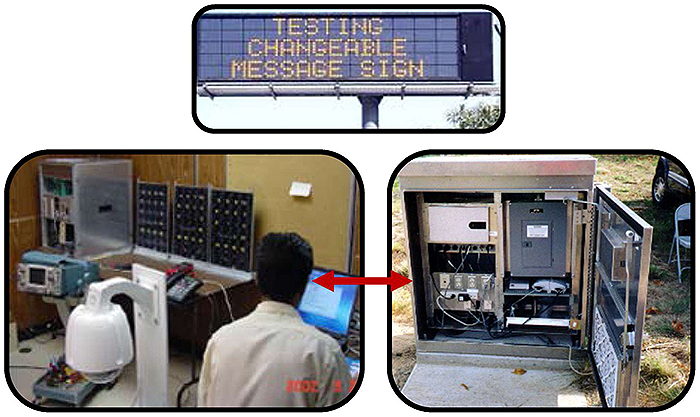
(Extended Text Description: This slide contains the title "Module T311: Applying Your Test Plan to the NTCIP 1203 v03 DMS Standard" and also consists of a picture of a dynamic message sign directly below the title. Two more pictures are underneath the picture of the dynamic message sign. The left picture shows a control center room with an employee looking at his computer monitor with several dynamic message sign display boards on a table, and the right pictures shows a roadside sign controller cabinet mounted on the ground with the door open. These two pictures are connected with a red double ended arrow implying a communication line between the sign controller cabinet and the control center.)
Slide 4:
Instructor

Patrick Chan, PE
Senior Technical Staff
Consensus Systems Technologies (ConSysTec)
Flushing, NY, USA
Slide 5:
Learning Objectives
- Describe within the context of a testing lifecycle the role of a test plan and the testing to be undertaken for DMS
- Identify the key elements of NTCIP 1203 v03 relevant to the test plan
- Describe the application of a good test plan to a DMS system being procured
- Describe a process of adapting a test plan based on the selected user needs and requirements
Slide 6:
Learning Objective 1
- Describe within the context of a testing lifecycle the role of a test plan and the testing to be undertaken for DMS
Slide 7:
Why Do We Test?
Why This Module?
- As a procurer, operator or specification writer of dynamic message signs, need a method to check that the system provided fulfills all your requirements
- This module will walk through the elements on how to test!
-
Develop a test plan that:
- Checks your requirements have been fulfilled
- Satisfies your (agency's) specific needs
- Conforms to the appropriate standards
Slide 8:
Why Do We Test?
Why Test?
-
Verify the system meets the procurement specification and fulfills the requirements (Was the system built right?)
- Requirements discussed in Module A311b: Specifying Requirements for DMS Based on NTCIP 1203 Standard
-
Validate that the system satisfies the user and operational needs (Did you build the right system?)
- User needs discussed in Module A311b: Understanding User Needs for DMS Systems Based on NTCIP 1203 Standard

Slide 9:
Why Do We Test?
Why Test?
-
Test for conformance to the NTCIP 1203 Standard -achieve off-the-shelf Interoperability
- Interoperability: Ability of two or more systems or components to exchange information and use the information that has been exchanged
- NTCIP 1203 supports interoperability for dynamic message sign systems!

(Extended Text Description: Author's relevant description: There are two photos on the bottom of the slide: on the left, a photo of a traffic control center with an employee and various computer monitors and screens, on the right, a photo of a large dynamic message sign. The two photos have a black, doubled headed arrow between them with "NTCIP 1203" written above it, demonstrating interoperability by this standard.)
Source: NYCDOT
Slide 10:
Why Do We Test?
The Vee Model
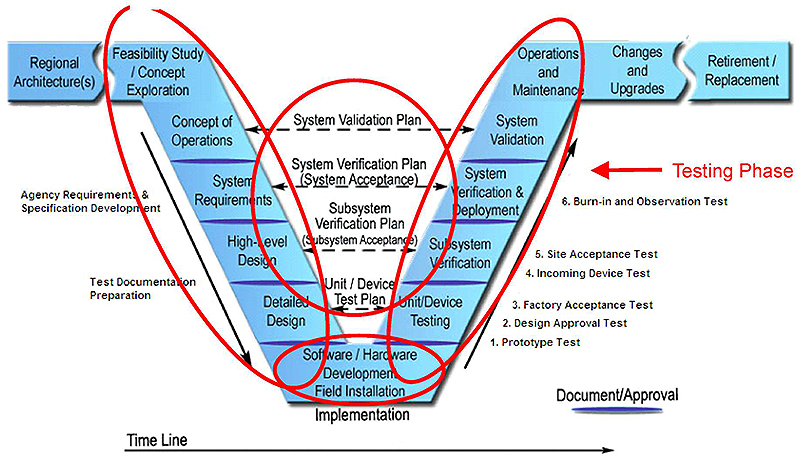
(Extended Text Description: A figure with a diagram in the shape of a "VEE" with flanges. On the left-most flange of the "VEE" diagram is Regional ITS Architecture(s), followed by Feasibility Study / Concept Exploration. Going down the left-side of the "VEE" diagram is Concept of Operations, followed by a Document/Approval marker, followed by Systems Requirements, followed by a Document/Approval marker, followed by High-Level Design, followed by a Document/Approval marker, followed by Detailed Design, followed by a Document/Approval marker, and Software / Hardware Development Field Installation at the bottom of the "VEE" diagram. Going up the right-side of the "VEE" diagram is a Document/Approval marker, followed by Unit/Device Testing, followed by a Document/Approval marker, followed by Subsystem Verification, followed by a Document/Approval marker, followed by System Verification & Deployment, followed by a Document/Approval marker, followed by System Validation, and followed by Operations and Maintenance. Continuing along the right flange of the VEE diagram is Changes and Upgrades, followed by Retirement / Replacement. Between Concept of Operations (on the left side of the VEE) and System Validation (on the right side of the VEE) is a bi-directional dotted line labeled System Validation Plan. Continuing down the VEE diagram is a bi-directional dotted line labeled System Verification Plan (System Acceptance) between System Requirements and System Verification & Deployment. Continuing down the VEE diagram is a bi-directional dotted line labeled Subsystem Verification Plan (Subsystem Acceptance) between High-Level Design and Subsystem Verification. Continuing down the VEE diagram is a bi-directional dotted line labeled Unit / Device Test Plan between Detailed Design and Unit/Device Testing. There is an arrow pointing down parallel to the left side of the VEE diagram, with the text Agency Requirements and Specification Development adjacent to System Requirements, and the text Test Document Preparation adjacent to High-Level Design and Detailed Design. There is an arrow labeled Time Line at the bottom of the VEE diagram pointing from left to right. Finally, there is an arrow pointing up the right side of the VEE diagram, with the text Prototype Test, followed by Design Approval Test, followed by Factory Acceptance Test adjacent to Unit/Device Testing; and the text Incoming Device Test followed by Site Acceptance Test adjacent to Subsystem Verification; and the text Burn-in and Observation Test adjacent to System Verification & Deployment. Circled in red is the left side, right side, and bottom of the "VEE" and also the middle bi-directional dotted lines. On the right side of the slide there is a red arrow pointing to the "System Verification & Deployment" stage of the "VEE" with "Testing Phase" written in red next to it. At the bottom, right-hand corner is a clip art graphic of a black speech bubble with a white "i" inside of it, representing Background Information.)

Slide 11:
Why Do We Test?
Verification
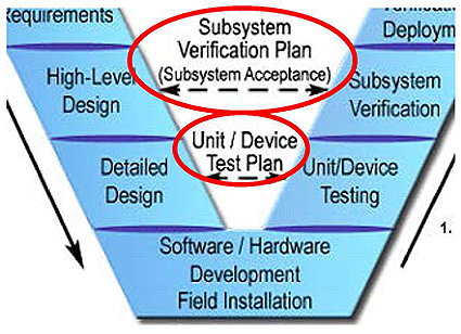
(Extended Text Description: A figure showing the bottom half of the "VEE" diagram that was previously depicted in Slide #10. Going down the left-side of the "VEE" diagram is High-Level Design, followed by a Document/Approval marker, followed by Detailed Design, followed by a Document/Approval marker, and Software / Hardware Development Field Installation at the bottom of the "VEE" diagram. Going up the right-side of the "VEE" diagram is a Document/Approval marker, followed by Unit/Device Testing, followed by a Document/Approval marker, followed by Subsystem Verification. Between High-Level Design (on the left side of the VEE) and Subsystem Verification (on the right side of the VEE) is a bi-directional dotted line labeled Subsystem Verification Plan (Subsystem Acceptance). Continuing down the VEE diagram is a bi-directional dotted line labeled Unit / Device Test Plan between Detailed Design and Unit/Device Testing. There is an arrow pointing up the right side of the VEE diagram, with the text Prototype Test, followed by Design Approval Test, followed by Factory Acceptance Test adjacent to Unit/Device Testing; and the text Incoming Device Test followed by Site Acceptance Test adjacent to Subsystem Verification. The bi-directional dotted lines in the middle of the bottom of the "VEE" are circled in red.)
-
Subsystem Verification - Verify functionality over the installed communications systems using NTCIP 1203
- E.g., Tests a DMS and its immediate environment, including the cabinet, power supply, and communications equipment
-
Unit/Device Testing -Verify functionality at the DMS itself
- e.g., Tests a standalone DMS
Slide 12:
Why Do We Test?
Verification

(Extended Text Description: A figure showing the top half of the "VEE" diagram that was previously depicted in Slide #10. On the left-most flange of the "VEE" diagram is Regional ITS Architecture(s), followed by Feasibility Study / Concept Exploration. Going down the left-side of the "VEE" diagram is Concept of Operations, followed by a Document/Approval marker, followed by Systems Requirements, followed by Document/Approval marker. Going up the right-side of the "VEE" diagram is a Document/Approval marker, followed by System Verification & Deployment, followed by a Document/Approval marker, followed by System Validation, and followed by Operations and Maintenance. Continuing along the right flange of the VEE diagram is Changes and Upgrades, followed by Retirement / Replacement. Between Concept of Operations (on the left side of the VEE) and System Validation (on the right side of the VEE) is a bi-directional dotted line labeled System Validation Plan. Continuing down the VEE diagram is a bi-directional dotted line labeled System Verification Plan (System Acceptance) between System Requirements and System Verification & Deployment. There is an arrow pointing down parallel to the left side of the VEE diagram, with the text Agency Requirements and Specification Development adjacent to System Requirements. There is an arrow pointing up the right side of the VEE diagram, with the text Burn-in and Observation Test adjacent to System Verification & Deployment. The middle bi-directional dotted line labeled "System Verification Plan (System Acceptance)" is circled in red.)
-
System Verification - Verify functionality, using the TMC software, over the installed communications systems.
- e.g., Tests the entire DMS system, including the Traffic Management Center (TMC) software.
Slide 13:
Why Do We Test?
Validation

(Extended Text Description: A figure showing less of the top half of the "VEE" diagram that was previously depicted in Slide #12. On the left-most flange of the "VEE" diagram is Regional ITS Architecture(s), followed by Feasibility Study / Concept Exploration. Going down the left-side of the "VEE" diagram is Concept of Operations. Going up the right-side of the "VEE" diagram is System Validation followed by Operations and Maintenance. Continuing along the right flange of the VEE diagram is Changes and Upgrades, followed by Retirement / Replacement. Between Concept of Operations (on the left side of the VEE) and System Validation (on the right side of the VEE) is a bi-directional dotted line labeled "System Validation Plan" which is circled in red.)
- System Validation - confirms that the system, as built, satisfies the stakeholder's stated needs.
-
The system is validated when:
- Approved by the agency and the key stakeholders.
- All the project requirements are fulfilled.
- Corrective actions have been implemented for any anomalies that have been detected.
Slide 14:
Purpose of a Test Plan
Test Plan
- Test Plan - Documents and identifies the testing activities
-
High-level document that identifies:
- What item is to be tested?
- How is the item to be tested?
- Who is to test the item?
- In what detail is the item to be tested?
- What are the test deliverables?
- When is the testing to take place?
- Test Plans are defined in IEEE 829-2008
- Module T201 - How to Write a Test Plan
Slide 15:
Purpose of a Test Plan
Test Plan Items
-
What is being tested?
-
Identifies the scope of the test plan
- Is it just the dynamic message signs? Which ones?
- There may be a separate test plan for each type of testing or DMS OR it may be one single test plan for the entire system
-
Identifies the scope of the test plan

(Extended Text Description: Author's relevant description: At the bottom left hand corner of this slide is a picture of a traffic signal with a blank out sign immediately above it. The blank out sign contains the words "No Left Turn." At the bottom right hand corner of this slide are two clip art graphics, one of a changeable message sign with three rows and another of a 3-line matrix variable message sign.)
Slide 16:
Purpose of a Test Plan
Test Plan Items
-
How is the item to be tested?
- Identifies the test environment
- NTCIP testing typically takes the form of interface testing
- May require specialized equipment to simulate environmental conditions

(Extended Text Description: Author's relevant description: A figure with a graphic depicting a device, labeled Device Under Test (DUT), with a bi-directional line to a cloud, labeled Communications. From the cloud labeled Communications is a bi-directional ling to a graphic of a laptop computer, labeled Test Software. Also, there is a loop connecting the cloud labeled Communications and a different graphic of a laptop computer labeled Data Analyzer (Optional).)
Slide 17:
Purpose of a Test Plan
Test Plan Items
-
Who is to test the items?
-
Identifies the roles and responsibilities for each person in managing, designing, preparing, executing, and resolving
- Potential conflicts of interest: Vendor wants a quick test to meet payment; agency wants a thorough test to assure years of useful service
-
Identifies the roles and responsibilities for each person in managing, designing, preparing, executing, and resolving

Slide 18:
Purpose of a Test Plan
Test Plan Items
-
In what detail will the items will be tested?
- Permit identification of the major testing tasks and estimation of time
- Trace the requirements to be tested
- Identify significant constraints, such as item availability, resource availability, and deadlines

Slide 19:
Purpose of a Test Plan
Test Plan Items
-
What are the Test Deliverables?
- Test Plans
- Test Logs
- Test Summary Reports
- Identifies the testing milestones, including submittals, time to perform each task, and testing resources

Slide 20:
Components of a Test Plan
A well-written test plan consists of [IEEE 829-2008]:
- Test Design Specification. Specifies the details of the test approach for a feature or combination of features and identifies the test case specifications to be performed
- Test Case Specification. Specifies the inputs, predicted results, a set of execution conditions and the pass/fail criteria for the test item
- Test Procedure Specification. Specifies a sequence of actions for the execution of a test
Slide 21:
Components of a Test Plan
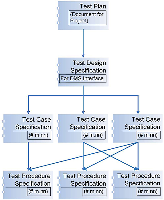
(Extended Text Description: Author's relevant description: A figure with a chart depicting the components of a test plan. At the top of the chart is a box with the text, Test Plan (Document for Project), pointing to a box on the second row with the text, Test Design Specification (For DMS Interface), pointing to three boxes on the third row, each with the text, Test Case Specification #m, nn. Each box on the third-row points to one or more boxes on the fourth row. Each box on the fourth row has the text Test Procedure Specification #m, nn.)
- A test plan may consist of several test design specifications
- There may be a separate test design specification for each implementation
- Each test design specification may consist of several test cases and test procedures
Slide 22:

Slide 23:
Question
What does a "test case specification" do? Answer Choices
- Specifies the inputs, predicted results, and the conditions for one or more functions in the test item
- Specifies the details of the test approach for a feature or combination of features
- Describes the scope, approach, and resources for the testing activities
- Specifies the sequence of actions for the execution of a test
Slide 24:
Review of Answers
 a) Specifies the inputs, predicted results, and the conditions for one or more functions in the test item
Correct! A test case does all of the above.
 b) Specifies the details of the test approach for a feature or combination of features
Incorrect. This describes a test design specification.
 c) Describes the scope, approach, and resources for the testing activities
Incorrect. This describes a test plan.
 d) Specifies the sequence of actions for the execution of a test
Incorrect. This defines a test procedure specification.
Slide 25:
Learning Objectives
- Describe within the context of a testing lifecycle the role of a test plan and the testing to be undertaken for DMS
- Identify the key elements of NTCIP 1203 v03 relevant to the test plan
Slide 26:
Learning Objective 2
- Identify the key elements of NTCIP 1203 v03 relevant to the test plan
Slide 27:
What Is Being Tested?
NTCIP 1203
-
What is NTCIP 1203?
- Is a communications interface standard
- Specifies the interface between the dynamic message signs in the field and the host systems that control them
- Contains the object definitions (vocabulary) that allow for the monitoring and control of dynamic message signs

Slide 28:
What Is Being Tested?
NTCIP 1203
- NTCIP 1203 v01 (1999)
- NTCIP 1203 Amendment 1 (2001)
-
NTCIP 1203 v02 (2010)
- Added new functionality and systems engineering content
-
NTCIP 1203 v03 (2014)
-
Adds Test Cases and Test Procedures
- Allows agencies procuring DMS systems to consistently test for conformance to the DMS Standards
-
Adds Test Cases and Test Procedures

Slide 29:
What Is Being Tested?
Interface/Communications Testing
- Compliance with the procurement specification
-
Conformance with the NTCIP Standard
- The Protocol Requirements List (PRL) defines the user needs and requirements for a procurement specification
- The DMS system must fulfill the mandatory requirements and other specified (selected optional) requirements of NTCIP 1203 and the standards it references.
- Conformance is NOT compliance!
Slide 30:
What Is Being Tested?
Interface/Communications Testing
-
Communications requirements are fulfilled
-
The Requirements Traceability Matrix (RTM) in NTCIP 1203 defines the manner to fulfill a standard requirement
- Do the data exchanges (Dialogs) occur as defined by the standard?
- Are all the data objects used as defined by the standard?
-
The Requirements Traceability Matrix (RTM) in NTCIP 1203 defines the manner to fulfill a standard requirement
- Functional requirements are fulfilled
- Performance requirements
Slide 31:
Test Cases and Test Procedures in NTCIP 1203 v03
RTCTM
NTCIP 1203 v03 provides a Requirements to Test Case Traceability Matrix (RTCTM)
- Lists the test case(s) that must be passed to fully test whether a requirement has been fulfilled by the implementation

Slide 32:
Test Cases and Test Procedures in NTCIP 1203 v03
RTCTM
For the requirement "Activate Pixel Testing," both test case C.3.5.1 and C.3.5.2 must be passed to verify the requirement.
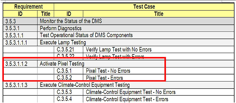
(Extended Text Description: The figure is a snapshot of a Requirements – Test Case Traceability Matrix (RTCTM) table. Requirement ID 3.5.3.1.1.2, Activate Pixel Testing is highlighted in a red box, along with the two test cases beneath it, C.3.5.1 Pixel Test - No Errors, and C.3.5.2, Pixel Test - Errors. The full table is located below:
| Requirement | Test Case | ||
|---|---|---|---|
| ID | Title | ID | Title |
| 3.5.3 | Monitor the Status of the DMS | ||
| 3.5.3.1 | Perform Diagnostics | ||
| 3.5.3.1.1 | Test Operational Status of DMS Components | ||
| 3.5.3.1.1.1 | Execute Lamp Testing | ||
| C.3.5.21 | Verify Lamp Test with No Errors | ||
| C.3.5.22 | Verify Lamp Test with Errors | ||
| 3.5.3.1.1.2 | Activate Pixel Testing | ||
| C.3.5.1 | Pixel Test - No Errors | ||
| C.3.5.2 | Pixel Test - Errors | ||
| 3.5.3.1.1.3 | Execute Climate-Control Equipment Testing | ||
| C.3.5.3 | Climate-Control Equipment Test - No Errors | ||
| C.3.5.4 | Climate-Control Equipment Test - Errors | ||
)
Source: NTCIP 1203 v03, Volume I.
Slide 33:
Test Cases and Test Procedures in NTCIP 1203 v03
RTCTM
-
Multiple test cases may be needed to completely test a requirement
- Each test case may test different conditions - e.g., there are separate test cases for "no errors are detected" and for "an error was reported for a pixel test"
- Each test case may test a different set of values - e.g., there are separate test cases to verify left, center, and right justification
- An implementation must pass all test cases that the requirement traces to before claiming that the requirement is fulfilled
Slide 34:
Test Cases and Test Procedures in NTCIP 1203 v03
Test Case Specifications
Test Case Specification. A document specifying inputs, predicted results, and execution conditions. This information can be found in the header of each table.
- An agency may wish to perform a test case specification multiple times, each iteration with a different input and different expected output.
- A test case specification needs to be performed only once to verify CONFORMANCE to the standard, however more instances may be required to verify COMPLIANCE with the project specifications.
- May wish to perform negative (exception) testing -e.g., invalid values - to verify DMS behavior.

Slide 35:
Test Cases and Test Procedures in NTCIP 1203 v03
Test Case Specifications
If the project specification requires that a DMS comes preconfigured with three fonts, Test Case C.3.2.4, Retrieve a Font Definition, might be performed three times, once for each font.
3.5.1.3.4 Retrieve a Font Definition
The DMS shall allow a management station to upload the fonts defined in the sign controller.
| Requirement | Test Case | ||
|---|---|---|---|
| ID | Title | ID | Title |
| 3.5.1.3.4 | Retrieve a Font Definition | ||
| C.3.2.4 | Retrieve a Font Definition | ||
Source: NTCIP 1203 v03, Volume II.

Slide 36:
Test Cases and Test Procedures in NTCIP 1203 v03
Test Case Specifications
- Can be used for NTCIP 1203 v01 and v02 systems!

(Extended Text Description: This slide contains a snapshot of the test case specification for Test Case C.3.5.1 Pixel Test - No Errors. There are 3 red vertical rectangles highlighting the Description, Variables, and the Pass/Fail Criteria. The table is located below:
C.3.5.1 Pixel Test - No Errors
| Test Case: 5.1 | Title: | Pixel Test - No Errors | |
| Description: | This test case verifies that the DMS executes a pixel test and verifies that there are no failed pixels. | ||
| Variables: | Pixel_Test_Time | From Manufacturer's Documentation | |
| Message_Display_Test_Time | From Manufacturer's Documentation | ||
| Pass/Fail Criteria: | The DUT shall pass every verification step included within the Test Case to pass the Test Case. | ||
)
Source: NTCIP 1203 v03, Volume II.
Slide 37:
Test Cases and Test Procedures in NTCIP 1203 v03
Test Procedure Specifications
-
Test Procedure Specification. A document that contains the sequence of actions for the execution of a test.
- Only defines the steps necessary to test the function.
-
Standard test procedures ensure that the conformance testing is performed in the same manner on separate test occasions.
- A test procedure in a test case specification may be "called" by another test procedure in a different test case specification.
- It is important not to skip any steps in the test procedui to ensure proper conformance testing.

Slide 38:
Test Cases and Test Procedures in NTCIP 1203 v03
Test Procedure Specifications
- NTCIP 1203 v03 combines test cases and test procedures into one test case.

(Extended Text Description: Author's relevant description: This slide is a snapshot of the same test case specification in Slide #36, but expanded to also show the first step of the test procedures. A red rectangle highlights the test case specification information, and a second rectangle highlights the test procedure specification information. The additional expanded test procedure is shown below:
| Step | Test Procedure | Results | Additional References |
|---|---|---|---|
| 1 | CONFIGURE: Determine the maximum period of time that the pixel test should require (based on manufacturer documentation). RECORD this information as: »Pixel_Test_Time |
)
Slide 39:
Test Cases and Test Procedures in NTCIP 1203 v03
Test Procedure Specifications

(Extended Text Description: This slide contains a snapshot of the test procedure specification, for Steps 1 to 5. Steps 1 to 6 are highlighted with a red rectangle. Step 4 contains the text, "Pass/Fail (Section 3.5.3.1.1.2)" in the Results column and the text "Section 4.2.4.2, Step a" in the Additional References column. These two cells in Step 4 are highlighted in a second red rectangle. The tabel is located below:
| Step | Test Procedure | Results | Additional References |
|---|---|---|---|
| 1 | CONFIGURE: Determine the maximum period of time that the pixel test should require (based on manufacturer documentation). RECORD this information as: »Pixel_Test_Time | ||
| 2 | CONFIGURE: Determine the maximum period of time that the message display pixel test should require (based on manufacturer documentation). RECORD this information as: »Message_Display_Test_Time | ||
| 3 | SET-UP: Ensure that all pixels are functioning prior to this test. | ||
| 4 |
SET the following object(s) to the value(s) shown: »pixelTestActivation.0 = 'test' (3) NOTE--Valid enumerated values are defined in Section 5.11.2.4.3 (Pixel Test Activation Parameter). |
Pass / Fail (Section 3.5.3.1.1.2) | Section 4.2.4.2 Step a |
| 5 | GET the following object(s): »pixelTestActivation.0 | Pass / Fail (RFC 1157) | Section 4.2.4.2 Step b |
| 6 |
IF the RESPONSE VALUE for pixelTestActivation.0 equals 'test' (3), then GOTO Step 5; otherwise, GOTO Step 7. NOTE--If the RESPONSE VALUE remains at 'test' (3) for more than Pixel_Test_Time seconds, this test fails. |
)
Source: NTCIP 1203 v03, Volume II.
Slide 40:
Test Cases and Test Procedures in NTCIP 1203 v03
Test Procedure Specifications
- CONFIGURE. Indicates the test step as a predicate to identify a configurable variable.
- SET-UP. Indicates the test step is a preparatory step to set up the environment for the actual test.

(Extended Text Description: This slide contains a snapshot of the first and second columns of a partial test procedure specification. There are three red rectangles on the slide, each highlighting text in the test procedure. The table is located below:
| 1 |
CONFIGURE: Determine the enumerated value corresponding to the beacon type required by the specification (PRL 2.3.2.4). RECORD this information as: »Required_Beacon_Type NOTE-Valid enumerated values are defined in Section 5.2.8 (Beacon Type Parameter). |
| 2 | SET-UP: Determine the enumerated value indicating the actual type of beacons on the sign (See Section 5.2.8). RECORD this information as: »Actual_Beacon_Type |
)
Source: NTCIP 1203 v03, Volume II.
Slide 41:
Test Cases and Test Procedures in NTCIP 1203 v03
Test Procedure Specifications
Output Specifications
- What are the expected values/output?
- E.g., VERIFY that the RESPONSE VALUE for shortErrorStatus.0 has bit 5 cleared

(Extended Text Description: This slide contains a snapshot of the bottom portion of the test procedure specification, followed immediately by the bottom of the test case specification. Step 17 and the test procedure text, "VERIFY that the RESPONSE VALUE for shortErrorStatus.0 has bit 5 (pixel error) cleared" is highlighted in a red rectangle. The table is located below:
| 17 | VERIFY that the RESPONSE VALUE for shortErrorStatus.0 has bit 5 (pixel error) cleared. | Pass / Fail (Section 3.5.3.1.2) | |
| 18 | PERFORM the test case labeled 'Blank the Sign' (C.3.7.15). | Pass / Fail (Section 3.5.2.3.1) |
| Test Case Results | |
| Tested By: Date Tested: | Pass / Fail |
| Test Case Notes: | |
)
Source: NTCIP 1203 v03, Volume II.
Slide 42:
Test Cases and Test Procedures in NTCIP 1203 v03
Test Procedure Specifications
Intercase Dependencies
- Identify any test cases to be performed during this test case.
- E.g., PERFORM the test case labeled...

(Extended Text Description: This slide contains the same snapshot in Slide #41 - the bottom portion of the test procedure specification, followed immediately by the bottom of the test case specification. However, Step 18 and the test procedure text, "PERFORM the test case labeled 'Blank the Sign' (C.3.7.15)" is highlighted in a red rectangle.)
Source: NTCIP 1203 v03, Volume II.
Slide 43:

Slide 44:
Question
What is the purpose of the Requirements to Test Case Matrix?
Answer Choices
- Identify the requirements that are part of the project specification
- Identify all the test cases that must be passed to verify a requirement is fulfilled
- Identify the design content to fulfill a requirement
- Identify one of the possible test cases that must be passed to verify a requirement is fulfilled
Slide 45:
Review of Answers
 a) Identify the requirements that are part of the project specification
Incorrect. The Protocol Requirements List (PRL) identifies the requirements that are part of a project specification.
 b) Identify all the test cases that must be passed to verify a requirement is fulfilled
Correct! The RTCTM identifies all the test cases that must be passed to verify a requirement is fulfilled.
 c) Identify the design content to fulfill a requirement
Incorrect. The Requirements Traceability Matrix identifies the design content to fulfill a requirement.
 d) Identify one of the possible test cases that must be passed to verify a requirement is fulfilled
Incorrect. All the test cases traced to a requirement must be passed to verify the requirement is fulfilled.
Slide 46:
Learning Objectives
- Describe within the context of a testing lifecycle the role of a test plan and the testing to be undertaken for DMS
- Identify the key elements of NTCIP 1203 v03 relevant to the test plan
- Describe the application of a good test plan to a DMS system being procured
Slide 47:
Learning Objective 3
- Describe the application of a good test plan to a DMS system being procured
Slide 48:
Test Plan for a DMS System
Introduction and Test Items
[IEEE 829-2008]
- Test Plan Identifier
-
Introduction:
- Purpose: Verify compliance to the Procurement No. 11-xxx, and verify conformance to NTCIP 1203 v03
-
Test Items:
- ATMS software, Build yy;
- 5 Blank Out Signs - Procurement No. 11-xxx
- 5 VMSs (3 lines x 24 characters) - Procurement No. 11-xxx

Slide 49:
Test Plan for a DMS System
Features Being Tested and Approach
-
Features to be tested
-
Can just be a copy of the completed Protocol Requirements List (PRL)
- User needs and requirements selected for the project
-
Can just be a copy of the completed Protocol Requirements List (PRL)
- Features not to be tested
- Approach - Discussion of how the tests are organized and how the results are logged
-
Items pass/fail
- To pass the test, the item under test shall pass all test procedures associated with requirements for the test item

Slide 50:
Test Plan for a DMS System
Features Being Tested and Approach
- Suspension criteria and resumption requirements
-
Test deliverables
- Test plan, test log reports, test summary reports
- Testing tasks
-
Environmental needs
- Test environment (facility, software programs, firmware version), test item hardware (power supplies, DMS components), test hardware (protocol analyzer), communications (RS-232 cables, Ethernet connections)

Slide 51:
Test Plan for a DMS System
Responsibilities, Schedule, and Approvals
-
Responsibilities
- The agency will design, prepare and execute the tests
- The consultant will manage, review, and witness the tests
- The vendor will witness the tests and provide repairs to anomalies
- Staffing and training needs
- Schedule
- Risks and contingencies
-
Approvals
- Names and titles of all persons to approve this plan

Slide 52:

Slide 53:
Question
Which of the following information is not provided in a test plan?
Answer Choices
- What item is being tested?
- Who is responsible for performing the test?
- What are the inputs and outputs for the test case specification?
- What are the test deliverables?
Slide 54:
Review of Answers
 a) What item is being tested?
Incorrect A test plan identifies the test item.
 b) Who is responsible for performing the test?
Incorrect. A test plan identifies the roles and responsibilities of the persons involved with the test.
 c) What are the inputs and outputs for a test case?
Correct! The inputs and outputs for a test case is defined in a test case specification.
 d) What are the test deliverables?
Incorrect. A test plan does identify the deliverables of the testing, such as test documentation.
Slide 55:
Learning Objectives
- Describe within the context of a testing lifecycle the role of a test plan and the testing to be undertaken for DMS
- Identify the key elements of NTCIP 1203 v03 relevant to the test plan
- Describe the application of a good test plan to a DMS system being procured
- Describe a process of adapting a test plan based on the selected user needs and requirements
Slide 56:
Learning Objective 4
- Describe a process of adapting a test plan based on the selected user needs and requirements
Slide 57:
Develop a Test Design Specification Based on NTCIP 1203 v03
Definition
-
Test Design Specification. Identifies the features to be covered by the design and its associated tests. It also identifies the test cases and test procedures required to accomplish the testing and specifies the pass/fail criteria.
- For example, Test Design Specifications for color variable message signs and blank-out signs.


Slide 58:
Develop a Test Design Specification Based on NTCIP 1203 v03
Features to Be Tested
-
NTCIP 1203 v02 and v03
- The completed PRL indicates what features and requirements have been selected for the procurement specification.
- Those requirements should be tested as part of the test plan.

(Extended Text Description: This slide contains a snapshot of a partial Protocol Requirements List (PRL) that has been completed. The user need, 2.5.2.3.1, Activate and Display a Message, has a "M" in the Conformance column, and the word "Yes" under the Support/Project Requirement is circled in red. Under this user need are two requirements, 3.5.2.3.1 - Activate a Message and 3.5.2.3.3.5 - Retrieve a Message. Both requirements have a "M" in the Conformance column, and the word "Yes" under the Support/Project Requirement is circled in red. A third requirement is found under the user need, 3.5.2.3.6, Activate a Message with Status, with a "Drum:M" in the Conformance column, with the words "Yes / NA" in the Support/Project Requirement column, and the word "Yes" circled in red. The table is located below:
| UN Section Number | User Need (UN) | FR Section Number | Functional Requirement (FR) | Conformance | Support/ Project Requirement | Additional Project Requirements |
|---|---|---|---|---|---|---|
| 2.5.2.3.1 | Activate and Display a Message | M | Yes | |||
| 3.5.2.3.1 | Activate a Message | M | Yes | |||
| 3.5.2.3.3.5 | Retrieve Message | M | Yes | |||
| 3.5.2.3.6 | Activate a Message with Status | Drum:M | Yes / NA | |||
)
Slide 59:
Develop a Test Design Specification Based on NTCIP 1203 v03
Features to Be Tested
-
For example, "Activate Pixel Testing" is a selected requirement in the completed PRL
- See Student Supplement for the full description

(Extended Text Description: This slide contains a snapshot of a partial Protocol Requirements List (PRL) that has been completed. Under the user need, 2.5.3.1.1 - Determine Sign Error Conditions - High-Level Diagnostics, are four requirements. FR ID 3.5.3.1.1.1 - Execute Lamp Testing, has a "Lamp OR Fiber:M" in the Conformance column, and the words "Yes / NA" under the Support/Project Requirement, with NA is circled in red. FR ID 3.5.3.1.1.2 - Activate Pixel Testing, has a "Matrix:M" in the Conformance column, and the word "Yes" under the Support/Project Requirement circled in red. The entire row with the Activate Pixel Testing requirement is also circled in red. FR ID 3.5.3.1.1.3 - Execute Climate-Control Equipment Testing, has a "O" in the Conformance column, and the words "Yes / No" under the Support/Project Requirement, with Yes is circled in red. The table is located below:
| USER NEED SECTION NUMBER | USER NEED | FR SECTION NUMBER | FUNCTIONAL REQUIREMENT | CONFORMANCE | SUPPORT/ PROJECT REQUIREMENT | ADDITIONAL PROJECT REQUIREMENTS |
|---|---|---|---|---|---|---|
| 2.5.3 | Monitor the Status of the DMS | M | Yes | |||
| 2.5.3.1 | Perform Diagnostics | M | Yes | |||
| 2.5.3.1.1 | Determine Sign Error Conditions - High-Level Diagnostics | M | Yes | |||
| 3.5.3.1.1.1 (LampTest) | Execute Lamp Testing | Lamp OR Fiber:M | Yes / NA | |||
| 3.5.3.1.1.2 (PixelTest) | Activate Pixel Testing | Matrix :M | Yes / NA | |||
| 3.5.3.1.1.3 (ClimateTest) | Execute Climate-Control Equipment Testing | 0 | Yes / No | |||
| 3.5.3.1.2 | Provide General DMS Error Status Information | M | Yes | |||
)
Source: NTCIP 1203 v03, Volume /.

Slide 60:
Develop a Test Design Specification Based on NTCIP 1203 v03
Requirements Traceability Matrix
-
The Requirements Traceability Matrix (RTM) defines the dialogs and data objects that must be used to fulfill the requirement.
- The dialogs are the sequence of data exchanges (and events) that are defined by the standard.
- Conformance testing confirms that the DMS system performs the same sequence of data exchanges (and events) as defined in the standard (and referenced standards).
Slide 61:
Develop a Test Design Specification Based on NTCIP 1203 v03
Requirements Traceability Matrix
The RTM defines the dialog and object needed to fulfill the requirement "Activate Pixel Testing."

(Extended Text Description: This slide contains a snapshot of a partial Requirement Traceability Matrix. The requirement, FR ID 3.5.3.1.1.2, Activate Pixel Testing, is circled in red, along with Dialog ID 4.2.4.2 on the same row, and Object ID 5.11.2.4.3, Object Name pixelTestActivation on the row beneath the functional requirement. The table is located below:
| Requirements Traceability Matrix (RTM) | |||||
| FR ID | Functional Requirement | Dialog ID | Object ID | Object Name | Additional Specifications |
|---|---|---|---|---|---|
| 3.5.3 | Monitor the Status of the DMS | ||||
| 3.5.3.1 | Perform C agnostics | ||||
| 3.5.3.1.1 | Test Operational Status of DMS Components | ||||
| 3.5.3.1.1.1 | Execute Lamp Testing | 4.2.4.1 | |||
| 5.11.2.5.3 | lampTestActivation | ||||
| 3.5.3 1.1.2 | Activate Pixel Testing | 4.2.4.2 | |||
| 5.11.2.4.3 | pixelTestActivation | ||||
| 3.5.3.1.1.3 | Execute Climate-Control Equipment Testing | 4.2.4.3 | |||
| 5.11.2.3.5.6 | dmsClimateCtrlTestActivation | ||||
| 5.11.2.3.5.7 | dmsClimateCtrlAbortReason | ||||
)
Source: NTCIP 1203 v03, Volume /.
Slide 62:
Develop a Test Design Specification Based on NTCIP 1203 v03
Requirements Traceability Matrix
Below is the dialog that fulfills the requirement Activate Pixel Testing
4.2.4.2 Activating Pixel Testing
The standardized dialog for a management station to command the DMS to activate pixel testing shall be as follows:

(Extended Text Description: This slide contains a snapshot of Section (Dialog) 4.2.4.2 Activating Pixel Testing from NTCIP 1203 v03. The dialog consists of three steps, labeled a, b, and c. Each step is circled in red.
- The management station shall SET pixelTestActivation.O to 'test'.
- The management station shall repeatedly GET pixelTestActivation.O until it either returns the value of 'noTest' or a maximum time-out is reached. If the time-out is reached, the DMS is apparently locked and the management station shall exit the process.
-
(Postcondition) The following objects will have been updated during the pixel test to reflect current conditions. The management station may GET any of these objects as appropriate.
- pixelFailureTableNumRows
- any object within the pixelFailureTable
)
Source: NTCIP 1203 v03, Volume /.
Slide 63:
Develop a Test Design Specification Based on NTCIP 1203 v03
Requirements to Test Case Traceability Matrix
- Based on the project requirements selected in the PRL, an agency can create a RTCTM containing only those selected requirements and their associated test cases.
| Requirement | Test Case | ||
|---|---|---|---|
| ID | Title | ID | Title |
| 3.5.3 | Monitor the Status of the DMS | ||
| 3.5.3.1 | Perform Diagnostics | ||
| 3.5.3.1.1 | Test Operational Status of DMS Components | ||
| 3.5.3.1.1.1 | Execute Lamp Testing | ||
| 3.5.3.1.1.2 | Activate Pixel Testing | ||
| C.3.5.1 | Pixel Test - No Errors | ||
| C.3.5.2 | Pixel Test - Errors | ||
| 3.5.3.1.1.3 | Execute Climate-Control Equipment Testing | ||
| C.3.5.3 | Climate-Control Equipment Test - No Errors | ||
| C.3.5.4 | Climate-Control Equipment Test - Errors | ||
Slide 64:
Develop a Test Design Specification Based on NTCIP 1203 v03
Requirements to Test Case Traceability Matrix
-
The tailored RTCTM becomes part of the test design specification.
- Identifies the requirements to be tested.
- Identifies the test cases and test procedures to be performed.
Slide 65:
Test Design Specification
Test Design Specification
-
Test Design Specification (TDS) identifier
- One TDS for the blank out signs
- One TDS for the VMSs
-
Features to be tested
- Copy of the completed PRL for the specific test item (e.g., one PRL for the BOS, one PRL for the VMS)
- Approach refinements
-
Test identification
- Tailored RTCTM
- Feature pass/fail criteria

Slide 66:
How to Develop Test Cases and Test Procedures for Extensions
Extensions
- Extensions - to support agency-specific features and/or requirements not supported by the standard
-
Permitted but not encouraged
- Interoperability is not achieved
Slide 67:
How to Develop Test Cases and Test Procedures for Extensions
Extensions
-
For communication interface features not covered by the standard, procurers should document and clearly define:
- The user need/feature
- Customized requirements to satisfy the new user need
- The dialogs and objects to fulfill each customized requirement
- Test cases should be created for testing the customized requirements
- The identifier of the customized requirements and test cases should be included in the tailored RTCTM and the test design specification
Slide 68:
How to Use the Test Procedure Generator Tool
Test Procedure Generator (TPG)
-
Free tool from USDOT to guide the development of test procedures for requirements in NTCIP Center-to-Field (C2F) standards with systems engineering content to:
- determine an implementation's conformance to the NTCIP C2F Device Interface Standard
- determine compliance to a project specification
- develop test procedures for extensions
- Also used by NTCIP C2F Standards developers to verify traceability and conformance to NTCIP 8002
- https://www.standards.its.dot.gov/DeploymentResources/ Tools
Slide 69:
How to Use the Test Procedure Generator Tool
Starting a New Session
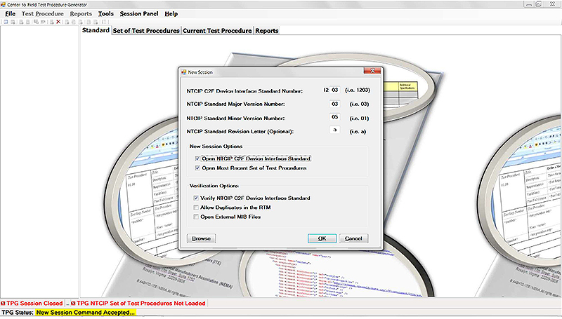
(Extended Text Description: Author's relevant description: This slide has a screen shot of the Test Procedure Generator application with the "New Session" window open. The window allows the user to indicate what NTCIP C2F Device Interface Standard Number (12xx), Major Version Number, Minor Version Number, and Revision Letter (Optional) are the test procedures being generated for. Two checkboxes are available under "New Session Options", Open NTCIP C2F Device Interface Standard and Open Most Recent Set of Test Procedures. There are three checkboxes available under "Verification Options", Verify NTCIP C2F Device Interface Standard, Allow Duplicates in the RTM, and Open External MIB Files. Three buttons are available in the window: Browse, OK, and Cancel.)
Slide 70:
How to Use the Test Procedure Generator Tool
Creating a New Set of Test Procedures

(Extended Text Description: Author's relevant description: This slide has a screen shot of the Test Procedure Generator's File menu with the drop-down option "New Set of Test Procedures" selected with the computer mouse. Other drop-down options are Display Requirement Text, Display Dialog Text, Close Session, Open Set of Test Procedures and Exit TPG. The following drop-down options are also shown but not selectable in this window (i.e., not highlighted) are New Session, Save Set of Test Procedures, Save XML Set of Test Procedures, and Delete Set of Test Procedures.)
Slide 71:
How to Use the Test Procedure Generator Tool
Creating a New Test Procedure

(Extended Text Description: Author's relevant description: This slide has a screen shot of the Test Procedure Generator's Test Procedures menu with the drop-down option "New Test Procedures" selected with the computer mouse. Drop-down options shown but not selectable in this window (i.e., not highlighted) are Edit Test Procedure, Delete Test Procedure, Save Test Procedure, Close Test Procedure, Modify Test Procedure ID, Define Test Procedure Header, Select Requirements, Define Variables, Test Procedure Step, Edit Test Procedure Step, Renumber Test Procedure Steps, and Re-sort Test Procedure Steps.)
Slide 72:
How to Use the Test Procedure Generator Tool
Creating a New Test Procedure

(Extended Text Description: Author's relevant description: This slide is a screen shot of the Test Procedure Generator. Two panes are shown - the left pane is a (selectable) list of all the requirements in NTCIP 1203 v03-01b in red while the right pane is a table template, in Microsoft Word, for a test case specification with cells for Test Procedure number, Description, Requirement(s), Variable(s), and Pass/Fail Criteria. On the screen is a portion of the test procedure:
| Test Procedure: 01.00 | Select the Test Procedure->Define Header Menu Item to enter the Test Procedure Title |
| Description: | Select the Test Procedure->Define Header Menu Item to enter the Test Procedure Description |
| Requirement(s): | Select the Test Procedure->Select Requirements Menu Item to enter the Test Procedure Requirements |
| Variable(s): | Select the Test Procedure->Define Variables menu item to enter the Test Procedure Variables |
| Pass/Fail Criteria: | Select the Test Procedure->Define Header Menu Item to enter the Test Procedure Pass/Fail Criteria |
)
Slide 73:
How to Use the Test Procedure Generator Tool
Creating a New Test Procedure
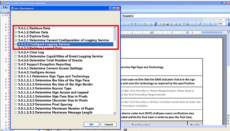
(Extended Text Description: Author's relevant description: This slide is a screen shot of the Test Procedure Generator with the snapshot from Slide #72 in the background. In the foreground is a window containing a list of the requirements id and title in the standard. This window allows the user to select, via checkboxes in front of each requirement, to be tested as part of a specific test procedure. There are two buttons in the window, OK and Cancel. The red box highlights the following menu options:
3.4.1.1 Retrieve Data
3.4.1.2 Deliver Data
3.4.1.3 Explore Data
3.4.2.1 Determine Current Configuration of Logging Service
3.4.2.2 Configure Logging Service)
Slide 74:
How to Use the Test Procedure Generator Tool
Creating a New Test Procedure
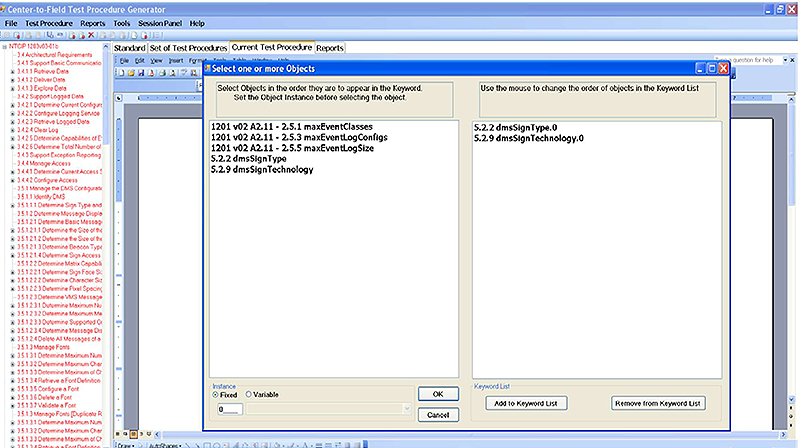
(Extended Text Description: Author's relevant description: This slide is a screen shot of the Test Procedure Generator with the snapshot from Slide #72 in the background. In the foreground is a window with two panes. The left pane contains a list of the data objects that trace to the earlier selected requirements (in Slide #73). The right pane contains a list of data objects that have been selected and will be added to a test procedure step. There are two buttons on the left pane, OK and Cancel. There are two buttons for the right pane, Add to Keyword List and Remove from Keyword List.)
Slide 75:
How to Use the Test Procedure Generator Tool
Creating a New Test Procedure
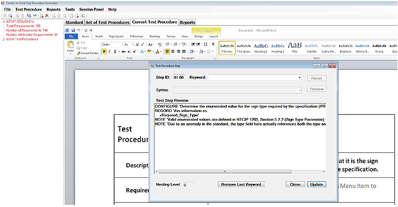
(Extended Text Description: Author's relevant description: This slide is a screen shot of the Test Procedure Generator. In the background are two panes. The left pane contains a tree structure in red with a list of test procedures for the NTCIP standard. The right pane contains a test procedure specification header. In the foreground is a window with the following fields: Step ID:, Keyword, Syntax, and Test Step Preview. For Step ID is the value 01.00, and in the Test Step Preview was the text, "CONFIGURE: Determine the enumerated value for the sign type required by the specification (PRL). RECORD this information as >>Required_Sign_Type. NOTE: Valid enumerated values are defined in NTCIP 1203, Section 5.2.2 (Sign Type Parameter). NOTE: Due to an anomaly in the standard, the type field here actually references both the type and..." There are three buttons in the window, Remove Last Keyword, Close, and Update.)
Slide 76:
How to Use the Test Procedure Generator Tool
Opening Test Procedures

(Extended Text Description: Author's relevant description: This slide is a screen shot of the Test Procedure Generator. Two panes are shown - the left pane is a (selectable) list of all the requirements in NTCIP 1203 v03-01b in red while the right pane is the cover of the NTCIP 1203 v03 standard, in Microsoft Word. The Test Procedure Generator's File menu is shown with the drop-down option "Open Set of Test Procedures" selected with the computer mouse. Other drop-down options are Display Requirement Text, Display Dialog Text, Close Session, New Set of Test Procedures and Exit TPG. The following drop-down options are also shown but not selectable in this window (i.e., not highlighted) are New Session, Save Set of Test Procedures, Save XML Set of Test Procedures, and Delete Set of Test Procedures.)
Slide 77:

Slide 78:
Question
What is the Requirements to Test Case Traceability Matrix (RTCTM) in a Test Design Specification based upon?
Answer Choices
- Includes all the requirements supported by the standard
- Includes only the requirements selected in the PRL that the Test Design Specification is based upon
- Includes only those requirements that are mandatory to conform to the standard
- Includes all the requirements that are contained in the project specifications
Slide 79:
Review of Answers
 a) Includes all the requirements supported by the standard
Incorrect. The RTCTM should list only those requirements specified in the TDS.
 b) Includes only the requirements selected in the PRL that the TDS is based upon
Correct! The RTCTM is based on the requirements selected.
 c) Includes only those requirements that are mandatory to conform to the standard
Incorrect. The RTCTM includes selected optional requirements.
 d) Includes all the requirements that are contained in the project specifications
Incorrect. Could be correct, but the PRL is complete, accurate and contains only the applicable requirements.
Slide 80:
Module Summary
- Describe within the context of a testing lifecycle the role of a test plan and the testing to be undertaken for DMS
- Identify the key elements of NTCIP 1203 v03 relevant to the test plan
- Describe the application of a good test plan to a DMS system being procured
- Describe a process of adapting a test plan based on the selected user needs and requirements
Slide 81:
We Have Now Completed the DMS Curriculum
 Module A311a:
Understanding User Needs for DMS Systems based on NTCIP 1203 Standard v03
 Module A311b:
Specifying Requirements for DMS Systems based on NTCIP 1203 Standard v03
 Module T311:
Applying Your Test Plan to Dynamic Message Signs based on NTCIP 1203 DMS Standard v03
Slide 82:
Thank you for completing this module.
Feedback
Please use the Feedback link below to provide us with your thoughts and comments about the value of the training.
Thank you!