Module 23 - A312b
A312b: Specifying Requirements for Transportation Sensor Systems (TSS) Based on NTCIP 1209 Standard
HTML of the PowerPoint Presentation
(Note: This document has been converted from a PowerPoint presentation to 508-compliant HTML. The formatting has been adjusted for 508 compliance, but all the original text content is included, plus additional text descriptions for the images, photos and/or diagrams have been provided below.)
Slide 1:

(Extended Text Description: Slide 1: Welcome - Graphic image of introductory slide. A large dark blue rectangle with a wide, light grid pattern at the top half and bands of dark and lighter blue bands below. There is a white square ITS logo box with words “Standards ITS Training” in green and blue on the middle left side. The word “Welcome” in white is to the right of the logo. Under the logo box are the words “RITA Intelligent Transportation Systems Joint Program Office.”)
Slide 2:
Welcome

Ken Leonard, Director
ITS Joint Program Office
(Extended Text Description: Intro Slide: Screen capture snapshot of RITA website - for illustration only. Below this image is a link to the current website: https://www.its.dot.gov/pcb - this screen capture snapshot shows an example from the RITA website from April 2013. At the top of the page it shows the RITA logo with the text U.S. Department of Transportation Research and Innovative Technology Administration - Intelligent Transportation Systems Joint Program Office - ITS Professional Capacity Building Program/Advanced ITS Education. Below the main site banner, it shows the main navigation menu with the following items: About, ITS Training, Knowledge Exchange, Technology Transfer, ITS in Academics, and Media Library. Below the main navigation menu, the page shows various content of the website, including a graphic image of professionals seated in a room during a training program. A text overlay has the text Welcome to ITS Professional Capacity Building. Additional content on the page includes a box entitled What's New and sections entitled Available E-Training (free), Free ITS Training and T3 Webinars. Again, this image serves for illustration only. The current website link is: https://www.its.dot.gov/pcb)
(Note: There is additional text attached to this slide that includes the following introductory information from Ken Leonard):
"ITS Standards can make your life easier. Your procurements will go more smoothly and you’ll encourage competition, but only if you know how to write them into your specifications and test them. This module is one in a series that covers practical applications for acquiring and testing standards-based ITS systems.
I am Ken Leonard, director of the ITS Joint Program Office for USDOT and I want to welcome you to our newly redesigned ITS standards training program of which this module is a part. We are pleased to be working with our partner, the Institute of Transportation Engineers, to deliver this new approach to training that combines web based modules with instructor interaction to bring the latest in ITS learning to busy professionals like yourself.
This combined approach allows interested professionals to schedule training at your convenience, without the need to travel. After you complete this training, we hope that you will tell colleagues and customers about the latest ITS standards and encourage them to take advantage of the archived version of the webinars.
ITS Standards training is one of the first offerings of our updated Professional Capacity Training Program. Through the PCB program we prepare professionals to adopt proven and emerging ITS technologies that will make surface transportation safer, smarter and greener which improves livability for us all. You can find information on additional modules and training programs on our web site ITS PCB Home
Please help us make even more improvements to our training modules through the evaluation process. We look forward to hearing your comments. Thank you again for participating and we hope you find this module helpful."
Slide 3:

Slide 4:
A312b:
Specifying Requirements for Transportation Sensor Systems (TSS) Based on NTCIP 1209 Standard
Slide 5:
Instructor

Ralph W. Boaz
President
Pillar Consulting, Inc. San Diego, CA, USA
Slide 6:
Target Audience
- Traffic engineering staff
- Traffic Management Center (TMC)/Operations staff
- System developers
- Private and public sector users including manufacturers
Slide 7:
Recommended Prerequisite(s)
- I101: Using ITS Standards: An Overview
- A101: Introduction to Acquiring Standards-based ITS Systems
- A102: Introduction to User Needs Identification
- A201: Details On Acquiring Standards-based ITS Systems
- C101: Introduction to the Communications Protocols and Their Uses in ITS Applications
- A312a: Understanding User Needs for Transportation Sensor Systems (TSS) Based on NTCIP 1209 Standard
Slide 8:
Curriculum Path (SEP)

(Extended Text Description: A graphical illustration indicating the sequence of training modules that lead up to this course. Each module is represented by a box with the name of the module in it and an arrow showing the logical flow of the modules and the preceding module and current module highlighted. There are 8 boxes in total; two rows of 3 boxes and a row of 2 boxes. The first box is labeled “I101 Using ITS Standards: An Overview.” An arrow from this box connects it to a box labeled “A101 Introduction to Acquiring Standards-based ITS Systems.” An arrow from this box connects it to a box labeled “A102 Introduction to User Needs Identification.” An arrow from this box connects it to a box located at the start of the next row labeled “A201 Details on Acquiring Standards-based ITS Systems.” An arrow from this box connects it to a box labeled “C101 Intro. To Comm. Protocols and Their Use in ITS Applications.” An arrow from this box connects it to a box labeled “C201 Introduction to the SNMP and its Applications in the NTCIP Standards.” An arrow from this box connects it to a box located at the start of the next row labeled “A312a Understanding User Needs for Transportation Sensor System Based on NTCIP 1209 Standard.” It is highlighted indicating that it is the direct predecessor to the current course. An arrow from this box connects to a box labeled “A312b Specifying Requirements for Transportation Sensor Systems (TSS) Based on NTCIP 1209 Standard.” It is highlighted indicating that it is the current course.)
Slide 9:
Learning Objectives
- Describe requirements included in the NTCIP 1209 v02 Standard
- Use the Protocol Requirements List (PRL) to specify an NTCIP TSS interface
- Achieve interoperability and interchangeability using the Requirements Traceability Matrix (RTM)
- Incorporate requirements not covered by the standard
- Explain the NTCIP 1209 v02 SNMP interface and dialogs
Slide 10:
Learning Objective #1 - Describe requirements included in the NTCIP 1209 v02 Standard
- Review components and structure of the NTCIP 1209 v02 Standard
- Use the PRL to trace the user needs to requirements
- Organization and decomposition of requirements of the NTCIP 1209 v02 Standard
Slide 11:
Learning Objective #1
Definition of a TSS within NTCIP 1209
A Transportation Sensor System (TSS) is defined as any system or device capable of sensing and communicating near real-time traffic parameters using NTCIP.
Slide 12:
Learning Objective #1
NTCIP 1209 Detection Architecture

(Extended Text Description: This slide, entitled “NTCIP 1209 Detection Architecture,” contains a graphic illustrating the detection architecture defined by the NTCIP 1209 Standard. The slide is composed of four graphic images. There is a computer terminal located in the middle left area of the slide. The computer terminal has a label above the graphic with the words “Management Station.” To the right of the computer terminal are three graphic images arranged vertically down the center of the slide. The top most graphic is one of a traffic controller connected to detectors as described in Slide 44. There is a label above this graphic with the words “Traffic Controllers.” The graphic beneath the traffic controller is a video detection camera which is shown as a cylindrical device with a camera lens at one end. The camera has a label above the graphic with the word “Video.” The graphic beneath the video detection camera is a rectangle containing the words “Radar, Magnetometer, Acoustic, Etc.” The rectangle has a label above the graphic with the words “Other Technologies.” There are solid lines connecting the computer terminal to the other three graphics. There is a legend at the bottom left of the slide indicating that the solid lines identify “NTCIP TSS Communications.”)
Graphics: Ralph W. Boaz
Slide 13:
Learning Objective #1
History of NTCIP 1209
-
NTCIP 1209 v01
- Oriented towards inductive loop technology
- Did not contain Systems Engineering Process (SEP) information
-
NTCIP 1209 v02
- Added SEP information
- Organized towards features
- Options for selecting requirements for specific technologies (inductive loop and machine vision)
- Structure conducive for including additional specific technology requirements in the future
Slide 14:
Learning Objective #1
Structure of the NTCIP 1209 v02 Standard
- General
- TSS Concept of Operations
- TSS Functional Requirements (includes Protocol Requirements List)
- TSS Dialogs
- Management Information Base (MIB)
Slide 15:
Learning Objective #1
Structure of the NTCIP 1209 v02 Standard (cont.)
Annex A Requirements Traceability Matrix (RTM)
Annex B Object Tree
Annex C Test Procedures (placeholder for the future)
Annex D Document Revisions
Slide 16:

Slide 17:
Learning Objective #1
What tool is used to show the relationship between requirements and dialogs within the standard?
Answer Choices
- Object Tree
- Protocol Requirements List (PRL)
- Requirements Traceability Matrix (RTM)
- Dialogs
Slide 18:
Learning Objective #1
Review of answers
 a) Object Tree
Incorrect. The Object Tree shows the hierarchical organization of the objects in the MIB.
 b) Protocol Requirements List (PRL)
Incorrect. The PRL shows the relationship of user needs to requirements.
 c) Requirements Traceability Matrix (RTM)
Correct. The RTM shows requirements traced to the interface items (dialogs and objects).
 d) Dialogs
Incorrect. Dialogs show the exchange of messages.
Slide 19:
Learning Objective #1
Use the PRL to Trace User Needs to Requirements
User Need Section Number |
User Need |
FR Section Number |
Functional Requirement |
Conformance |
Support / Project Requirement |
Additional Specifications |
|---|---|---|---|---|---|---|
2.5.1.7 |
Configure Outputs |
M |
Yes |
|||
3.4.1.6.1 |
Get Output Sensor Zone |
M |
Yes |
|||
3.4.1.6.2 |
Get Output Failsafe Mode |
M |
Yes |
|||
3.4.1.6.3 |
Get Output Mode Status |
M |
Yes |
|||
3.4.1.6.4 |
Get Output Label |
O |
Yes / No |
|||
... |
... |
... |
... |
|||
Slide 20:
Learning Objective #1
Use the PRL to Trace User Needs to Requirements
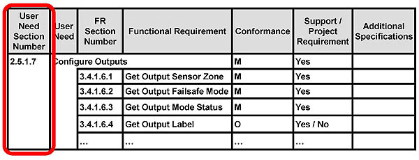
(Extended Text Description: This slide, entitled “Use the PRL to Trace User Needs to Requirements,” contains the PRL table from Slide 19 (repeated below) and is used to highlight the composition of the Protocol Requirements List. There is a rounded rectangle surrounding the column “User Need Section Number.”
User Need Section Number |
User Need |
FR Section Number |
Functional Requirement |
Conformance |
Support / Project Requirement |
Additional Specifications |
|---|---|---|---|---|---|---|
2.5.1.7 |
Configure Outputs |
M |
Yes |
|||
3.4.1.6.1 |
Get Output Sensor Zone |
M |
Yes |
|||
3.4.1.6.2 |
Get Output Failsafe Mode |
M |
Yes |
|||
3.4.1.6.3 |
Get Output Mode Status |
M |
Yes |
|||
3.4.1.6.4 |
Get Output Label |
O |
Yes / No |
|||
... |
... |
... |
... |
|||
)
Slide 21:
Learning Objective #1
Use the PRL to Trace User Needs to Requirements

(Extended Text Description: This slide, entitled “Use the PRL to Trace User Needs to Requirements,” contains the PRL table from Slide 19 (repeated below) and is used to highlight the composition of the Protocol Requirements List. There is a rounded rectangle surrounding the column “User Need.”
User Need Section Number |
User Need |
FR Section Number |
Functional Requirement |
Conformance |
Support / Project Requirement |
Additional Specifications |
|---|---|---|---|---|---|---|
2.5.1.7 |
Configure Outputs |
M |
Yes |
|||
3.4.1.6.1 |
Get Output Sensor Zone |
M |
Yes |
|||
3.4.1.6.2 |
Get Output Failsafe Mode |
M |
Yes |
|||
3.4.1.6.3 |
Get Output Mode Status |
M |
Yes |
|||
3.4.1.6.4 |
Get Output Label |
O |
Yes / No |
|||
... |
... |
... |
... |
|||
)
Slide 22:
Learning Objective #1
User Need - Configure Outputs
2.5.1.7 Configure Outputs
This feature allows the management station to configure the outputs to report the state of zones (e.g., assigning an output to a zone, conditioning of outputs to include delay and extension, assigning fail-safe/fail-secure mode of operation, force output on/off).
Slide 23:
Learning Objective #1
Use the PRL to Trace User Needs to Requirements
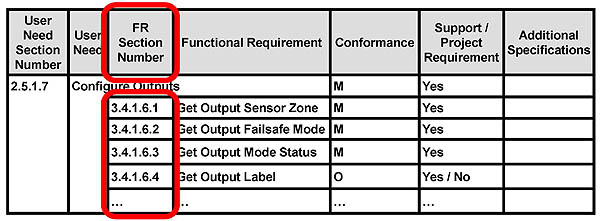
(Extended Text Description: This slide, entitled “Use the PRL to Trace User Needs to Requirements,” contains the PRL table from Slide 19 (repeated below) and is used to highlight the composition of the Protocol Requirements List. There is a rounded rectangle surrounding the column “FR Section Number.”
User Need Section Number |
User Need |
FR Section Number |
Functional Requirement |
Conformance |
Support / Project Requirement |
Additional Specifications |
|---|---|---|---|---|---|---|
2.5.1.7 |
Configure Outputs |
M |
Yes |
|||
3.4.1.6.1 |
Get Output Sensor Zone |
M |
Yes |
|||
3.4.1.6.2 |
Get Output Failsafe Mode |
M |
Yes |
|||
3.4.1.6.3 |
Get Output Mode Status |
M |
Yes |
|||
3.4.1.6.4 |
Get Output Label |
O |
Yes / No |
|||
... |
... |
... |
... |
|||
)
Slide 24:
Learning Objective #1
Use the PRL to Trace User Needs to Requirements
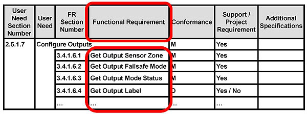
(Extended Text Description: This slide, entitled “Use the PRL to Trace User Needs to Requirements,” contains the PRL table from Slide 19 (repeated below) and is used to highlight the composition of the Protocol Requirements List. There is a rounded rectangle surrounding the column “Functional Requirement.”
User Need Section Number |
User Need |
FR Section Number |
Functional Requirement |
Conformance |
Support / Project Requirement |
Additional Specifications |
|---|---|---|---|---|---|---|
2.5.1.7 |
Configure Outputs |
M |
Yes |
|||
3.4.1.6.1 |
Get Output Sensor Zone |
M |
Yes |
|||
3.4.1.6.2 |
Get Output Failsafe Mode |
M |
Yes |
|||
3.4.1.6.3 |
Get Output Mode Status |
M |
Yes |
|||
3.4.1.6.4 |
Get Output Label |
O |
Yes / No |
|||
... |
... |
... |
... |
|||
)
Slide 25:
Learning Objective #1
Requirements for User Need Configure Outputs
3.4.1.6.1 Get Output Sensor Zone
The TSS shall allow a management station to determine the sensor zone assigned to an output.
3.4.1.6.2 Get Output Failsafe Mode
The TSS shall allow a management station to determine the last fail-safe mode command.
Slide 26:
Learning Objective #1
Requirements for User Need Configure Outputs
3.4.1.6.3 Get Output Mode Status
The TSS shall allow a management station to determine the current output mode status of an output.
3.4.1.6.4 Get Output Label
The TSS shall allow a management station to determine the label assigned to an output.
Slide 27:
Learning Objective #1
Use the PRL to Trace User Needs to Requirements
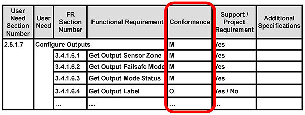
(Extended Text Description: This slide, entitled “Use the PRL to Trace User Needs to Requirements,” contains the PRL table from Slide 19 (repeated below) and is used to highlight the composition of the Protocol Requirements List. There is a rounded rectangle surrounding the column “Conformance.”
User Need Section Number |
User Need |
FR Section Number |
Functional Requirement |
Conformance |
Support / Project Requirement |
Additional Specifications |
|---|---|---|---|---|---|---|
2.5.1.7 |
Configure Outputs |
M |
Yes |
|||
3.4.1.6.1 |
Get Output Sensor Zone |
M |
Yes |
|||
3.4.1.6.2 |
Get Output Failsafe Mode |
M |
Yes |
|||
3.4.1.6.3 |
Get Output Mode Status |
M |
Yes |
|||
3.4.1.6.4 |
Get Output Label |
O |
Yes / No |
|||
... |
... |
... |
... |
|||
)
Slide 28:
Learning Objective #1
Use the PRL to Trace User Needs to Requirements

(Extended Text Description: This slide, entitled “Use the PRL to Trace User Needs to Requirements,” contains the PRL table from Slide 19 (repeated below) and is used to highlight the composition of the Protocol Requirements List. There is a rounded rectangle surrounding the column “Support/Project Requirement.”
User Need Section Number |
User Need |
FR Section Number |
Functional Requirement |
Conformance |
Support / Project Requirement |
Additional Specifications |
|---|---|---|---|---|---|---|
2.5.1.7 |
Configure Outputs |
M |
Yes |
|||
3.4.1.6.1 |
Get Output Sensor Zone |
M |
Yes |
|||
3.4.1.6.2 |
Get Output Failsafe Mode |
M |
Yes |
|||
3.4.1.6.3 |
Get Output Mode Status |
M |
Yes |
|||
3.4.1.6.4 |
Get Output Label |
O |
Yes / No |
|||
... |
... |
... |
... |
|||
)
Slide 29:
Learning Objective #1
Use the PRL to Trace User Needs to Requirements
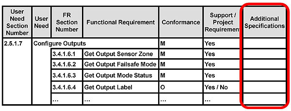
(Extended Text Description: This slide, entitled “Use the PRL to Trace User Needs to Requirements,” contains the PRL table from Slide 19 (repeated below) and is used to highlight the composition of the Protocol Requirements List. There is a rounded rectangle surrounding the column “Additional Specifications.”
User Need Section Number |
User Need |
FR Section Number |
Functional Requirement |
Conformance |
Support / Project Requirement |
Additional Specifications |
|---|---|---|---|---|---|---|
2.5.1.7 |
Configure Outputs |
M |
Yes |
|||
3.4.1.6.1 |
Get Output Sensor Zone |
M |
Yes |
|||
3.4.1.6.2 |
Get Output Failsafe Mode |
M |
Yes |
|||
3.4.1.6.3 |
Get Output Mode Status |
M |
Yes |
|||
3.4.1.6.4 |
Get Output Label |
O |
Yes / No |
|||
... |
... |
... |
... |
|||
)
Slide 30:
Learning Objective #1
Organization of Requirements
3.4.1 Manage the TSS Configuration
3.4.2 Monitor the Current Status
3.4.3 Collection of Sample Data 3.5 Multi-Version Interoperability
Slide 31:
Learning Objective #1
TSS Requirements Are "Well-Formed"
[Actor] [Action] [Target] [Constraint] [Localization]
Actor Identifies who or what that does the action
Action Identifies what is to happen
Target Identifies who or what receives the action
Constraint Identifies how to measure success or failure of the requirement
Localization Identifies the circumstances under which the requirement applies
Localization and constraint portions are important but not all requirements will have both
Slide 32:
Learning Objective #1
Example TSS Requirement
[Actor] [Action] [Target] [Constraint] [Localization]

(Extended Text Description: This slide, entitled “Example TSS Requirement,” provides an example TSS requirement. As the instructor speaks, four ovals appear encompassing various parts of the requirement that are part of the structure of a well formed requirement. The ovals are identified by uppercase text using arrows. “The TSS” is encompassed and pointed to by “ACTOR.” “to determine” is encompassed and pointed to by “ACTION.” “the label” is encompassed and pointed to by “TARGET.” “assigned to an output” is encompassed and pointed to by “LOCALIZATION.”)
Slide 33:
Learning Objective #1
3.4.1 Manage the TSS Configuration
3.4.1.1 Identify the TSS (7 reqs)
3.4.1.2 Determine the TSS Capabilities (10 reqs)
3.4.1.3 Control the TSS (14 reqs)
3.4.1.4 Manage Real-Time Clock (RTC) (4 reqs)
3.4.1.5 Manage Sensor Zones (57 reqs)
3.4.1.6 Manage Outputs (11 reqs)
3.4.1.7 Manage Camera (19 reqs)
Slide 34:
Learning Objective #1
3.4.2 Monitor the Current Status of the TSS
3.4.2.1 Get System Status (1 req)
3.4.2.2 TSS Sensor Status (11 reqs)
3.4.2.3 Monitor Output States (1 req)
Slide 35:
Learning Objective #1
3.4.3 Collection of Sample Data
3.4.3.1 Retrieve Historical Sample Data from the TSS (6 reqs)
3.4.3.2 Get Zone Class Label (1 req)
3.4.3.3 Get Number of Sample Data Entries (1 req)
3.4.3.4 Get Number of Sensor Zone Classes (1 req)
Slide 36:
Learning Objective #1
3.5 Multi-Version Interoperability (MVI -Backward Compatibility)
3.5.1 Retrieve Most Recent NTCIP 1209:2005 (v01) Conformant Data Sample Table (5 reqs)
3.5.2 Retrieve NTCIP 1209:2005 (v01) Conformant Historical Sample Data Table (5 reqs)
3.5.3 Loop Output Conditioning Table (12 reqs)
Slide 37:

Slide 38:
Learning Objective #1
Which of the following is not a major group of requirements in NTCIP 1209 v02?
Answer Choices
- Manage the TSS configuration
- Manage the camera
- Collect sample data
- Multi-version interoperability (backward compatibility)
Slide 39:
Learning Objective #1
Review of answers
 a) Manage the TSS configuration
Incorrect. This major group of requirements covers Configuration and Control requirements of the TSS.
 b) Manage the camera
Correct. Manage the camera is included in manage the TSS configuration so it is not its own major group. Monitor the TSS is the remaining major group.
 c) Collect sample data
Incorrect. This major group of requirements refers to the collection of near real-time data.
 d) Multi-version interoperability (backward compatibility)
Incorrect. This major group of requirements refers to the design of the standard in version NTCIP 1209 v01.
Slide 40:
Summary of Learning Objective #1
Describe requirements included in the NTCIP 1209 v02 Standard
- Review components and structure of the NTCIP 1209 v02 Standard
- Use the PRL to trace the user needs to requirements
- Organization and decomposition of requirements of the NTCIP 1209 v02 Standard
Slide 41:
Learning Objective #2 - Use the Protocol Requirements List (PRL) to specify an NTCIP TSS interface
- Specify performance criteria for functional requirements within the PRL
- Specify limits or ranges for functional requirements within the PRL
- Use Optional Requirements and Predicates within the PRL
- Use the PRL in a Specification
Slide 42:
Learning Objective #2
Specifying Performance Criteria for Functional Requirements
User Need Section Number |
User Need |
FR Section Number |
Functional Requirement |
Conformance |
Support / Project Requirement |
Additional Specifications |
|---|---|---|---|---|---|---|
2.5.4.1 |
Retrieve In-Progress Sample Data |
Sample:M Speed:M |
Yes / N/A |
|||
3.4.3.1.1 |
Get Historical Sample End Time |
Sample:M |
Yes / N/A |
|||
3.4.3.1.2 |
Get Historical Sample Volume |
Sample:M |
Yes / N/A |
|||
3.4.3.1.3 |
Get Historical Sample Percent Occupancy |
Sample:M |
Yes / N/A |
|||
... |
... |
... |
... |
|||
Slide 43:
Learning Objective #2
Specifying Performance Criteria for Functional Requirements
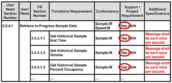
(Extended Text Description: This slide, entitled “Specifying Performance Criteria for Functional Requirements,” contains a PRL table with all of the “Yes” options in the Support/Project Requirement column encompassed by ovals:
User Need Section Number |
User Need |
FR Section Number |
Functional Requirement |
Conformance |
Support / Project Requirement |
Additional Specifications |
|---|---|---|---|---|---|---|
2.5.4.1 |
Retrieve In-Progress Sample Data |
Sample:M Speed:M |
Yes / N/A |
|||
3.4.3.1.1 |
Get Historical Sample End Time |
Sample:M |
Yes / N/A |
Message shall be sent once per second. |
||
3.4.3.1.2 |
Get Historical Sample Volume |
Sample:M |
Yes / N/A |
Message shall be sent once per second. |
||
3.4.3.1.3 |
Get Historical Sample Percent Occupancy |
Sample:M |
Yes / N/A |
Message shall be sent once per second. |
||
... |
... |
... |
... |
|||
)
Slide 44:
Learning Objective #2
Specifying Limits or Ranges on Requirements

(Extended Text Description: This slide, entitled “Specifying Limits or Ranges on Requirements,” contains a PRL table with all of the “Yes” options in the Support/Project Requirement column encompassed by ovals:
User Need Section Number |
User Need |
FR Section Number |
Functional Requirement |
Conformance |
Support / Project Requirement |
Additional Specifications |
|---|---|---|---|---|---|---|
2.5.1.2 |
Determine TSS Capabilities |
M |
Yes |
|||
3.4.1.2.1 |
Determine Maximum Number of Sensor Zones |
M |
Yes |
|||
3.4.1.2.2 |
Determine Maximum Number of Historical Data Entries per Sensor Zones |
Sample:M |
Yes / N/A |
Max number of Historical Data Entries shall be 4. |
||
3.4.1.2.3 |
Determine Maximum Number of Outputs |
M |
Yes |
|||
... |
... |
... |
... |
|||
)
Slide 45:
Learning Objective #2
Using Optional Requirements and Predicates
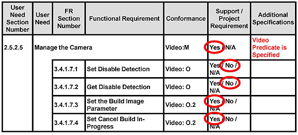
(Extended Text Description: This slide, entitled “Using Optional Requirements and Predicates,” contains a PRL table with one of the “Yes / No / N/A” options in the Support/Project Requirement column encompassed by ovals as follows: Row 1 – “Yes” Row 2 – “No” Row 3 – “No” Row 4 – “Yes” Row 5 – “Yes”:
User Need Section Number |
User Need |
FR Section Number |
Functional Requirement |
Conformance |
Support / Project Requirement |
Additional Specifications |
|---|---|---|---|---|---|---|
2.5.2.5 |
Manage the Camera |
Video:M |
Yes / N/A |
Video Predicate is Specified |
||
3.4.1.7.1 |
Set Disable Detection |
Video: O |
Yes / No / N/A |
|||
3.4.1.7.2 |
Get Disable Detection |
Video: O |
Yes / No / N/A |
|||
3.4.1.7.3 |
Set the Build Image Parameter |
Video: O.2 |
Yes / No / N/A |
|||
3.4.1.7.4 |
Set Cancel Build In-Progress |
Video: O.2 |
Yes / No / N/A |
|||
)
Slide 46:
Learning Objective #2
Using the PRL in a Specification
- Shows relationship of user needs (features) to requirements
- Primary tool for specifying the NTCIP 1209 interface
- Completed PRL always included in NTCIP 1209 specification
Slide 47:
Learning Objective #2
Review of the Predicates Used in NTCIP 1209 v02
- Loop (Inductive Loop)
- Video (Machine Vision)
- RTC (Real-Time Clock)
- Speed
- Timing
- Sample
- Version1
Slide 48:
Learning Objective #2
Review of Conformance Status Used in NTCIP 1209 v02
Symbol |
Conformance Status |
|---|---|
M |
Mandatory |
O |
Optional |
O.# |
Part of an "Option Group" where "#" indicates the group number (e.g., "O.2" means Option Group 2). If a requirement associated with a particular Option Group is to be supported, then all requirements in the standard that are associated with that Option Group must also be supported. |
N/A |
Not applicable (i.e., logically impossible in the scope of the standard) |
Slide 49:
Learning Objective #2
Process for Using the PRL in NTCIP 1209 v02
- Make a copy of the PRL table
- Determine which predicates apply to your specification of the NTCIP 1209 v02
-
Step through each User Need in the PRL and indicate whether it is to be included
- Circle Yes for all User Needs indicated by an M
- Circle Yes or No for all User Needs indicated by an O
Slide 50:
Learning Objective #2
Process for Using the PRL in NTCIP 1209 v02 (cont.)
-
Step through each User Need in the PRL and indicate whether it is to be included (cont.)
- Circle Yes to all User Needs indicated by <Predicate>:M for the predicates determined in Step #2
- Circle Yes or No for all User Needs indicated by a <Predicate>:O and <Predicate>:O#
- Verify that all User Needs with a like <Predicate>:O# have a Yes circled
- Circle No or N/A as appropriate for all remaining User Needs
Slide 51:
Learning Objective #2
Process for Using the PRL in NTCIP 1209 v02 (cont.)
-
Step through each Requirement for each User Need in the PRL that has a circled Yes
- Circle Yes for all Requirements indicated by an M
- Circle Yes or No for all Requirements indicated by an O
- Circle Yes to all Requirements indicated by <Predicate>:M for the predicates determined in Step #2
- Circle Yes or No for all Requirements indicated by a <Predicate>:O and <Predicate>:O#
- Verify that all Requirements with a like <Predicate>:O# have a Yes circled
Slide 52:
Learning Objective #2
Process for Using the PRL in NTCIP 1209 v02 (cont.)
-
Step through each Requirement for each User Need in the PRL that has a circled Yes (cont.)
- Circle No or N/A as appropriate for all remaining Requirements
- Enter any limits or ranges to be applied to any of the included requirements in the PRL
- Enter any performance criteria for any of the included requirements in the PRL
- Enter any other special instructions for any requirement in the PRL
Slide 53:

Slide 54:
Learning Objective #2
If Video:O.2 is used in the conformance column of the TSS PRL, what does it mean?
Answer Choices
- It's the second of 20 optional Video requirements in the standard
- It identifies the second highest priority optional Video requirement
- Says that if one Video:O.2 optional requirement is used in the project, all Video:O.2 requirements must be used
- None of the above
Slide 55:
Learning Objective #2
Review of answers
 a) It's the second of 20 optional Video requirements in the standard
Incorrect. There is no numbering of requirements in the conformance column of the PRL.
 b) It identifies the second highest priority optional Video requirement
Incorrect. There is no priority of requirements indicated in the conformance column of the PRL.
 c) Says that if one Video:O.2 optional requirement is used in the project, all Video:O.2 requirements must be used
Correct This is the method used to identify an option group.
 d) None of the above
Incorrect. There is a correct answer listed above.
Slide 56:
Summary of Learning Objective #2
Use the Protocol Requirements List (PRL) to specify an NTCIP TSS interface
- Specify performance requirements within the PRL
- Specify limits or ranges on requirements within the PRL
- Use Optional Requirements and Predicates
- Use the PRL in a Specification
Slide 57:
Learning Objective #3 - Achieve interoperability and interchangeability using the Requirements Traceability Matrix (RTM)
- How the RTM traces to a single design
- How to determine that a management station and device will be interoperable
- How to determine that two devices will be interchangeable
Slide 58:
Learning Objective #3
How the RTM traces to a single design
- Shows relationship of requirements to the specific design items of the interface (dialogs and data objects)
- Used by system software and TSS manufacturers implementing the standard
- Useful for identifying data objects within standard that may be subranged within the specification
- RTM information presented in the standard does not need to be repeated in an agency specification
Slide 59:
Learning Objective #3
Using the Requirements Traceability Matrix
Requirement ID |
Requirement |
Dialog ID |
Dialog |
Object ID |
Object |
|---|---|---|---|---|---|
3.4.3.1.7 |
Get Zone Class Label |
||||
4.3.3.5 |
Retrieve Sensor Zone Class Labels |
||||
5.2.4 |
maxSensorZones |
||||
5.2.10 |
functionalCapabilities |
||||
5.4.5.1 |
zoneClassLabel |
||||
Slide 60:
Learning Objective #3
Using the Requirements Traceability Matrix
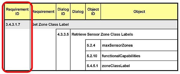
(Extended Text Description: This slide, entitled “Using the Requirements Traceability Matrix,” contains the RTM table from Slide 59 (repeated below) and is used to highlight the composition of the Requirements Traceability Matrix. There is a rounded rectangle surrounding the column “Requirement ID.”
Requirement ID |
Requirement |
Dialog ID |
Dialog |
Object ID |
Object |
|---|---|---|---|---|---|
3.4.3.1.7 |
Get Zone Class Label |
||||
4.3.3.5 |
Retrieve Sensor Zone Class Labels |
||||
5.2.4 |
maxSensorZones |
||||
5.2.10 |
functionalCapabilities |
||||
5.4.5.1 |
zoneClassLabel |
||||
)
Slide 61:
Learning Objective #3
Using the Requirements Traceability Matrix
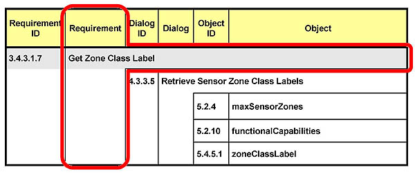
(Extended Text Description: This slide, entitled “Using the Requirements Traceability Matrix,” contains the RTM table from Slide 59 (repeated below) and is used to highlight the composition of the Requirements Traceability Matrix. There is a rounded rectangle surrounding the column “Requirement.”
Requirement ID |
Requirement |
Dialog ID |
Dialog |
Object ID |
Object |
|---|---|---|---|---|---|
3.4.3.1.7 |
Get Zone Class Label |
||||
4.3.3.5 |
Retrieve Sensor Zone Class Labels |
||||
5.2.4 |
maxSensorZones |
||||
5.2.10 |
functionalCapabilities |
||||
5.4.5.1 |
zoneClassLabel |
||||
)
Slide 62:
Learning Objective #3
Using the Requirements Traceability Matrix
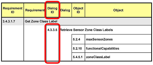
(Extended Text Description: This slide, entitled “Using the Requirements Traceability Matrix,” contains the RTM table from Slide 59 (repeated below) and is used to highlight the composition of the Requirements Traceability Matrix. There is a rounded rectangle surrounding the column “Dialog ID.”
Requirement ID |
Requirement |
Dialog ID |
Dialog |
Object ID |
Object |
|---|---|---|---|---|---|
3.4.3.1.7 |
Get Zone Class Label |
||||
4.3.3.5 |
Retrieve Sensor Zone Class Labels |
||||
5.2.4 |
maxSensorZones |
||||
5.2.10 |
functionalCapabilities |
||||
5.4.5.1 |
zoneClassLabel |
||||
)
Slide 63:
Learning Objective #3
Using the Requirements Traceability Matrix
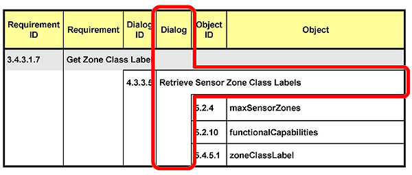
(Extended Text Description: This slide, entitled “Using the Requirements Traceability Matrix,” contains the RTM table from Slide 59 (repeated below) and is used to highlight the composition of the Requirements Traceability Matrix. There is a rounded rectangle surrounding the column “Dialog.”
Requirement ID |
Requirement |
Dialog ID |
Dialog |
Object ID |
Object |
|---|---|---|---|---|---|
3.4.3.1.7 |
Get Zone Class Label |
||||
4.3.3.5 |
Retrieve Sensor Zone Class Labels |
||||
5.2.4 |
maxSensorZones |
||||
5.2.10 |
functionalCapabilities |
||||
5.4.5.1 |
zoneClassLabel |
||||
)
Slide 64:
Learning Objective #3
Using the Requirements Traceability Matrix
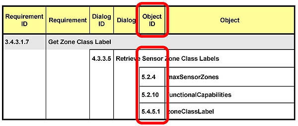
(Extended Text Description: This slide, entitled “Using the Requirements Traceability Matrix,” contains the RTM table from Slide 59 (repeated below) and is used to highlight the composition of the Requirements Traceability Matrix. There is a rounded rectangle surrounding the column “Object ID.”
Requirement ID |
Requirement |
Dialog ID |
Dialog |
Object ID |
Object |
|---|---|---|---|---|---|
3.4.3.1.7 |
Get Zone Class Label |
||||
4.3.3.5 |
Retrieve Sensor Zone Class Labels |
||||
5.2.4 |
maxSensorZones |
||||
5.2.10 |
functionalCapabilities |
||||
5.4.5.1 |
zoneClassLabel |
||||
)
Slide 65:
Learning Objective #3
Using the Requirements Traceability Matrix
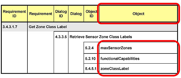
(Extended Text Description: This slide, entitled “Using the Requirements Traceability Matrix,” contains the RTM table from Slide 59 (repeated below) and is used to highlight the composition of the Requirements Traceability Matrix. There is a rounded rectangle surrounding the column “Object.”
Requirement ID |
Requirement |
Dialog ID |
Dialog |
Object ID |
Object |
|---|---|---|---|---|---|
3.4.3.1.7 |
Get Zone Class Label |
||||
4.3.3.5 |
Retrieve Sensor Zone Class Labels |
||||
5.2.4 |
maxSensorZones |
||||
5.2.10 |
functionalCapabilities |
||||
5.4.5.1 |
zoneClassLabel |
||||
)
Slide 66:
Learning Objective #3
How to determine that a management station and device will be interoperable
Interoperability
- Ability of two or more devices to exchange information
- Ability to use the information that has been exchanged
Slide 67:
Learning Objective #3
How to determine that a management station and device will be interoperable
- RTM provides for interoperability by defining a specific design to fulfill a communications requirement
- PRL indicates which requirements are supported
- Comparison of the PRLs for the management station and field device allows a quick determination of interoperability
Can the management station and field device fulfill each requirement in a cooperative way?
Slide 68:
Learning Objective #3
How to determine that two devices will be interchangeable
Interchangeability
- Same functional and physical characteristics so as to be equivalent in performance and durability (subjective)
- Ability to exchange devices of the same type without alteration to the device or adjoining items (adjustments permitted, subjective)
Slide 69:
Learning Objective #3
How to determine that two devices will be interchangeable
- Must be interoperable in same system
- Compatible on same communications channel
- Standard functions provide same results
- Subjective measures important to the agency (accuracy, maintenance, etc.)
Is it close enough for you?
Slide 70:
Learning Objective #3
Off-the-Shelf Interoperability and Interchangeability
- Systems using only standardized requirements, data objects and dialogs facilitates interoperability and makes interchangeability a possibility
- Systems using requirements, data objects and dialogs not in the standard make interoperability and interchangeability difficult
Slide 71:

Slide 72:
Learning Objective #3
Which statement is TRUE in regards to achieving interchangeability for TSS equipment using NTCIP 1209 v02?
Answer Choices
- Using user needs from the standard guarantees interchangeability
- Using only requirements, data elements and dialogs from the standard guarantees interchangeability
- Adding communications data elements that are not in the standard makes interchangeability impossible
- Using only requirements, data elements and dialogs from the standard makes interchangeability a possibility
Slide 73:
Learning Objective #3
Review of answers
 a) Using user needs from the standard guarantees interchangeability
Incorrect. User needs (features) identified in the standard are at a high level that, by themselves, are not explicit enough for interchangeability.
 b) Using only requirements, data elements, and dialogs from the standard guarantees interchangeability
Incorrect. Interchangeability may be affected by other aspects of the TSS device - not just communications.
 c) Adding communications data elements that are not in the standard makes interchangeability impossible
Incorrect. Using data elements not in the standard may limit choices of manufacturers willing or able to provide support for those data elements but interchangeability is not impossible technically.
 d) Using only requirements, data elements and dialogs from the standard makes interchangeability a possibility
Correct. Using only the standardized interface items provides the best opportunity for interchangeability.
Slide 74:
Learning Objective #3
Which statement is TRUE in regards to the RTM in NTCIP 1209 v02?
Answer Choices
- Shows relationship of requirements to the specific design items of the TSS interface
- Shows relationship of user needs to the specific design items of the TSS interface
- Should always be included in an agency specification
- Not used until integration of the system and the TSS device
Slide 75:
Learning Objective #3
Review of answers
 a) Shows relationship of requirements to the specific design items of the TSS interface
Correct. The design items include the data objects and dialogs.
 b) Shows relationship of user needs to the specific design items of the TSS interface
Incorrect. User needs are found in the Protocol Requirements List.
 c) Should always be included in an agency specification
Incorrect. RTM information is only needed in an agency specification if there is something different from the standard.
 d) Not used until integration of the system and the TSS device
Incorrect. The RTM is used by system software and TSS manufacturers implementing the standard.
Slide 76:
Summary of Learning Objective #3
Achieve interoperability and interchangeability using the Requirements Traceability Matrix (RTM)
- How the RTM traces to a single design
- How to determine that a management station and device will be interoperable
- How to determine that two devices will be interchangeable
Slide 77:
Learning Objective #4 - Incorporate requirements not covered by the standard
- Conditions and context for extending the NTCIP 1209 v02 Standard
- Example of Extending the NTCIP 1209 v02 Standard
Slide 78:
Learning Objective #4
Conditions and context for extending the NTCIP 1209 v02 Standard
-
Consider the warnings in the previous learning objective
- Using only standardized requirements, data objects and dialogs facilitates interoperability and interchangeability
- Using requirements, data objects and dialogs not in the standard make interoperability and interchangeability difficult
- If extending the standard, the extensions should be documented and made available to anyone
Slide 79:
Learning Objective #4
Conditions and context for extending the NTCIP 1209 v02 Standard (cont.)
-
Extending or adding to the TSS Standard can make sense to provide for:
- Control features and requirements that are specific to certain sensor technologies
- Data available in sensor technologies not yet covered in the standard
Slide 80:
Learning Objective #4
Sensor Technologies That May Have Technology-Specific Features
- Loop *
- Video *
- Microwave Radar
- Magnetometer
- Acoustic
- Ultrasonic
- Infrared
- Laser
- Piezoelectric
- Pneumatic
- Light-Sensitive
* - Technology-specific features included in NTCIP 1209 v02
Slide 81:
Learning Objective #4
Example of Extending the NTCIP 1209 v02 Standard
85th Percentile Speed
A speed at or below which 85 percent of people drive at any given location under good weather and visibility conditions may be considered as the maximum safe speed for that location.
Scenario:
We are an agency that wishes to include 85th Pecentile Speed in our TSS Specification
Slide 82:
Learning Objective #4
Example of Extending the NTCIP 1209 v02 Standard (cont.)
Assume our specification is arranged as follows -
- Sections 1-5 cover requirements and specifications identified for the majority of our TSS device
- Section 6 covers extensions to NTCIP 1209 v02
- Section 6.1 has some introductory information
- Section 6.2 identifies needs/features
- Section 6.3 states requirements
- Section 6.4 describes dialogs
- Section 6.5 provides object definitions
Slide 83:
Learning Objective #4
Example of Extending the NTCIP 1209 v02 Standard (cont.)
Need / Feature
6.2.1 85th Percentile Speed
This feature allows the management station to obtain the 85th percentile speed from the TSS.
Slide 84:
Learning Objective #4
Example of Extending the NTCIP 1209 v02 Standard (cont.)
Requirements
6.3.1 Get 85th Percentile Speed
The TSS shall allow a management station to retrieve the 85th percentile speed for each zone.
6.3.2 Reset 85th Percentile Speed
The TSS shall allow a management station to reset the 85th percentile speed.
Slide 85:
Learning Objective #4
Example of Extending the NTCIP 1209 v02 Standard (cont.)
PRL
User Need Section Number |
User Need |
FR Section Number |
Functional Requirement |
Conformance |
Support / Project Requirement |
Additional Specifications |
|---|---|---|---|---|---|---|
6.2.1 |
85th Percentile Speed |
M |
Yes |
|||
6.3.1 |
Get 85th Percentile Speed |
M |
Yes |
|||
6.3.2 |
Reset 85th Percentile Speed |
M |
Yes |
|||
Slide 86:
Learning Objective #4
Example of Extending the NTCIP 1209 v02 Standard (cont.)
RTM
Requirement ID |
Requirement |
Dialog ID |
Dialog |
Object ID |
Object |
|---|---|---|---|---|---|
6.3.1 |
Get 85th Percentile Speed |
||||
6.4.1 |
Retrieve 85th Percentile Speed |
||||
6.5.1 |
zoneEightyFifthPCTLSpeed |
||||
6.3.2 |
Reset 85th Percentile Speed |
||||
6.4.2 |
Initialize 85th Percentile Speed |
||||
6.5.2 |
resetZoneEightyFifthPCTLSpeed |
||||
Slide 87:
Learning Objective #4
Example of Extending the NTCIP 1209 v02 Standard (cont.)
zoneEightyFifthPCTLSpeed OBJECT-TYPE
SYNTAX INTEGER (1..2550)
ACCESS read-only
STATUS mandatory
DESCRIPTION
"<Definition> Indicates the
85th percentile speed for a zone.
<Unit> tenths of km/h
<Object Identifier> 1.3.6.1.4.1.1206.4.2.4.3.6.1.1"
::= { zoneSpeedDataEntry 1 }
Slide 88:

Slide 89:
Learning Objective #4
Which of the following is justification for extending the standard with a new feature?
Answer Choices
- When you are not worried about interoperability or interchangeability
- After you have weighed the risk of making interoperability and interchangeability more difficult against the benefit of the feature
- When you want to disqualify a second vendor because you have done business with another in the past
- When a proprietary method to accomplish a feature is more familiar over the method used in the standard
Slide 90:
Learning Objective #4
Review of answers
 a) When you are not worried about interoperability or interchangeability
Incorrect. If not concerned with interoperability or interchangeability, why use NTCIP at all?
 b) After you have weighed the risk of making interoperability and interchangeability more difficult against the benefit of the feature
Correct. It should be a significant enhancement.
 c) When you want to disqualify a second vendor because you have done business with another in the past
Incorrect. You may find yourself trapped into one vendor in the future even if they perform poorly.
 d) When a proprietary method to accomplish a feature is more familiar over the method used in the standard
Incorrect. If there is a standard method to accomplish the same feature, it is best to use it.
Slide 91:
Summary of Learning Objective #4
Incorporate Requirements Not Covered by the Standard
- Conditions and context for extending the NTCIP 1209 v02 Standard
- Example of Extending the NTCIP 1209 v02 Standard
Slide 92:
Learning Objective #5 - Explain the TSS SNMP Interface and Dialogs
- Example dialogs from NTCIP 1209 v02
- Example of a dialog extension to the standard
Slide 93:
Learning Objective #5
A Standard SNMP Get Dialog

(Extended Text Description: This slide, entitled “A Standard SNMP Get Dialog,” contains a graphic form of a dialog referred to as a sequence diagram. Items in the diagram are arranged on two vertical axes parallel to each other. On the left, from top to bottom, there is a stick man, a label saying “:Management Station,” and a slender (much taller than wide) rectangle extending down the left axis. On the right, from top to bottom, there is a box labeled “:TSS” and a slender (much taller than wide) rectangle extending down the right axis. At the top of the two slender rectangles there is a thin horizontal arrow extending from the left rectangle to the right rectangle. The arrow is labeled “Get(varBindingList).” Approximately, half the distance of the height of the rectangles, there is a thin horizontal arrow extending from the right rectangle to the left rectangle. It is labeled “GetResponse(varBindingList).”)
Slide 94:
Learning Objective #5
Example From NTCIP 1209 v02 -Retrieve Sensor Zone Class Labels Dialog
- Retrieve all of the Class Labels for a given Zone of a TSS device
- MIB defines data structures for storing Zone and Class information within the TSS device
- Management Station knows about these structures and how to reference them to get the desired data
-
For this dialog, the Management Station must:
- Retrieve the Number of Classes for the Zone
- Loop through retrieving the Class Label for each Class of the Zone
Slide 95:
Learning Objective #5
Example Data Structures
zoneSequenceTableEntry
Zone Index |
# of Sample Data Entries |
# of Classes |
|---|---|---|
1 |
4 |
3 |
2 |
4 |
3 |
3 |
4 |
3 |
n |
. . . |
. . . |
Slide 96:
Learning Objective #5
Example Data Structures (cont.)
zoneClassTableEntry
Zone Index |
Class Index |
Class Label |
|---|---|---|
1 |
1 |
Motorcycle |
2 |
Sedan |
|
3 |
Truck |
|
2 |
1 |
Motorcycle |
2 |
Sedan |
|
3 |
Truck |
|
. . . |
. . . |
... |
Slide 97:
Learning Objective #5
Retrieve Sensor Zone Class Labels Dialog
Where: x = sensorZoneNumber; y = sampleZoneClass
- (Precondition) The management station shall determine that the sensorZoneNumber is less than or equal to the maxSensorZones. The TSS supports sampling features
- The management station shall GET zoneSequenceTableEntry:numSensorZoneClass.x
- sampleZoneClass = zoneSequenceTableEntry:numSensorZoneClass.x from Step b
Slide 98:
Learning Objective #5
Retrieve Sensor Zone Class Labels Dialog (cont.)
Where: x = sensorZoneNumber; y = sampleZoneClass
- The management station shall GET zoneClassLabel.y.x
- If zoneClassEntry is greater than 0, then zoneClassEntry = zoneClassEntry - 1 and go to Step d
- Retrieval of class labels for this sensor zone is complete
Slide 99:
Learning Objective #5
Retrieve 85th Percentile Speed Dialog
Where: x = sensorZoneNumber
- (Precondition) The management station shall determine that the sensorZoneNumber is less than or equal to the maxSensorZones.
- The management station shall GET zoneSpeedDataEntry:zoneEightyFifthPCTLSpeed.x
- Retrieval of 85th Percentile Speed for this sensorZoneNumber is complete
Slide 100:

Slide 101:
Learning Objective #5
Which statement is TRUE concerning Dialogs used in defining a TSS interface?
Answer Choices
- A Dialog is best defined by graphical pictures
- A Dialog is not necessary when adding features outside of the standard
- A Dialog is only necessary if there are several exchanges of messages
- A Dialog is important to defining the exchange of messages to accomplish a requirement
Slide 102:
Learning Objective #5
Review of answers
 a) A Dialog is best defined by graphical pictures
Incorrect. There are multiple ways to define a Dialog.
 b) A Dialog is not necessary when adding features outside of the standard
Incorrect. Requirements for features that are outside of the standard require dialogs also.
 c) A Dialog is only necessary if there are several exchanges of messages
Incorrect. Every exchange of data has a dialog, even if it is only a standard SNMP SET, GET, or GET NEXT operation.
 d) A Dialog is important to defining the exchange of messages to accomplish a requirement
Correct. This is critical for software developers to implement the interface.
Slide 103:
Summary of Learning Objective #5
Explain the TSS SNMP Interface and Dialogs
- Example dialogs from NTCIP 1209 v02
- Example of a dialog extension to the standard
Slide 104:
What We Have Learned
- Describe requirements _ included in the NTCIP 1209 v02 Standard
- Use the Protocol Requirements List (PRL) to specify an NTCIP TSS interface
- Achieve interoperability and interchangeability using the Requirements Traceability Matrix (RTM)
- Incorporate requirements not covered by the standard
- Explain the TSS SNMP interface and dialogs
Slide 105:
Resources
- Systems Engineering Guidebook for Intelligent Transportation Systems Version 3.0
- IEEE 830-1988 Recommended Practice for Software Requirements Specifications
- National Transportation Communications for ITS Protocol Object Definitions for Transportation Sensor Systems (TSS) Version 02
- ITS PCB Training
Slide 106:
