Module 25 - A304b
A304b: Specifying Requirements for Field Management Stations - Part 1 Object Definitions for Signal System Masters (SSM) Based on NTCIP 1210 Standard
HTML of the PowerPoint Presentation
(Note: This document has been converted from a PowerPoint presentation to 508-compliant HTML. The formatting has been adjusted for 508 compliance, but all the original text content is included, plus additional text descriptions for the images, photos and/or diagrams have been provided below.)
Slide 1:
(Extended Text Description: Slide 1: Welcome - Graphic image of introductory slide. A large dark blue rectangle with a wide, light grid pattern at the top half and bands of dark and lighter blue bands below. There is a white square ITS logo box with words "Standards ITS Training" in green and blue on the middle left side. The word "Welcome" in white is to the right of the logo. Under the logo box are the words "RITA Intelligent Transportation Systems Joint Program Office.")
Slide 2:
Welcome

Ken Leonard, Director
ITS Joint Program Office
(Extended Text Description: Intro Slide: Screen capture snapshot of RITA website - for illustration only. Below this image is a link to the current website: https://www.its.dot.gov/pcb - this screen capture snapshot shows an example from the RITA website from April 2013. At the top of the page it shows the RITA logo with the text U.S. Department of Transportation Research and Innovative Technology Administration - Intelligent Transportation Systems Joint Program Office - ITS Professional Capacity Building Program/Advanced ITS Education. Below the main site banner, it shows the main navigation menu with the following items: About, ITS Training, Knowledge Exchange, Technology Transfer, ITS in Academics, and Media Library. Below the main navigation menu, the page shows various content of the website, including a graphic image of professionals seated in a room during a training program. A text overlay has the text Welcome to ITS Professional Capacity Building. Additional content on the page includes a box entitled What's New and sections entitled Available E-Training (free), Free ITS Training and T3 Webinars. Again, this image serves for illustration only. The current website link is: https://www.its.dot.gov/pcb)
(Note: There is additional text attached to this slide that includes the following introductory information from Ken Leonard):
"ITS Standards can make your life easier. Your procurements will go more smoothly and you'll encourage competition, but only if you know how to write them into your specifications and test them. This module is one in a series that covers practical applications for acquiring and testing standards-based ITS systems.
I am Ken Leonard, director of the ITS Joint Program Office for USDOT and I want to welcome you to our newly redesigned ITS standards training program of which this module is a part. We are pleased to be working with our partner, the Institute of Transportation Engineers, to deliver this new approach to training that combines web based modules with instructor interaction to bring the latest in ITS learning to busy professionals like yourself.
This combined approach allows interested professionals to schedule training at your convenience, without the need to travel. After you complete this training, we hope that you will tell colleagues and customers about the latest ITS standards and encourage them to take advantage of the archived version of the webinars.
ITS Standards training is one of the first offerings of our updated Professional Capacity Training Program. Through the PCB program we prepare professionals to adopt proven and emerging ITS technologies that will make surface transportation safer, smarter and greener which improves livability for us all. You can find information on additional modules and training programs on our web site ITS PCB Home
Please help us make even more improvements to our training modules through the evaluation process. We look forward to hearing your comments. Thank you again for participating and we hope you find this module helpful."
Slide 3:

Slide 4:
A304b:
Specifying Requirements for Field Management Stations - Part 1 Object Definitions for Signal System Masters (SSM) Based on NTCIP 1210 Standard
Slide 5:
Instructor
Patrick Chan, P.E.
Senior Technical Staff
Consensus Systems Technologies (ConSysTec)
Flushing, NY, USA
Slide 6:
Target Audience
- Traffic engineering staff
- Traffic Management Center (TMC)/Operations staff
- System developers
- Private and public sector users including manufacturers
Slide 7:
Curriculum Path (SEP)

(Extended Text Description: A graphical illustration indicating the sequence of training modules that lead up to and follow this course. Each module is represented by a box with the name of the module in it and an arrow showing the logical flow of the modules and the current module highlighted. The first box is labeled "I101 Using ITS Standards: An Overview." An arrow from this box connects it to a box labeled "A101 Introduction to Acquiring Standards-based ITS Systems." An arrow from this box connects it to a box labeled "A102 Introduction to User Needs Identification." An arrow from this box connects it to a box located at the start of the next line and labeled "A201 Details on Acquiring Standards-based ITS Systems." An arrow from this box connects it to a box labeled "C101 Intro. To Comm. Protocols and Their Use in ITS Applications." An arrow from this box connects it to a box located at the start of the next line and labeled "A304a Understanding User Needs for Field Management Stations-Part 1 Object Definitions for Signal System Masters Based on NTCIP 1210 Standard." An arrow from this box connects it to a highlighted box, which represents this course, labeled "A304b Specifying Requirements for Field Management Stations-Part 1 Object Definitions for Signal System Masters Based on NTCIP 1210 Standard.")
Slide 8:
Recommended Prerequisites
- I101: Using ITS Standards: An Overview
- A101: Introduction to Acquiring Standards-based ITS Systems
- A102: Introduction to User Needs Identification
- A201: Details On Acquiring Standards-based ITS Systems
- C101: Introduction to the Communications Protocols and Their Uses in ITS Applications
- A304a: Understanding User Needs for Field Management Stations - Part 1 Object Definitions for Signal System Masters NTCIP 1210 Standard
Slide 9:
Learning Objectives
- Describe requirements included in NTCIP 1210
- Use the Protocol Requirements List (PRL) to specify an NTCIP Signal System Master (SSM) interface
- Achieve interoperability and interchangeability using the Requirements Traceability Matrix (RTM)
- Understand the NTCIP 1210 SNMP interface and dialogs
- Incorporate requirements not covered by the standard
Slide 10:
Learning Objective #1
Learning Objective #1 — Describe the requirements in NTCIP 1210
- Review components and structure of NTCIP 1210
- Use the PRL to trace from user needs to requirements
- Organization and decomposition of requirements of NTCIP 1210
Slide 11:
Learning Objective #1
NTCIP 1210
Typical Physical Architecture
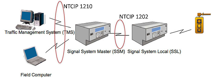
(Extended Text Description: A graphic of the typical physical architecture of an SSM deployment. Starting from the right, the graphic depicts a traffic signal head connected to a Signal System Local (SSL) controller. The SSL is then connected to a Signal System Master (SSM) controller. The SSM is then connected through two separate links to both a Traffic Management System (TMS) and a Field computer, which is represented by a laptop. The links between the SSM and TMS and the SSM and the field computer are shown as being the subject of NTCIP 1210. The link between the SSM and the SSL is shown to be the subject of NTCIP 1202.)
Source: NTCIP 1210, Fig. 3, Pg: 13
Slide 12:
Learning Objective #1
History of NTCIP 1210
Version 1: v01.53 is the "ballot ready version"
- Was recently approved
-
Has not yet been deployed
- Early deployments often reveal issues with standard
- Some potential issues have been discovered and are addressed in this course
- Those deploying equipment should seek assistance and coordinate with others
Slide 13:
Learning Objective #1
Structure of the Standard
Outline
- Section 1: General
- Section 2: Concept of Operations (ConOps)
- Section 3: Functional Requirements
- Section 4: Dialog Specifications
- Section 5: Signal System Master Object Definitions
- Section 6: SSM Block Object Definitions
- Annex A: Requirements Traceability Matrix
- Annex B: SSM Device and Information Profile
- Annex C: SSM Control Hierarchy
Slide 14:
Learning Objective #1
Structure of the Standard
Missing Components of NTCIP 1210
-
Does not include test cases
- Need to be produced for your project
Slide 15:
Learning Objective #1
Use the PRL to Trace User Needs to Requirements
- PRL introduced in Module A304a to select user needs
- Now, use the PRL to select functional requirements

(Extended Text Description: This table contains the following data:
| User Need ID | User Need | FR ID | Functional Requirement | Conformance | Support | Additional Specifications |
|---|---|---|---|---|---|---|
| 2.5.1.1 | Configure Cycle Timers and Unit Backup Time | M | Yes | |||
| 3.4.2.2.1 | Determine SSLs Currently Connected | M | Yes | |||
| 3.4.2.2.4.1 | Configure Cycle Timer Reference | O | Yes / No | |||
)
Slide 16:
Learning Objective #1
Use the PRL to Trace User Needs to Requirements
- First column identifies the clause of the user need
- Second column provides the name of the user need

(Extended Text Description: This table contains the exact same table data as Slide 15, except with the following visual changes: The User Need ID and User Need columns are highlighted. Please see Slide 15 for the complete table data.)
Slide 17:
Learning Objective #1
User Need Definition
2.5.1.1 Configure Cycle Timers and Unit Backup Time
The system owner needs to be able to determine the capabilities of the SSM. The system owner may need to configure the SSM to operate cycle timers for synchronizing the SSLs directly using a sync pulse.
Source: NTCIP 1210, Page 17
Slide 18:
Learning Objective #1
Use the PRL to Trace User Needs to Requirements
- Third column identifies the clause of the requirement
- Fourth column provides the name of the requirement
- Traceability is shown by hierarchical presentation

(Extended Text Description: This table contains the exact same table data as Slide 15, except with the following visual changes: The FR ID and Functiuonal Requirement columns are highlighted. Please see Slide 15 for the complete table data.)
Slide 19:
Learning Objective #1
Requirement Text
3.4.2.2.1 Determine SSLs Currently Connected
The SSM shall allow a TMS to determine the SSLs currently connected to the SSM.
3.4.2.2.4.1 Configure Cycle Timer Reference
The SSM shall allow the TMS to configure the specific time-of-day used for calculation of the cycle timers from the SSM.
Source: NTCIP 1210, Page 38
Slide 20:
Learning Objective #1
SSM Requirements are Well Formed
[Actor] [Action] [Target] [Constraint] [Localization]
- Actor - Identifies who or what that does the action
- Action - Identifies what is to happen
- Target - Identifies who or what receives the action
-
Optional
- Constraint - Identifies how to measure success or failure of the requirement
- Localization - Identifies the circumstances under which the requirement applies
Slide 21:
Learning Objective #1
Example SSM Requirement
[Actor] [Action] [Target] [Constraint] [Localization]

(Extended Text Description: The Example SSM Requirement slide shows the following text: "The SSM shall allow a TMS to determine the SSLs currently connected to the SSM." The text is highlighted with pullout labels as follows: "The SSM" is labeled "Target", "TMS" is labeled "Actor", "to determine" is labeled "Action", "the SSLs" is labeled "Target", and "currently connected to the SSM" is labeled "Constraint".)
Source: NTCIP 1210, Page 38
Slide 22:
Learning Objective #1
Outline of Requirements
3.3 Operational Requirements
3.3.1 Support Basic Communications
3.3.2 Support Logged Event Data
3.3.3 Manage Access
Slide 23:
Learning Objective #1
Outline of Requirements
3.4 Data Exchange Requirements
3.4.1 Collect System Detector Data
3.4.2 Manage the SSM Configuration
3.4.3 Manage the System Timing Plans
3.4.4 Monitor the SSM Operation
NOTE: Version 1 standards do not have standardized backwards compatibility issues
Slide 24:

Slide 25:
Learning Objective #1
Which of the following is not a major group of requirements in NTCIP 1210?
See Student Supplement for PRL
Answer Choices
- Collect System Detector Data
- Manage SSM Configuration
- Monitor the SSM Operation
- Backwards Compatibility Requirements
Slide 26:
Learning Objective #1
Review of answers
 a) Collect System Detector Data
Incorrect; these requirements provide for configuring and monitoring system detectors.
 b) Manage SSM Configuration
Incorrect; these requirements allow monitoring and adjusting the configuration of the SSM.
 c) Monitor the SSM Operation
Incorrect; these requirements provide for monitoring alarms and device status.
 d) Backwards Compatibility Requirements
Correct! This is the first version of NTCIP 1210 and therefore there are no backwards compatibility requirements.
Slide 27:
Summary of Learning Objective #1
Describe the requirements in NTCIP 1210
- Review components and structure of NTCIP 1210
- Use the PRL to trace user needs to requirements
- Organization and decomposition of requirements of NTCIP 1210
Slide 28:
Learning Objective #2 — Use the PRL to Specify an SSM Interface
- Use of optional requirements, constraints, and predicates within the PRL
- Specify performance criteria for functional requirements within the PRL
- Use the PRL in a specification
Slide 29:
Learning Objective #2
Conformance
- "M" indicates mandatory within the defined context
- "O" indicates optional

(Extended Text Description: This table contains the exact same table data as Slide 15, except with the following visual change: The Conformance column is highlighted. Please see Slide 15 for the complete table data.)
Slide 30:
Learning Objective #2
Conformance
Option Groups
- "O" = Optional
- ".1" = part of first option group
- "(1..*)" = One or more options from group required

(Extended Text Description: This table contains the following data:
| User Need ID | User Need | FR ID | Functional Requirement | Conformance | Support | Additional Specifications |
|---|---|---|---|---|---|---|
| 2.5.1.2.5.2 | Configure Threshold Selection | O.1 (1..*) | Yes / No | |||
| 2.5.1.2.5.3 | Configure Signature Selection | O.1 (1..*) | Yes / No | |||
Please note that the Conformance column on this slide is highlighted.)
Slide 31:
Learning Objective #2
Conformance
Conditional Conformance
- Predicates are defined prior to the PRL
- If the predicate is supported, the conformance statement applies

(Extended Text Description: This table contains the following data:
| User Need ID | User Need | FR ID | Functional Requirement | Conformance | Support | Additional Specifications |
|---|---|---|---|---|---|---|
| 2.5.1.3.1.2 | Failed System Detectors | M | Yes | |||
| 3.4.4.1.4.2 | Failed System Detectors for Threshold Selection of Timing Plans | Threshold:M | Yes / No | |||
| 3.4.4.1.4.3 | Failed System Detectors for Signature Selection of Timing Plans | Signature:M | Yes / No | |||
Please note that the Conformance column on this slide is highlighted.)
Slide 32:
Learning Objective #2
Conformance
Support
-
"Support" column indicates
- What is required in a procurement, or
- What a device supports

(Extended Text Description: This table contains the exact same table data as Slide 15, except with the following visual change: The Support column is highlighted. Please see Slide 15 for the complete table data.)
Slide 33:
Learning Objective #2
Additional Specifications
Fill in the Blanks
-
"Additional Specifications" column indicates other items that need to be specified
- Requirements = standardized text
- Specifications = project text

(Extended Text Description: This table contains the following data:
| User Need ID | User Need | FR ID | Functional Requirement | Conformance | Support | Additional Specifications |
|---|---|---|---|---|---|---|
| 3.3.1.2 | Deliver Data to the TMS | M | Yes | The Response Start Time for all requests shall not be greater than 500 ms (Default = 2000) |
Please note that the Additional Specifications column is highlighted.)
Slide 34:
Learning Objective #2
Additional Specifications
Participant Student Supplement
- Standard allows projects to add custom specifications
-
See Participant Student Supplement
- Listing of potential issues
- Sample specifications to address these issues

(Extended Text Description: This table contains the following data:
| User Need ID | User Need | FR ID | Functional Requirement | Conformance | Support | Additional Specifications |
|---|---|---|---|---|---|---|
| 3.3.3.2 | Configure Access | M | Yes | The SSM shall support at least 3 access levels in addition to the administrat or access level. |
Please note that the Additional Specifications column is highlighted.)
Slide 35:

Slide 36:
Learning Objective #2
Where is a list of potential issues and sample specifications to consider for NTCIP 1210 deployments?
Answer Choices
- In the User Needs Section of the standard
- In the Requirements Section of the standard
- In the Participant Student Supplement
- A and B
Slide 37:
Learning Objective #2
Review of answers
 a) In the text of the User Needs Section
Incorrect; user needs only define potential needs of stakeholders.
 b) In the text of the Requirements Section
Incorrect; requirements give little to no guidance on additional specifications.
 c) In the Participant Student Supplement
Correct! The Student Supplement contains a list of potential issues coupled with sample specifications that may be used.
 d) A and B
Incorrect; This information is not contained in either of these sections.
Slide 38:

Slide 39:
Learning Objective #2
Use the PRL in a Specification
Sample Project to Deploy SSMs
Suburbanville wants to upgrade its old closed-loop system so that it supports ITS standards. They want:
- Regional masters to control normal operations
- To be able to monitor detailed operations of local controllers when needed
- Time-of-day pattern selection
- Signature selection for traffic responsive operation
- Instant notification of unusual traffic conditions
Slide 40:
Learning Objective #2
Use the PRL in a Specification
General Clauses
-
Require support of all values for all NTCIP objects, unless otherwise noted
- Specific range specifications are discussed on following slides
- Define "Response Start Time"
- Include a "filled-out" version of the PRL
See example in the Participant Student Supplement
Slide 41:
Learning Objective #2
Use the PRL in a Specification
Provide Live Data

(Extended Text Description: This table contains the following data:
| User Need ID | User Need | FR ID | Functional Requirement | Conformance | Support | Additional Specifications |
|---|---|---|---|---|---|---|
| 2.4.1 | Provide Live Data | M | Yes | |||
| 3.3.1.1 | Accept Data from the TMS | M | Yes | |||
| 3.3.1.2 | Deliver Data to the TMS | M | Yes | The Response Start Time for all requests shall be not greater than 500 ms (Default 2000). | ||
| 3.3.1.3 | Explore SSM Data by the TMS | M | Yes | The Response Start Time for all requests shall be not greater than 500 ms. | ||
| 3.3.3.1 | Determine Access Settings | M | Yes | |||
| 3.3.3.2 | Configure Access | M | Yes | The SSM shall support at least 3 access-levels in addition to the administrator access level. | ||
Also please note that on this slide, all the items in the Support column are circled "Yes".)
Slide 42:
Learning Objective #2
Use the PRL in a Specification
Provide Off-line Logged Data
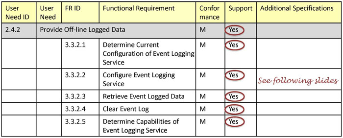
(Extended Text Description: This table contains the following data:
| User Need ID | User Need | FR ID | Functional Requirement | Conformance | Support | Additional Specifications |
|---|---|---|---|---|---|---|
| 2.4.2 | Provide Off-line Logged Data | M | Yes | |||
| 3.3.2.1 | Determine Current Configuration of Event Logging Service | M | Yes | |||
| 3.3.2.2 | Configure Event Logging Service | M | Yes | See following slides | ||
| 3.3.2.3 | Retrieve Event Logged Data | M | Yes | |||
| 3.3.2.4 | Clear Event Log | M | Yes | |||
| 3.3.2.5 | Determine Capabilities of Event Logging Service | M | Yes | |||
Also please note that on this slide, all the items in the Support column are circled "Yes".)
Slide 43:
Learning Objective #2
Structure of Off-line Logged Data
Example of What Needs to be Logged
Example: Record pattern number every time it changes for any section
- When did the event occur?
- What timing pattern was selected?
- What section was affected?
- How do I retrieve the data?
| Number | ID | Time | Value |
|---|---|---|---|
| 1 | 5 | 2013-01-01 00:00:00 | 16 |
| 2 | 3 | 2013-01-01 00:00:00 | 5 |
Slide 44:
Learning Objective #2
Structure of Off-line Logged Data
Example of What Needs to be Logged
Example: Record all changes in communication status
- When did the event occur?
- What is the new status?
- What intersection changed?
- How do I retrieve the data?
| Number | ID | Time | Value |
|---|---|---|---|
| 1 | 27 | 2012-12-30 16:30:21 | responding |
| 2 | 27 | 2012-12-30 11:05:18 | notResponding |
Slide 45:
Learning Objective #2
Structure of Off-line Logged Data
May Want to Segregate Types of Events
Event Log Table
| Class | Number | ID | Time | Value |
|---|---|---|---|---|
| 1 | 1 | 27 | 2012-12-30 16:30:21 | responding |
| 1 | 2 | 27 | 2012-12-30 11:05:18 | notResponding |
| 2 | 1 | 5 | 2013-01-01 00:00:00 | 16 |
| 2 | 2 | 3 | 2013-01-01 00:00:00 | 5 |
Slide 46:
Learning Objective #2
Event Log Configuration
What Needs to be Specified?
| Class | Number | ID | Time | Value |
|---|---|---|---|---|
| 1 | 1 | 27 | 2012-12-30 16:30:21 | responding |
| 1 | 2 | 27 | 2012-12-30 11:05:18 | notResponding |
| 2 | 1 | 5 | 2013-01-01 00:00:00 | 16 |
| 2 | 2 | 3 | 2013-01-01 00:00:00 | 5 |
- How many event classes do I need?
- How many event types (IDs) do I need?
- How many events should be stored per event class?
- Which objects should the controller be able to monitor?
Slide 47:
Learning Objective #2
Event Log Configuration
What Types of Events?
-
On change
- When the object value changes
-
Greater than (Less than)
- When value first goes above (below) reference
-
Hysteresis
- When value goes above maximum or below minimum
-
Periodic
- Every "x" seconds
-
Bitwise "and" logic
- When value can be "ANDed" with reference and result is non-zero
Slide 48:
Learning Objective #2
Use the PRL in a Specification
Connect Communication Networks

(Extended Text Description: This table contains the following data:
| User Need ID | User Need | FR ID | Functional Requirement | Conformance | Support | Additional Specifications |
|---|---|---|---|---|---|---|
| 2.4.3 | Connect Communication Networks | M | Yes | |||
| 3.3.1.4 | Accept Data from the SSLs | M | Yes | |||
| 3.3.1.5 | Deliver Data to the SSLs | M | Yes | |||
| 3.3.1.6 | Explore SSL Data by the TMS | M | Yes | |||
| 3.3.1.7 | TMS Acceptance of Data fr SSL | M | Yes | |||
| 3.3.1.8 | TMS Delivery of Data to SSL | M | Yes | |||
| 3.3.3.1 | Determine Access Settings | M | Yes | |||
| 3.3.3.2 | Configure Access | M | Yes | |||
Also please note that on this slide, all the items in the Support column are circled "Yes".)
See Participant Student Supplement for discussion of potential issues and three possible solutions that could be added to your specification.
Slide 49:
Learning Objective #2
Use the PRL in a Specification
Support Legacy Communication Networks

(Extended Text Description: This table contains the following data:
| User Need ID | User Need | FR ID | Functional Requirement | Conformance | Support | Additional Specifications |
|---|---|---|---|---|---|---|
| 2.4.4 | Support Legacy Communication Networks | O | Yes / No | |||
| 3.3.1.9.1 | Configure Using Block Objects | M | Yes | |||
| 3.3.1.9.2 | Retrieve Block Objects | M | Yes | |||
| 3.3.1.9.3 | Retrieve Block Status | M | Yes | |||
| 3.3.1.9.4 | Support STMP | O | Yes / No | |||
Also please note that the "No" in the first data row of the Support column is circled.)
Slide 50:
Learning Objective #2
Use the PRL in a Specification
Configure Cycle Timers and Unit Backup Time
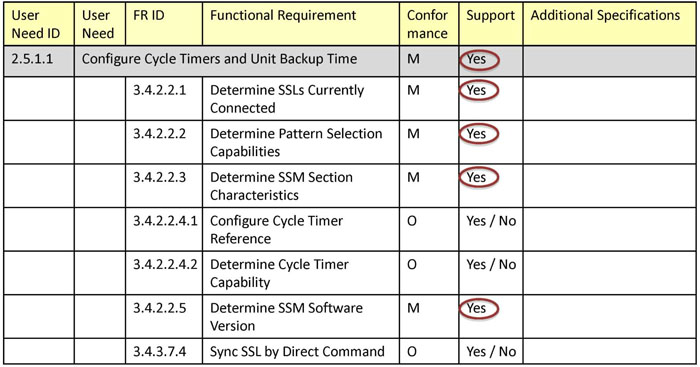
(Extended Text Description: This table contains the following data:
| User Need ID | User Need | FR ID | Functional Requirement | Conformance | Support | Additional Specifications |
|---|---|---|---|---|---|---|
| 2.5.1.1 | Configure Cycle Timers and Unit Backup Time | M | Yes | |||
| 3.4.2.2.1 | Determine SSLs Currently Connected | M | Yes | |||
| 3.4.2.2.2 | Determine Pattern Selection Capabilities | M | Yes | |||
| 3.4.2.2.3 | Determine SSM Section Characteristics | M | Yes | |||
| 3.4.2.2.4.1 | Configure Cycle Timer Reference | O | Yes / No | |||
| 3.4.2.2.4.2 | Determine Cycle Timer Capability | O | Yes / No | |||
| 3.4.2.2.5 | Determine SSM Software Version | M | Yes | |||
| 3.4.3.7.4 | Sync SSL by Direct Command | O | Yes / No | |||
Also please note that on this slide, all the items in the Support column are circled "Yes" except rows 3.4.2.2.4.1, 3.4.2.2.4.2, and 3.4.3.7.4.)
Slide 51:
Learning Objective #2
Use the PRL in a Specification
Configure Cycle Timers and Unit Backup Time
-
Sync Pulse
- Issued at start of every cycle
- Issued by SSM
- Used when local clocks are not accurate
-
Clock synchronization
- Typically synchronized once a day
- Can use any common time source (GPS, WWV, etc.)
- Typical for modern controllers
Slide 52:
Learning Objective #2
Use the PRL in a Specification
Configure Cycle Timers and Unit Backup Time
Need to define range specifications for:
- Number of sections
- Number of SSLs
- Number of patterns

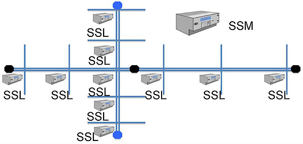
(Extended Text Description: A graphic representing a sample signal system. There is a major arterial running horizontally and a second major arterial running vertically that intersects with the first arterial. In addition to the intersection of the major arterials, there are two minor cross-streets intersecting the vertical arterial above the main intersection and two below. There are also two minor cross-streets intersecting the major horizontal intersection to the left of the main intersection and three to the right. All ten intersections are shown to have their own SSL, indicating that these are signalized intersections. Finally, there is a SSM depicted that controls all of the SSLs.)
Slide 53:
Learning Objective #2
Use the PRL in a Specification
Configure Cycle Timers and Unit Backup Time
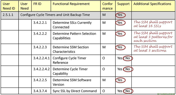
(Extended Text Description: This table contains the following data:
| User Need ID | User Need | FR ID | Functional Requirement | Conformance | Support | Additional Specifications |
|---|---|---|---|---|---|---|
| 2.5.1.1 | Configure Cycle Timers and Unit Backup Time | M | Yes | |||
| 3.4.2.2.1 | Determine SSLs Currently Connected | M | Yes | The SSM shall support at least 16 SSLs | ||
| 3.4.2.2.2 | Determine Pattern Selection Capabilities | M | Yes | The SSM shall support at least 3 patterns for each section | ||
| 3.4.2.2.3 | Determine SSM Section Characteristics | M | Yes | The SSM shall support at least 3 sections. | ||
| 3.4.2.2.4.1 | Configure Cycle Timer Reference | O | Yes / No | |||
| 3.4.2.2.4.2 | Determine Cycle Timer Capability | O | Yes / No | |||
| 3.4.2.2.5 | Determine SSM Software Version | M | Yes | |||
| 3.4.3.7.4 | Sync SSL by Direct Command | O | Yes / No | |||
Also please note that on this slide, all the items in the Support column are circled "Yes" except rows 3.4.2.2.4.1, 3.4.2.2.4.2, and 3.4.3.7.4, which are circled "No".)
Slide 54:
Learning Objective #2
Use the PRL in a Specification
Manage Section Definition Set

(Extended Text Description: This table contains the following data:
| User Need ID | User Need | FR ID | Functional Requirement | Conformance | Support | Additional Specifications |
|---|---|---|---|---|---|---|
| 2.5.1.2.1 | Manage Section Definition Set | M | Yes | |||
| 3.4.3.1.1 | Configure Section Assignment | M | Yes | |||
| 3.4.3.1.2 | Retrieve Section Assignment | M | Yes | |||
| 3.4.3.1.3 | Configure Section Characteristics | M | Yes | |||
Also please note that on this slide, all the items in the Support column are circled "Yes".)
Slide 55:
Learning Objective #2
Use the PRL in a Specification
Implement a Manually Selected Plan

(Extended Text Description: This table contains the following data:
| User Need ID | User Need | FR ID | Functional Requirement | Conformance | Support | Additional Specifications |
|---|---|---|---|---|---|---|
| 2.5.1.2.2 | Implement a Manually Selected Plan | M | Yes | |||
| 3.4.3.3 | TMS Override of Plan Selection | M | Yes | |||
Also please note that on this slide, all the items in the Support column are circled "Yes".)
Slide 56:
Learning Objective #2
Use the PRL in a Specification
Implement Plan Based on TMS Command

(Extended Text Description: This table contains the following data:
| User Need ID | User Need | FR ID | Functional Requirement | Conformance | Support | Additional Specifications |
|---|---|---|---|---|---|---|
| 2.5.1.2.3 | Implement Plan Based on TMS Command | M | Yes | |||
| 3.4.3.6.1 | TMS Override of SSM Algorithm of Timebase Timing Plan | M | Yes | |||
| 3.4.3.6.2 | SSM Instruct SSLs to Engage TMS Timing Plan | M | Yes | |||
| 3.4.3.6.3 | Set Maximum Time Without TMS Control | M | Yes | |||
Also please note that on this slide, all the items in the Support column are circled "Yes".)
Slide 57:
Learning Objective #2
Use the PRL in a Specification
Implement Plan Based on Timebase Schedule

(Extended Text Description: This table contains the following data:
| User Need ID | User Need | FR ID | Functional Requirement | Conformance | Support | Additional Specifications |
|---|---|---|---|---|---|---|
| 2.5.1.2.4 | Implement Plan Based on Timebase Schedule | M | Yes | |||
| 3.4.2.1 | Synchronize SSM Clock with TMS | M | Yes | |||
| 3.4.3.4 | Configure SSM Schedule | M | Yes | |||
| 3.4.3.6.2 | SSM Instruct SSLs to Engage TMS Timing Plan | M | Yes | |||
Also please note that on this slide, all the items in the Support column are circled "Yes".)
Slide 58:
Learning Objective #2
Timebase Schedule
Number of Timebase Schedule Entries
| Number | Month | Day | Date | Day Plan |
|---|---|---|---|---|
| 1 | All | M-F | All | 1 |
| 2 | All | S-S | All | 2 |
| 3 | Jan | All | 1 | 3 |
| 4 | Dec | Fri | 31 | 3 |
| 5 | Jan | Mon | 2 | 3 |
| 6 | Jan | Mon | 15-21 | 3 |
| ... | ... | ... | ... | ... |
| 17 | Dec | M-F | All | 4 |
| 18 | Dec | S-S | All | 5 |
Slide 59:
Learning Objective #2
Timebase Schedule
Number of Day Plans and Day Plan Events
| Number | Event # | Hour | Minute | Action |
|---|---|---|---|---|
| 1 | 1 | 05 | 00 | 1 |
| 1 | 2 | 10 | 00 | 2 |
| 1 | 3 | 15 | 00 | 3 |
| 1 | 4 | 16 | 00 | 4 |
| 1 | 5 | 22 | 00 | 5 |
| ... | ... | ... | ... | ... |
Slide 60:
Learning Objective #2
Timebase Schedule
Number of SSM Actions and Action Tasks
| Number | Task Number | Task Section | Pattern Enable | Pattern | Special Function Enable | Special Function |
|---|---|---|---|---|---|---|
| 1 | 1 | 1 & 2 | enabled | 1 | notEnabled | 0 |
| 2 | 1 | 1 | enabled | 2 | notEnabled | 0 |
| 2 | 2 | 2 | notEnabled | 0 | notEnabled | 0 |
| 3 | 1 | 2 | enabled | 3 | notEnabled | 0 |
| 4 | 1 | 1 | enabled | 3 | notEnabled | 0 |
Slide 61:
Learning Objective #2
Structure of Off-line Logged Data
Local Time and Daylight Savings
Local time determined by:
- Global Time, in Coordinated Universal Time (UTC)
- Standard time zone
-
Daylight savings mode (configurable)
- 2nd Sunday in March to 1st Sunday in November
- 2 a.m. local time
| Number | BeginMonth | BeginOccur | BeginDoW | BeginDoM | BeginSecs |
|---|---|---|---|---|---|
| 1 | March | Second | Sunday | 1 | 7200 |
| EndMonth | EndOccur | EndDoW | EndDoM | EndSecs | Adjust |
| November | First | Sunday | 1 | 7200 | 3600 |
Slide 62:
Learning Objective #2
Use the PRL in a Specification
Implement Plan Based on Timebase Schedule
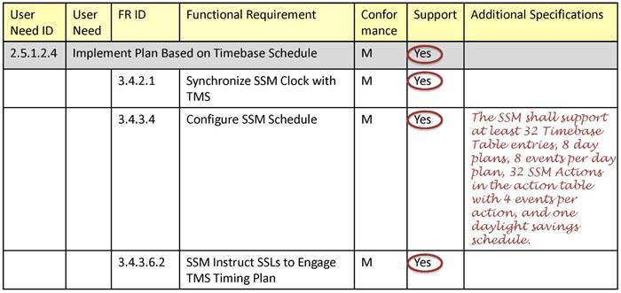
(Extended Text Description: This table contains the following data:
| User Need ID | User Need | FR ID | Functional Requirement | Conformance | Support | Additional Specifications |
|---|---|---|---|---|---|---|
| 2.5.1.2.4 | Implement Plan Based on Timebase Schedule | M | Yes | |||
| 3.4.2.1 | Synchronize SSM Clock with TMS | M | Yes | |||
| 3.4.3.4 | Configure SSM Schedule | M | Yes | The SSM shall support at least 32 Timebase Table entries, 8 day plans, 8 events per day plan, 32 SSM Actions in the action table with 4 events per action, and one daylight savings schedule. | ||
| 3.4.3.6.2 | SSM Instruct SSLs to Engage TMS Timing Plan | M | Yes | |||
Also please note that on this slide, all the items in the Support column are circled "Yes".)
Slide 63:
Learning Objective #2
Use the PRL in a Specification
Configure Traffic Responsive Mode

(Extended Text Description: This table contains the following data:
| User Need ID | User Need | FR ID | Functional Requirement | Conformance | Support | Additional Specifications |
|---|---|---|---|---|---|---|
| 2.5.1.2.5.1 | Configure Traffic Responsive Mode | M | Yes | |||
| 3.4.1.1 | Assign System Detectors | M | Yes | |||
| 3.4.3.5.1 | Select Algorithm | M | Yes | |||
| 3.4.3.5.2 | Accept Pattern Selection Frequency | M | Yes | |||
| 3.4.3.5.3.8 | Instruct SSLs to Engage Threshold Timing Plan | M | Yes | |||
Also please note that on this slide, all the items in the Support column are circled "Yes".)
Slide 64:
Learning Objective #2
Configure Traffic Responsive Mode
Number of System Detectors
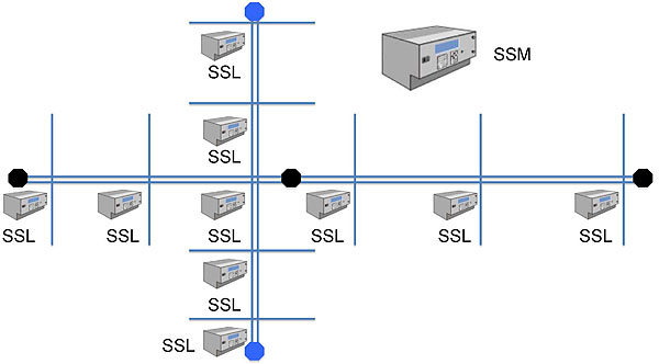
(Extended Text Description: The same graphic representing a sample signal system as discussed on Slide 52 with the addition of system detectors. One detector is shown at each of the four entry points to the system, i.e., one at the left end, one at the top, one at the right end, and one at the bottom. In addition, there is one additional detector located just to the right of the main intersection between the two arterials. All three system detectors located along the horizontal arterial are shown in black and the two detectors on the vertical arterial are shown in blue.)
Slide 65:
Learning Objective #2
Use the PRL in a Specification
Configure Traffic Responsive Mode
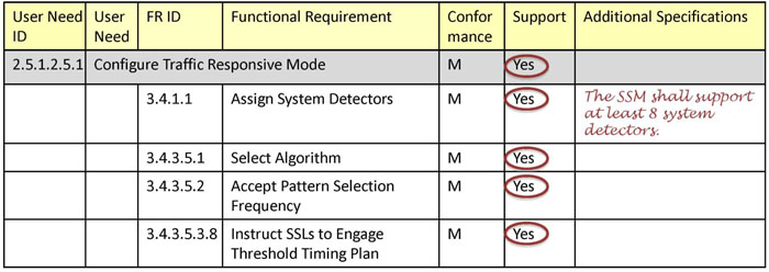
(Extended Text Description: This table contains the following data:
| User Need ID | User Need | FR ID | Functional Requirement | Conformance | Support | Additional Specifications |
|---|---|---|---|---|---|---|
| 2.5.1.2.5.1 | Configure Traffic Responsive Mode | M | Yes | |||
| 3.4.1.1 | Assign System Detectors | M | Yes | The SSM shall support at least 8 system detectors. | ||
| 3.4.3.5.1 | Select Algorithm | M | Yes | |||
| 3.4.3.5.2 | Accept Pattern Selection Frequency | M | Yes | |||
| 3.4.3.5.3.8 | Instruct SSLs to Engage Threshold Timing Plan | M | Yes | |||
Also please note that on this slide, all the items in the Support column are circled "Yes".)
Slide 66:
Learning Objective #2
Use the PRL in a Specification
Configure Threshold Selection

(Extended Text Description: This table contains the following data:
| UN ID | UN | FR ID | Functional Requirement | Conform | Support | Additional Specifications |
|---|---|---|---|---|---|---|
| 2.5.1.2.5.2 | Configure Threshold Selection | O.1 (1..*) | Yes / No | |||
| 3.4.1.2 | Configure Detector Grouping | M | Yes | |||
| 3.4.1.3 | Configure Group Smooth | M | Yes | |||
| 3.4.1.4 | Configure Override Smoothing | M | Yes | |||
| 3.4.1.5 | Configure Minimum Samples | M | Yes | |||
| 3.4.1.6 | Configure Avg or Highest Value | M | Yes | |||
| 3.4.3.5.3.1 | Config Directional Thresholds | M | Yes | |||
| 3.4.3.5.3.2 | Configure Cycle Thresholds | M | Yes | |||
| 3.4.3.5.3.3 | Configure Split Thresholds | M | Yes | |||
| 3.4.3.5.3.4 | Configure Minimum Detectors | M | Yes | |||
| 3.4.3.5.3.5 | Configure Queue Thresholds | O | Yes / No | |||
| 3.4.3.5.3.6 | Config Occupancy Thresholds | O | Yes / No | |||
| 3.4.3.5.3.7 | Config Non-Arterial Thresholds | O | Yes / No | |||
| 3.4.3.5.3.8 | Instruct SSLs to Engage Plan | M | Yes | |||
Also please note that the "No" in the first data row of the Support column is circled.)
Slide 67:
Learning Objective #2
Configure Threshold Selection
Range Specifications
- Number of Detectors per Group
- Number of Levels in Cycle Threshold Channel
- Number of Levels in Split Threshold Channel
- Number of Levels in Offset Threshold Channel
Slide 68:
Learning Objective #2
Configure Threshold Selection
Options
-
May be concerned about traffic backups
- Queue detector override option
- Occupancy detector override option
- Non-arterial detector override option
Slide 69:
Learning Objective #2
Use the PRL in a Specification
Configure Signature Selection

(Extended Text Description: This table contains the following data:
| User Need ID | User Need | FR ID | Functional Requirement | Conformance | Support | Additional Specifications |
|---|---|---|---|---|---|---|
| 2.5.1.2.5.3 | Configure Signature Selection | 0.1 (1..*) | Yes / No | |||
| 3.4.3.5.4.1 | Configure Signature Parameters | M | Yes | |||
| 3.4.3.5.4.2 | Instruct SSLs to Engage Signature Timing Plan | M | Yes | |||
Also please note that on this slide, all the items in the Support column are circled "Yes".)
Slide 70:
Learning Objective #2
Configure Signature Selection
Range Specifications
- Number of Signatures
- Number of Signature Detectors
Slide 71:
Learning Objective #2
Use the PRL in a Specification
Configure Plan Selection Mode Schedule

(Extended Text Description: This table contains the following data:
| User Need ID | User Need | FR ID | Functional Requirement | Conformance | Support | Additional Specifications |
|---|---|---|---|---|---|---|
| 2.5.1.2.6 | Configure Plan Selection Mode Schedule | M | Yes | |||
| 3.4.3.2 | Configure Plan Selection Mode Schedule | M | Yes | |||
Also please note that on this slide, all the items in the Support column are circled "Yes".)
Slide 72:
Learning Objective #2
Use the PRL in a Specification
Synchronize Clocks of SSLs

(Extended Text Description: This table contains the following data:
| User Need ID | User Need | FR ID | Functional Requirement | Conformance | Support | Additional Specifications |
|---|---|---|---|---|---|---|
| 2.5.1.2.7 | Synchronize Clocks of SSLs | M | Yes | |||
| 3.4.3.7.1 | Accept User-Defined Period for SSL Clock Synchronization | M | Yes | |||
| 3.4.3.7.2 | Periodically Set Clocks of SSLs | M | Yes | |||
| 3.4.3.7.3 | Instruct SSM to Set Clocks of SSLs | M | Yes | |||
Also please note that on this slide, all the items in the Support column are circled "Yes".)
Slide 73:
Learning Objective #2
Use the PRL in a Specification
Configure Cycle Length by Plan

(Extended Text Description: This table contains the following data:
| User Need ID | User Need | FR ID | Functional Requirement | Conformance | Support | Additional Specifications |
|---|---|---|---|---|---|---|
| 2.5.1.2.8 | Configure Cycle Length by Plan | SyncPulse:M | Yes / No | |||
| 3.4.2.2.6 | Accept Cycle Length by Plan | M | Yes | |||
Also please note that the "No" in the first data row of the Support column is circled.)
Slide 74:
Learning Objective #2
Use the PRL in a Specification
Manage Alarms
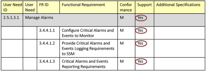
(Extended Text Description: This table contains the following data:
| User Need ID | User Need | FR ID | Functional Requirement | Conformance | Support | Additional Specifications |
|---|---|---|---|---|---|---|
| 2.5.1.3.1 | Manage Alarms | M | Yes | |||
| 3.4.4.1.1 | Configure Critical Alarms and Events to Monitor | M | Yes | |||
| 3.4.4.1.2 | Provide Critical Alarms and Events Logging Requirements to SSM | M | Yes | |||
| 3.4.4.1.3 | Critical Alarms and Events Reporting Requirements | M | Yes | |||
Also please note that on this slide, all the items in the Support column are circled "Yes".)
Slide 75:
Learning Objective #2
Use the PRL in a Specification
Loss of Control of SSLs
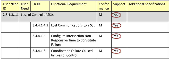
(Extended Text Description: This table contains the following data:
| User Need ID | User Need | FR ID | Functional Requirement | Conformance | Support | Additional Specifications |
|---|---|---|---|---|---|---|
| 2.5.1.3.1.1 | Loss of Control of SSLs | M | Yes | |||
| 3.4.4.1.4.1 | Lost Communications to a SSL | M | Yes | |||
| 3.4.4.1.5 | Configure Intersection Non-Responsive Time to Constitute Failure | M | Yes | |||
| 3.4.4.1.6 | Coordination Failure Caused by Loss of Control | M | Yes | |||
Also please note that on this slide, all the items in the Support column are circled "Yes".)
Slide 76:
Learning Objective #2
Use the PRL in a Specification
Failed System Detectors

(Extended Text Description: This table contains the following data:
| User Need ID | User Need | FR ID | Functional Requirement | Conformance | Support | Additional Specifications |
|---|---|---|---|---|---|---|
| 2.5.1.3.1.2 | Failed System Detectors | M | Yes | |||
| 3.4.4.1.4.2 | Failed System Detectors for Threshold Selection of Timing Plans | Threshold: M | Yes / No | |||
| 3.4.4.1.4.3 | Failed System Detectors for Signature Selection of Timing Plans | Signature: M | Yes / No | |||
Also please note that on this slide, all the items in the Support column are circled "Yes" except row 3.4.4.1.4.2 which is circled "No".)
Slide 77:
Learning Objective #2
Use the PRL in a Specification
Other Alarms Within a SSL

(Extended Text Description: This table contains the following data:
| User Need ID | User Need | FR ID | Functional Requirement | Conformance | Support | Additional Specifications |
|---|---|---|---|---|---|---|
| 2.5.1.3.1.3 | Other Alarms Within a SSL | M | Yes | |||
| 3.4.4.1.4.4 | SSL Alarms and Events | M | Yes | |||
Also please note that on this slide, all the items in the Support column are circled "Yes".)
Slide 78:
Learning Objective #2
Use the PRL in a Specification
Forward SSM Alarms and Events

(Extended Text Description: This table contains the following data:
| User Need ID | User Need | FR ID | Functional Requirement | Conformance | Support | Additional Specifications |
|---|---|---|---|---|---|---|
| 2.5.1.3.1.4 | Forward SSM Alarms and Events | M | Yes | |||
| 3.3.2.2 | Configure Event Logging Service | M | Yes | |||
| 3.3.2.3 | Retrieve Event Logged Data | M | Yes | |||
Also please note that on this slide, all the items in the Support column are circled "Yes".)
Slide 79:
Learning Objective #2
Use the PRL in a Specification
Manage System Display Data

(Extended Text Description: This table contains the following data:
| User Need ID | User Need | FR ID | Functional Requirement | Conformance | Support | Additional Specifications |
|---|---|---|---|---|---|---|
| 2.5.1.3.2 | Manage System Display Data | M | Yes | The Response Start Time for all requests shall be not greater than 500 ms | ||
| 3.4.3.1.2 | Retrieve Section Assignment | M | Yes | |||
| 3.4.4.2.1 | Provide Time Plan for Ea. Sect. | M | Yes | |||
| 3.4.4.2.2 | Provide Cycle Len. for Ea. Sect. | M | Yes | |||
| 3.4.4.2.3 | Provide Display Status of the Signal Displays for Each SSL | M | Yes | |||
| 3.4.4.2.4 | Provide Current Traffic Responsive Comparison | O | Yes / No | |||
| 3.4.4.2.5 | Provide Mode and Pattern Number for Each SSL | M | Yes | |||
| 3.4.4.2.6 | Provide Status for Each SSL | M | Yes | |||
| 3.4.4.2.7 | Provide Status for Each System Detector | M | Yes | |||
Also please note that on this slide, all the items in the Support column are circled "Yes".)
Slide 80:
Learning Objective #2
Use the PRL in a Specification
Monitor Traffic Conditions

(Extended Text Description: This table contains the following data:
| User Need ID | User Need | FR ID | Functional Requirement | Conformance | Support | Additional Specifications |
|---|---|---|---|---|---|---|
| 2.5.1.3.3 | Monitor Traffic Conditions | M | Yes | |||
| 3.4.1.7 | SSM Collect Volume and Occupancy Data | M | Yes | |||
| 3.4.1.8 | TMS Collect Volume and Occupancy Data | M | Yes | |||
Also please note that on this slide, all the items in the Support column are circled "Yes".)
Slide 81:
Learning Objective #2
Use the PRL in a Specification
Manage SSLs

(Extended Text Description: This table contains the following data:
| User Need ID | User Need | FR ID | Functional Requirement | Conformance | Support | Additional Specifications |
|---|---|---|---|---|---|---|
| 2.5.2 | Manage SSLs | O | Yes / No | |||
| 3.3.1.6 | Explore SSL Data by the TMS | M | Yes | |||
| 3.3.1.7 | TMS Acceptance of Data from the SSL | M | Yes | |||
| 3.3.1.8 | TMS Delivery of Data to the SSL | M | Yes | |||
| 3.4.2.3 | Configure Connected SSLs | M | Yes | |||
Also please note that the "No" in the first data row of the Support column is circled.)
Slide 82:

Slide 83:
Learning Objective #2
When should a requirement with a conformance "Threshold:M" be selected?
From NTCIP 1210 Clause 3.2.3.2 and Participant Student Supplement Page 2
| Predicate | Section |
|---|---|
| SyncPulse | 2.5.1.2.8 |
| Threshold | 2.5.1.2.5.2 |
| Signature | 2.5.1.2.5.3 |
Answer Choices
- Only when User Need 2.5.1.2.5.2 is selected
- Always
- Only when Requirement 3.4.4.1.4.2 is selected
- Only when Requirement 3.4.3.5.3.5 is selected
Slide 84:
Learning Objective #2
Review of answers
 a) Only when User Need 2.5.1.2.5.2 is selected
Correct! Clause 3.2.3.2 of the standard maps the predicate "Threshold" to Clause 2.5.1.2.5.,
 b) Always
Incorrect; The predicate means that support is conditional upon another selection.
 c) Only when Requirement 3.4.4.1.4.2 is selected
Incorrect; this requirement has this conformance and thus this would result in circular logic.
 d) Only when Requirement 3.4.3.5.3.5 is selected
Incorrect; the conformance may be mandatory even when 3.4.3.5.3.5 (Override Thresholds) is not selected.
Slide 85:
Learning Objective #2
Using the PRL in a Specification
Part of Interface Specification
- A completed PRL defines the data requirements for the NTCIP interface
- When combined with the communication specification (See Module C101), it forms an interface specification
-
A deployment may need multiple interface specifications
- Management systems that support multiple devices
- May need support for legacy protocol
Slide 86:
Learning Objective #2
Using the PRL in a Specification
Consistency
- The interface specification must be consistent with the remainder of the specification
-
Interface requires ability to synchronize clocks
- Implies existence of clock in SSM
- Requires software logic for SSM to periodically synchronize clocks
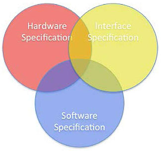
(Extended Text Description: Three overlapping circles. One is labeled "Hardware Specification", the next is labeled "Software Specification", and the final one is labeled "Interface Specification". The overlap symbolizes that each of these specifications are likely to cover topics that relate to other portions of the specifications and that care must be taken to avoid any conflict between these distinct sections of the overall procurement package.)
Slide 87:
Learning Objective #2
Using the PRL in a Specification
Sample Text
- The PRL should be properly introduced within the specification
- Copyright disclaimer should appear with the PRL
- Refer to the Student Supplement for additional text, including "Additional Specifications"
Slide 88:
Summary of Learning Objective #2
Use the PRL to Specify an SSM Interface
- Use of optional requirements, constraints, and predicates within the PRL
- Specify performance criteria for functional requirements within the PRL
- Specify limits or ranges for functional requirements within the PRL
- Use the PRL in a specification
Slide 89:
Learning Objective #3 — Achieve Interoperability and Interchangeability
- How the RTM traces to a single design
- How to compare for interoperability
- How to compare for interchangeability
Slide 90:
Learning Objective #3
Interoperability and Interchangeability
Requirements Traceability Matrix
- Annex A contains the RTM
- Maps requirements to a specific design
-
Several ambiguities in the current draft
- Early deployments should coordinate with industry experts
Slide 91:
Learning Objective #3
Interoperability and Interchangeability
Requirements Traceability Matrix
- First two columns reference a requirement

(Extended Text Description: This table contains the following data:
| Func Req't Reference | Functional Requirement | Dialog Reference | Object Reference | Object | Comments (Informative) |
|---|---|---|---|---|---|
| 3.3.1.6 | Explore SSL Data by the TMS | 4.2.13 | 5.7 Group | PMPP Routing | TMS to SSL message management |
| 3.3.1.9.2 | Retrieve Block Objects | 4.2.11 | 5.25.1 | ssmBlockGetControl | |
| 5.25.2 | ssmBlockData |
Please note that on this slide, the first two columns of this table, Func Req't Reference and Functional Requirement, are highlighted.)
Slide 92:
Learning Objective #3
Interoperability and Interchangeability
Requirements Traceability Matrix
-
The third column defines the associated dialog
- A requirement traces to only one dialog

(Extended Text Description: This table contains the exact same table data as Slide 91, except with the following visual change: The Dialog Reference column is highlighted. Please see Slide 91 for the complete table data.)
Slide 93:
Learning Objective #3
Interoperability and Interchangeability
Requirements Traceability Matrix
-
The fourth and fifth columns define the associated objects
- All objects that trace to the requirement must be supported, if the requirement is supported
- Many-to-many relationships between requirements and objects

(Extended Text Description: This table contains the exact same table data as Slide 91, except with the following visual changes: The Object Reference and Object columns are highlighted. Please see Slide 91 for the complete table data.)
Slide 94:
Learning Objective #3
Interoperability and Interchangeability
Requirements Traceability Matrix
-
The sixth column provides comments
- These are defined as informative and have no normative standing

(Extended Text Description: This table contains the exact same table data as Slide 91, except with the following visual change: The Comments (Informative) column is highlighted. Please see Slide 91 for the complete table data.)
Slide 95:
Learning Objective #3
Interoperability and Interchangeability
Requirements Traceability Matrix
RTM Maps each requirement to a specific design
- A precise dialog
- A precise list of objects
Slide 96:
Learning Objective #3
Interoperability and Interchangeability
Comparisons of PRLs for Interoperability
- RTM provides interoperability at individual requirement level
- PRL indicates which requirements are supported/required
-
Comparison of PRLs allow quick determination of interoperability
- Ability of two or more systems to exchange information and use the information that has been exchanged
Interoperability

(Extended Text Description: A graphic representing interoperability. On the left side of the figure is a desktop computer, which has a box labeled "Data Object X" to its immediate right. On the right side of the figure is a controller, which has an identical box with the same "Data Object X" label to its immediate left. The two "Data Object X" boxes are connected with a bi-directional line labeled "NTCIP" to indicate that the information can be exchanged across the link.)
Slide 97:
Learning Objective #3
Interoperability and Interchangeability
Comparisons of PRLs for Interoperability
-
Both TMS and SSM support a feature
- Interoperability provided
-
TMS supports, SSM does not
- TMS can still use other features (typically)
- TMS can still interoperate with feature with other devices
-
SSM Supports, TMS does not
- Feature could be used by other/future TMS
- Feature can potentially be used manually
Slide 98:
Learning Objective #3
Interoperability and Interchangeability
Comparisons of PRLs for Interchangeability
-
Comparison of PRLs allow quick determination of interchangeability
- Ability to replace one component with another from a different manufacturer
Interchangeability

(Extended Text Description: A graphic representing interchangeability. The graphic is similar to the one on Slide 96, but the single controller is replaced with two different controllers, one labeled X and the other labeled Y, indicating that they are from different manufacturers. Between the two controllers is the word "OR" indicating that either controller can be used.)
Slide 99:
Learning Objective #3
Interoperability and Interchangeability
Comparisons of PRLs for Interchangeability
-
Both support a feature
- Equipment is interchangeable for feature
-
New equipment supports, old equipment does not
- New equipment is interchangeable for feature (meets or exceeds)
-
Old equipment supports, new does not
-
Feature will not be supported
 Is feature really needed?
-
Feature will not be supported
Slide 100:

Slide 101:
Learning Objective #3
What does the following table mean?
| Func Req't Reference | Functional Requirement | Dialog Reference | Object Reference | Object |
|---|---|---|---|---|
| 3.4.1.1 | Assign System Detectors | 4.2.1 | 5.12.1 | maxSensorSources |
| 5.12.2.1.2 | sensorSourcelntersection | |||
| 5.12.2.1.3 | sensorSourceDetNumber | |||
| 5.12.2.1.7 | sensorSourceVolumeFactor | |||
| 5.12.2.1.11 | sensorSourceOccWeighting |
Answer Choices
- All of the objects must be supported
- At least one of the objects must be supported
- All of the objects must be supported, if the requirement is supported
- At least one of the objects must be supported, if the requirement is supported
Slide 102:
Learning Objective #3
Review of answers
 a) All of the objects must be supported
Incorrect; they only need to be supported if the requirement has been selected in the PRL.
 b) At least one of the objects must be supported
Incorrect; if the requirement is selected, all of the indicated objects must be supported.
 c) All of the objects must be supported, if the requirement is supported
Correct!
 d) At least one of the objects must be supported, if the requirement is supported
Incorrect; if the requirement is selected, all of the indicated objects must be supported.
Slide 103:
Summary of Learning Objective #3
Achieve Interoperability and Interchangeability
- The RTM traces requirements to a single design
- The PRL and RTM allow easy checks for interoperability
- The PRL and RTM allow easy checks for interchangeability
Slide 104:
Learning Objective #4 — Understand NTCIP 1210 Dialogs
- Example NTCIP 1210 dialog to an SSM
- Example NTCIP 1210 dialog with an SSL
Slide 105:
Learning Objective #4
Understand NTCIP 1210 Dialogs
Dialog 4.2.1

(Extended Text Description: A UML sequence diagram depicting communications between a Transportation Management System (TMS) and a Signal System Master (SSM). The sequence begins with the TMS sending a request for "Get(maxSensorSources.0)" to the SSM. The SSM returns a response to this request to the TMS. For each sensor source, the TMS then sends a request to "Set(sensorSourceIntersection.x, sensorSourceDetNumber.x, sensorSourceVolumeFacor.x, sensorSourceOccWeighting.x)" to the SSM. Finally, the SSM responds to each such "set" command.)
Slide 106:
Learning Objective #4
Understand NTCIP 1210 Dialogs
TMS _ SSM
-
All objects referenced anywhere in dialog are shown in RTM
- RTM provides traceability
- Dialog gives sequencing rules
| Func Req't Reference | Functional Requirement | Dialog Reference | Object Reference | Object |
|---|---|---|---|---|
| 3.4.1.1 | Assign System Detectors | 4.2.1 | 5.12.1 | maxSensorSources |
| 5.12.2.1.2 | sensorSourcelntersection | |||
| 5.12.2.1.3 | sensorSourceDetNumber | |||
| 5.12.2.1.7 | sensorSourceVolumeFactor | |||
| 5.12.2.1.11 | sensorSourceOccWeighting |
Slide 107:
Learning Objective #4
Understand NTCIP 1210 Dialogs
TMS _ SSM _ SSL
2.4.3 Connect Communication Networks
The SSM needs to provide the ability to connect communication networks.
3.3.1.8 TMS Delivery of Data to the SSL
The SSM shall provide a pass-through capability for the TMS to deliver data to the SSL.
There are potential issues as we will discuss on the following slides along with three possible work-arounds
Slide 108:
Learning Objective #4
Use the PRL in a Specification
Connect Communication Networks

(Extended Text Description: A UML sequence diagram depicting communications among a Transportation Management System (TMS), a Signal System Master (SSM), and a Signal System Local (SSL). The sequence starts with the TMS sending a request to the SSM for "Get (maxMsgRouted.0)". The SSM then returns a response to this request. For each SSL object to be sent, the TMS then sends the SSM a message labeled "Set(sslCommand.x, sslNumber.x, sslCommandFrequency.x)". The SSM then sends a response message to the TMS for each "set" message. Until the command is cleared, the SSM then sends the "sslCommand.x" to the SSL at the sslCommandFrequency.x and the SSL responds. The SSM then stores this response in sslResponse.x. Finally, the TMS repeatedly retrieves the data by sending a request for "Get(sslCommandTimestamp.x, sslResponse.x, sslResponseTimestamp.x, sslResponseSequence.x, sslResponseStatus.x)" and the SSM responds.)
Slide 109:
Learning Objective #4
Use the PRL in a Specification
Connect Networks _ Support for Any Message
-
Allows sending any packetized data
- Any SNMP request
- Any STMP request
- Any message conforming to another standard
- Any message in a proprietary format
-
The SSM does not need to understand the contents of the message
- Only the SSL needs to understand
Slide 110:
Learning Objective #4
Use the PRL in a Specification
Connect Networks _ Potential Issue #1
sslResponse contains "ALL responses from the SSL." Most would likely to interpret this to mean:
-
The last packet received from the SSL, which may be:
- A response to the sslCommand
- A response to another sslCommand
- A response to an automated request from the SSM
- An unsolicited report from the SSL
Actual response may be overwritten before TMS can retrieve
Slide 111:
Learning Objective #4
Use the PRL in a Specification
Connect Networks _ Work Around #1
The user need does not identify bandwidth constraints.
-
Could use IP for connecting networks
- Needs high-speed connection
Slide 112:
Learning Objective #4
Use the PRL in a Specification
Connect Networks _ Work Around #2
-
Could use the pre-defined commands
- Set time
- Set sync control
- Set pattern
- Set special functions
- Get status
- Get detector volume and occupancy
Slide 113:
Learning Objective #4
Use the PRL in a Specification
Connect Networks _ Work Around #3
Could use a refined interpretation of standard
- Interpret "ALL responses" to mean "the most recent response, as determined by the transport layer"
-
Require TMS to include port numbers in transport layer
- Responses could also contain port numbers
- Transport layer could then associate response to command
- Allows exchange of virtually any connectionless data
Work with standards committees to finalize interpretation once implemented
Slide 114:
Learning Objective #4
Use the PRL in a Specification
Connect Networks _ Potential Issue #2
sslNumber is ambiguous, defined as both
- Intersection number and
- Drop number
Possible Work-Around
- Use literal interpretation
- Routing feature is limited to 62 SSLs
Slide 115:
Learning Objective #4
Use the PRL in a Specification
Connect Networks _ Summary
-
sslResponse may be overwritten before read
- IP routing
- Command feature
- Require transport layer processing
-
sslNumber definition confuses intersection and drop
- Use definition as written
- Limits routing to 62 intersections
Slide 116:

Slide 117:
Learning Objective #4
What types of messages does the standard allow to be sent to the SSL using the sslCommand feature?
Answer Choices
- Any of thirteen standardized messages
- Any of thirteen user-defined messages
- Any message clearly defined in the specification
- Virtually any packetized message
Slide 118:
Learning Objective #4
Review of answers
 a) Any of thirteen standardized messages
Incorrect; the standard does not define thirteen messages.
 b) Any of thirteen user-defined messages
Incorrect; STMP includes thirteen user-defined dynamic objects - these can be sent along with any other message.
 c) Any message clearly defined in the specification
Incorrect; the routing feature allows virtually any message to be sent.
 d) Virtually any packetized message
Correct! The sslCommand feature can be used to send any single datagram.
Slide 119:
Summary of Learning Objective #4
We discussed:
- Dialogs between the TMS and SSM
- Routing from the TMS to the SSL via the SSM
Slide 120:
Learning Objective #5 — Incorporate requirements not covered by the standard
- Conditions and context for extending the NTCIP 1210 standard
- Example of extending the standard
Slide 121:
Learning Objective #5
Extending the Standard
Interoperability and Interchangeability
Extending the standard complicates interoperability and interchangeability
- Not achievable unless all design details are known
-
Extensions are custom solutions
- Increased specification costs
- Increased development costs
- Increased testing costs
- Increased integration costs
- Longer deployment timeframe
- Increased maintenance costs
Slide 122:
Learning Objective #5
Extending the Standard
Conditions
Extensions should only be considered when:
- NTCIP features are inadequate to meet need
- Benefits of extension outweigh the added costs
Slide 123:
Learning Objective #5
Extending the Standard
Design
Extended equipment should be designed to:
-
Appropriately integrate with NTCIP-only deployments
- Do not add new enumerations to standard objects
- Properly register new objects on OID Tree
- Allow mode to have standard operation
-
Minimize added complexity
- Try to use bulk of NTCIP design with minimal extensions
Slide 124:
Learning Objective #5
Extending the Standard
Example User Need
X.1 Custom Needs
X.1.1 Plan Selection Based on Ice Detection
A TMS operator needs the SSM to override timing pattern selection based on the detection of ice in the area. The formation of ice on certain roadways can create traffic hazards that may warrant the prohibition of certain movements at intersections resulting in changed demand patterns on the roadway network. This feature allows SSMs to ensure these conditions are handled smoothly.
Slide 125:
Learning Objective #5
Extending the Standard
Example Specifications
X.2 Custom Specifications
X.2.1 Configure Ice Detection Override
The SSM shall allow the TMS to define which plan to use when ice is detected for more than one minute.
X.2.2 Monitor Ice Detection Override
The SSM shall allow the TMS to determine whether ice is currently detected, how long it has been detected, and whether the Ice Detection Override Plan is active.
Slide 126:
Learning Objective #5
Extending the Standard
Example RTM
| Function Reference | Function | Dialog Reference | Object Reference | Object |
|---|---|---|---|---|
| X.2.1 | Configure Ice Detection Override | NTCIP 1210 4.1.3 (Set) | X.4.1 | xxxIceDetectionOverridePattern |
| X.2.2 | Monitor Ice Detection Logic | NTCIP 1210 4.1.1 (Get) | X.4.2 | xxxIceDetected |
| X.4.3 | xxxIceDetectedTime | |||
| X.4.4 | xxxIceDetectionOverrideActive |
Slide 127:
Learning Objective #5
Extending the Standard
Example Object
xxxIceDetectionOverridePattern OBJECT-TYPE
SYNTAX INTEGER (1..255)
ACCESS read-write
STATUS mandatory
DESCRIPTION "<DEFINITION> The timing pattern that is to be activated when xxxIceDetected is true and xxxIceDetectedTime is more than 60 seconds in the past.
<UNIT> pattern number"
::= {xxxIceDetection 1}
Slide 128:

Slide 129:
Learning Objective #5
Which of the following is the best reason to extend a standard?
Answer Choices
- There is an unmet need that justifies the added cost
- The existing system uses a non-standard design
- You want to use your specification to favor a specific vendor
- The standardized solution is overly complex for your simple needs
Slide 130:
Learning Objective #5
Review of answers
 a) Unmet need justifies the cost
Correct! Sometimes you just have to accept the added costs
 b) Existing system uses non-standard design
Incorrect; doing this will prolong the expensive customized approach for another generation
 c) To favor a specific vendor
Incorrect; this opens the project up to a lawsuit and potentially traps you into a proprietary design
 d) Standardized solution is overly complex
Incorrect; even if a simpler solution would work, the life-cycle costs of implementing a non-standard solution are significant
Slide 131:
Summary of Learning Objective #5
Incorporate requirements not covered by the standard
We discussed:
- Conditions and context for extending the standard
- Example of extending the standard
Slide 132:
What We Have Learned
- The PRL can be used to trace user needs to requirements.
- The "Additional Specifications" PRL column can define performance, and object range specifications.
- The Student Supplement has a list of additional specifications that could be considered for the PRL.
- The RTM traces each requirement to a single design solution, thereby providing for interoperability.
- NTCIP 1210 allows a TMS to send virtually any message to an SSL.
- Developing custom features entails significant effort and risk.
Slide 133:
Resources
-
NTCIP 1210 v01.53
- Field Management Stations - Part 1: Object Definitions for Signal System Masters
- www.ntcip.org
-
NTCIP 9001
- The NTCIP Guide
- www.ntcip.org
-
IEEE 1233
- IEEE Guide for Developing System Requirements Specifications
- www.ieee.org
Slide 134:
