Module 26 - A306a
A306a: Understanding User Needs for Electrical and Lighting Management Systems (ELMS) Based on NTCIP 1213 Standard v03
HTML of the PowerPoint Presentation
(Note: This document has been converted from a PowerPoint presentation to 508-compliant HTML. The formatting has been adjusted for 508 compliance, but all the original text content is included, plus additional text descriptions for the images, photos and/or diagrams have been provided below.)
Slide 1:

(Extended Text Description: Welcome - Graphic image of introductory slide. A large dark blue rectangle with a wide, light grid pattern at the top half and bands of dark and lighter blue bands below. There is a white square ITS logo box with words "Standards ITS Training - Transit" in green and blue on the middle left side. The word "Welcome" in white is to the right of the logo. Under the logo box is the logo for the U.S. Department of Transpotation, Office of the Assistant Secretary for Research and Technology.)
Slide 2:

(Extended Text Description: This slide, entitled "Welcome" has a photo of Ken Leonard, Director, ITS Joint Program Office, on the left hand side, with his email address, Ken.Leonard@dot.gov. A screen capture snapshot of the home webpage is found on the right hand side - for illustration only - from August 2014. Below this image is a link to the current website: www.its.dot.gov/pcb - this screen capture snapshot shows an example from the Office of the Assistant Secretary for Research and Development - Intelligent Transportation Systems Joint Program Office - ITS Professional Capacity Building Program/Advanced ITS Education. Below the main site banner, it shows the main navigation menu with the following items: About, ITS Training, Knowledge Exchange, Technology Transfer, ITS in Academics, and Media Library. Below the main navigation menu, the page shows various content of the website, including a graphic image of professionals seated in a room during a training program. A text overlay has the text Welcome to ITS Professional Capacity Building. Additional content on the page includes a box entitled What's New and a section labeled Free Training. Again, this image serves for illustration only. The current website link is: https://www.its.dot.gov/pcb.)
Slide 3:
A306a: Understanding User Needs for Electrical and Lighting Management Systems (ELMS) Based on NTCIP 1213 Standard v03

Slide 4:
Instructor

James J. Frazer
President
Gridaptive Technologies
Pompano Beach, FL, USA
Slide 5:
Learning Objectives
- Understand the structure of the NTCIP 1213 v03 Standard for Electrical and Lighting Management Systems (ELMS)
- Identify specific ELMS user needs
- Use the Protocol Requirements List (PRL) to select the user needs and trace them to requirements
- Explain how to use the ELMS PRL table for the ELMS specification
Slide 6:
Learning Objective 1
- Understand the structure of the NTCIP 1213 v03 Standard for Electrical and Lighting Management Systems (ELMS)
Slide 7:
Purpose and Selection of the NTCIP 1213 v03 Standard
What Is an ELMS?
An ELMS is defined as a system or device that:
- Senses and communicates near real-time data
- Focuses on electrical, lighting, Smart Grid, Connected Vehicle, and electric vehicle charging parameters
- Uses the NTCIP protocol
Slide 8:
Purpose and Selection of the NTCIP 1213 v03 Standard
Why Should You Use an ELMS?
-
User needs supported by the standard
- Example: Implement Roadway Lighting Plan based on Time Schedule
-
Functional requirements supported by the standard
- Example: Control Roadway Lighting Levels based on Time of Day
-
Supports interoperability
- Example: By providing standardized functionality with NTCIP, ITS, and Smart Grid systems
Slide 9:

Slide 10:
Purpose and Selection of the NTCIP 1213 v03 Standard
ELMS Case Study - Anytown, USA
-
You're the public works manager responsible for:
- Traffic signals
- Roadway lighting
- Other infrastructure
-
Users
- The finance director
- Field staff
-
You need to:
- Deploy dimmable LED street lighting
- Prepare for adaptive dynamic roadway lighting systems of the future
- Minimize ground fault injuries

Slide 11:
Purpose and Selection of the NTCIP 1213 v03 Standard
User Needs of Anytown, USA
- Energy use must be controllable
- Power outages must be communicated in near real-time
- Dimmable LED lighting must be deployed
- Adaptive control of lighting using vehicular and pedestrian traffic information must be deployed
- Ground fault conditions must be communicated in near real-time to the Traffic Management Center (TMC)

Slide 12:
Purpose and Selection of the NTCIP 1213 v03 Standard
ELMS Case Study - Anytown, USA
- You've reviewed ELMS standards-based solutions
- You consider ELMS-based solutions very promising
You then ask yourself
- Can an ELMS system satisfy these five wide-ranging user needs?
- The answer is YES
- This course will provide the domain knowledge to achieve those goals

Slide 13:
Purpose and Selection of the NTCIP 1213 v03 Standard
ELMS Case Study - Anytown, USA
The NTCIP 1213 ELMS v03 Standard:
-
User needs supported by the standard
- Example: Implement Roadway Lighting Plan based on Time Schedule
-
Functional requirements supported by the standard
- Example: Control Roadway Lighting Levels based on Time of Day
-
Supports interoperability
- Example: By providing standardized functionality with NTCIP, ITS, and Smart Grid systems

Slide 14:
What Is Different in v03 Compared to v02 and v01
History of NTCIP 1213
- v01 was not published
-
v02 was published in 2011; it includes support for:
- Lighting fixtures (luminaires)
- Branch circuits and electrical services
- Scheduling and logical grouping of the above

Slide 15:
What Is Different in v03 Compared to v02 and v01
v03 Supports All Features in v02 Plus
- Support for connected vehicles, as well as connected pedestrians (and bicyclists) for safety as well as for the development of adaptive roadway applications
- Standardized communications protocols for electric vehicle charging stations, also known as Electric Vehicle Service Equipment (EVSEs) to create new revenue streams for local, state, and federal governments

Slide 16:
What Is Different in v03 Compared to v02 and v01
v03 Supports All Features in v02 Plus
- Electrical Demand Response support to facilitate greater integration to the intelligent electrical generation, distribution, and market efforts known informally as the "Smart Grid"
- This includes support for bidirectional communications needed to support Automated Demand Response activities by electric utilities as well as renewable electric such as wind- and solar-based photovoltaic distributed energy generation and storage

Slide 17:
Components of the Standard
We Will Examine:
- ConOps: Concept of Operations
- Functional Requirements
- Dialogs
- MIB: Management Information Base
- PRL: Protocol Requirements List
- RTM: Requirements Traceability Matrix

Slide 18:
Components of the Standard
User Needs and the Architecture
We will discuss:
- Location of user needs and standards on "Vee" diagram Life Cycle Process
- The generic architecture model

Slide 19:
Components of the Standard
Sections within the Document
- Section 1: General
- Section 2: Concept of Operations
- Section 3: Functional Requirements
- Section 4: Dialog
- Section 5: Management Information Base
- Annex A: Requirements Traceability Matrix (RTM)
- Annex B: Object Tree
- Annex C: Test Procedures

Slide 20:
Components of the Standard
Introduce Generic Architecture Model
- NTCIP (National Transportation Communications for ITS Protocols): a family of standards for the ITS industry
- Provides rules for communicating (called protocols)
-
Provides the vocabulary (called objects) necessary to control and monitor ELMS field equipment such as:
- Roadway Lighting
- Ground Fault Equipment
- Revenue Grade Power Metering

Slide 21:
Components of the Standard
Generic Architecture Model
New in v03:
Provides the vocabulary (called objects) necessary to control and monitor ELMS field equipment such as:
- Adaptive Lighting Systems
- Smart Grid Demand Management Systems
- Electric Vehicle Chargers
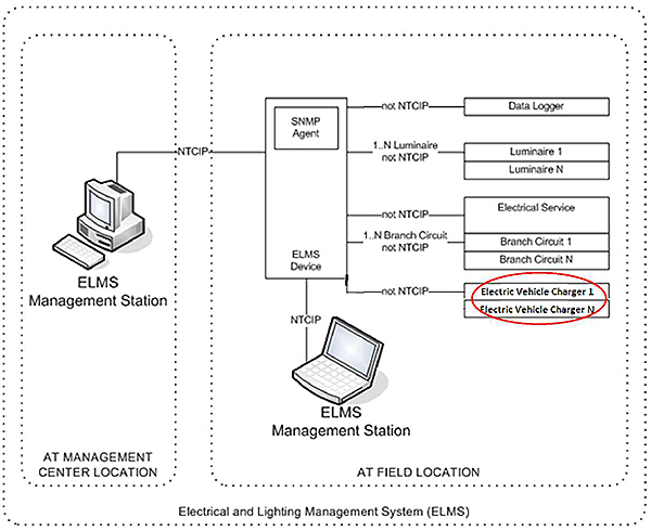
(Extended Text Description: Author's relevant description: The slide includes a graphic of a generic NTCIP 1213 architecture model. On the left is an image of a traffic management center computer workstation, on the right is an image of an NTCIP 1213 contoller with it's functions of data logger, luminaire, electrical service, branch circuit and electric vehicle charger, which is circled in red.)
Slide 22:
Components of the Standard
NTCIP Family of Standards
A family of standards for the ITS industry:
- Information profile standards are called "objects"
- Objects are aggregated in a data table known as a Management Information Base (MIB)
- Underlying communications standards are called "protocols"
- NTCIP 1213 is an Information Content Standard

Slide 23:
Components of the Standard
What Is NTCIP 1213?
- Standardizes the communications interface
- Specifies the interface between the ELMS systems in the field and the host system
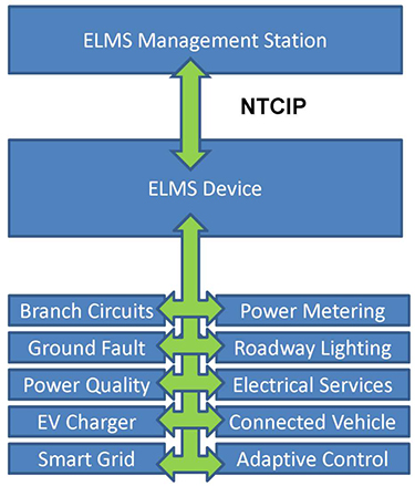
(Extended Text Description: Author's relevant description: This slide describes physical architecture of a basic ELMS system. The slide includes a graphic of a NTCIP 1213 logical communications connections. On the top is a blue block of a traffic management center computer workstation, on the right is an image of an NTCIP 1213 controller with it's functions of data logger, luminaire, electrical service, branch circuit and electric vehicle charger. A green arrow describes the NTCIP 1213 communications between the traffic management center computer workstation and the NTCIP 1213 controller. Other green arrows connect the remaining boxes - these describe non-NTCIP 1213 communications protocols.)
Slide 24:
Components of the Standard
History of the ELMS NTCIP 1213 Standard
- NTCIP 1213 v01.03. February 2004 - Accepted as a User Comment Draft
- NTCIP 1213 v02.19. December 2005 - Accepted v02.19b as a Recommended Standard
- NTCIP 1213 v02.20. February 2011 - Published
- NTCIP 1213 v03 approved by NTCIP JC in May 2016

Slide 25:

Slide 26:
Question
Which of the following statements is true?
Answer Choices
- NTCIP 1213 is an Information Content standard
- NTCIP 1213 is an Application Level standard
- NTCIP 1213 is a Transport Level standard
- NTCIP 1213 is a Plant Level standard
Slide 27:
Review of Answers
 a) NTCIP 1213 is an Information Content standard
Correct, because NTCIP 1213 addresses the Information Level of interoperability.
 b) NTCIP 1213 is an Application Level standard
Incorrect, because NTCIP 1213 does not address the Application Level.
 c) NTCIP 1213 is a Transport Level standard
Incorrect, because NTCIP 1213 does not address the Transport Level.
 d) NTCIP 1213 is a Plant Level standard
Incorrect, because NTCIP 1213 does not address the Plant Level.
Slide 28:
Components of the Standard
Major Benefits of ELMS NTCIP 1213
-
Defines user needs supported by the standard, for example:
- Monitor the Status of the ELMS Luminaire Switch Status Message
-
Defines functional requirements supported by the ELMS standard, for example:
- Monitor the ELMS Luminaire Current Status Message
- Requirements are traced to the user need "monitor the status of the ELMS message"
Slide 29:
Components of the Standard
Advantages of ELMS NTCIP 1213
Enables solutions that are:
- Easier to use
- Easier to specify
- Easier to test

Slide 30:
Components of the Standard
Advantages of SEP and ELMS NTCIP 1213
- Supports off-the-shelf interoperability
- Based on the requirements, the standard specifies the design, ensuring consistency between implementations
- Provides standardized user needs, requirements, and design content to fully support project engineering activities using the Systems Engineering Process (SEP)

Slide 31:
Components of the Standard
ELMS NTCIP 1213 and the SE Life Cycle
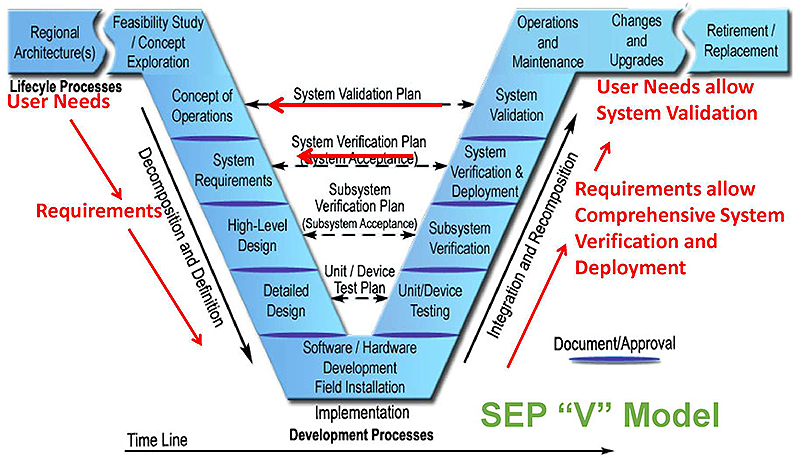
(Extended Text Description: Author's relevant description: On this slide is the standard VEE project workflow model, which represents the Systems Engineering process model. A black timeline is across the bottom of the slide, describing an increasing time variable as the user progresses from left to right across the screen. Located near the blue vee are four statements representing sequential steps of the process. These are; 1. user needs, 2. requirements, 3. Comprehensive system verification and deployment, and 4. System validation.)
Slide 32:

Slide 33:
Question
Which of the following is not an advantage of using the systems engineering process for the ELMS NTCIP 1213 standard?
Answer Choices
- Supports interoperability
- Allows multiple designs for each requirement
- Allows clear development of test procedures based on the requirements selected
- Determines what user needs are supported
Slide 34:
Review of Answers
 a) Supports interoperability
True. NTCIP 1213 SEP process supports the Information Level of interoperability
 b) Allows multiple designs for each requirement
False. NTCIP 1213 does define a unique design for each requirement
 c) Allows clear development of test procedures based on the requirements selected
True. NTCIP 1213 describes clear test procedures
 d) Determines what user needs are supported
True. NTCIP 1213 determines the user needs to be supported
Slide 35:
Learning Objectives
- Understand the structure of the NTCIP 1213 v03 Standard for Electrical and Lighting Management Systems (ELMS)
- Identify specific ELMS user needs
Slide 36:
Learning Objective 2
Identify Specific ELMS User Needs
Slide 37:

Slide 38:
What Are You Trying to Do as ELMS?
An Actual ELMS Case Study - Minneapolis, MN
User Needs
During a downtown reconstruction project, these user needs were identified:
- Lighting system attributes must be monitored
- Ground fault conditions must be communicated in near real-time
- Selected lighting fixtures must be turned off during nonpeak periods
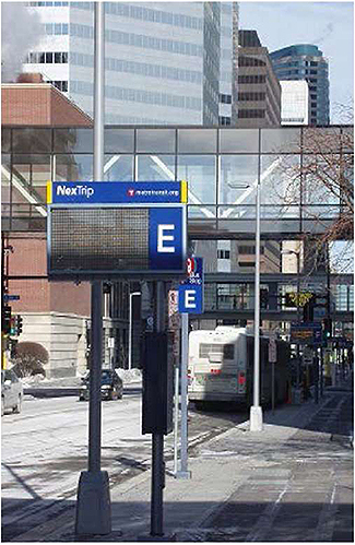
Image © 2017 Jim Frazer

Slide 39:
What Are You Trying to Do as ELMS?
ELMS Case Study - Minneapolis, MN
Results
- Roadway lighting system attributes are monitored
- Ground fault conditions are communicated in near real-time
- Selected lighting fixtures are turned off during nonpeak periods
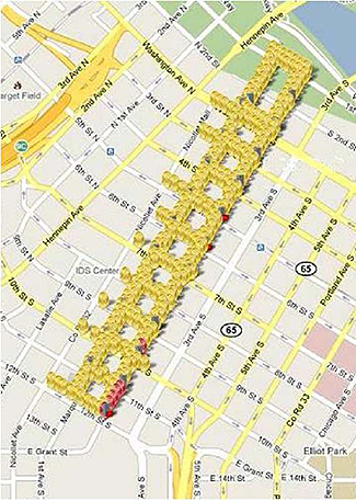
Image © 2016 Gridaptive Technologies
Slide 40:
What Are You Trying to Do as ELMS?
ELMS Case Study - Miami-Dade County, FL
User Needs
Due to severe and fatal injuries of people and animals, these user needs were recognized:
- Ground fault conditions must be communicated in near real-time
- Data must be logged
- Reports of alarms must be generated

Image © 2017 Jim Frazer

Slide 41:
What Are You Trying to Do as ELMS?
ELMS Case Study - Miami-Dade County, FL
Results
- Ground fault conditions are communicated in near real-time
- Data are logged
- Reports of alarms are generated

Image © 2017 Jim Frazer

Slide 42:
What Are You Trying to Do as ELMS?
ELMS Case Study - Route 520 WSDOT
User Needs
During the Route 520 tunnel and bridge project from Seattle to Bellevue, these user needs were identified:
- Energy use must be controlled
- Power outages must be communicated in near real-time
- Adaptive control of lighting based on ambient light levels must be deployed

Image © 2012 Gridaptive Technologies

Slide 43:
What Are You Trying to Do as ELMS?
ELMS Case Study - Washington State DOT
Results
- Energy use is controlled
- Power outages are communicated in near real-time
- Adaptive control of lighting based on ambient light levels is deployed
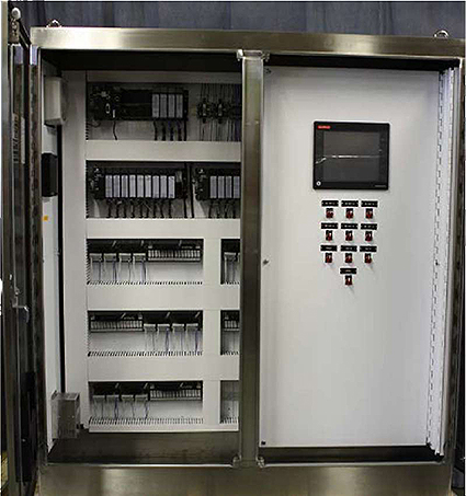
Image © 2012 Gridaptive Techfflogies

Slide 44:
What Are You Trying to Do as ELMS?
ELMS NTCIP 1213 Concept of Operations What is the Concept of Operations?
- Focus is on a system and its users
- Time frame is the life cycle of the system
- Defines the user needs supported by the standard
- Provides an operational context for the system
Slide 45:
What Are You Trying to Do as ELMS?
Primary Uses of ELMS NTCIP 1213 Systems
ELMS is used for control and monitoring of:
- Roadway lighting, including scheduling and zoning
- Safety: electrical leakage anomalies
- Revenue grade power metering, i.e., "billable" metering
-
Integration with other systems including:
- Vehicle to Grid Infrastructure
- The electrical distribution network (The Smart Grid)
- Electric vehicle charging infrastructure, traffic signal power usage, DMS power usage, etc.
Slide 46:
What Are You Trying to Do as ELMS?
What Is a User Need?
Describes the major capability provided by a system to satisfy an operational need
-
A system should not be procured or built without knowing what it is expected to do, such as:
- Control roadway lighting
- Monitor ground fault conditions
- Monitor electrical power usage
Slide 47:
What Are You Trying to Do as ELMS?
Who and What Can Generate User Needs?
User Needs describe the major capability provided by a system to satisfy an operational need
-
People have User Needs
- Travelers
- TMC Operators
- Maintenance Personnel
- In some contexts, a system may generate User Needs: "the management station may need to modify operational parameters..."
Slide 48:
What Are You Trying to Do as ELMS?
ELMS NTCIP 1213 User Needs
ELMS Problem Statement
- Need to manage generic information (e.g., device ID)
- Need to detect/sense device information from sensors in the field
- Need to control field sensor attributes
- Need to integrate to other ELMS systems, and other communications platforms
Slide 49:
NTCIP 1213 Scope
Simple Architecture
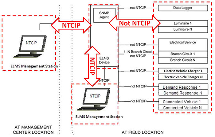
(Extended Text Description: Author's relevant description: This image describes on the left an ELMS management station, in the center an ELMS device, and on the right streetlights, electrical services, branch circuits and connected vehicles. Red arrows describe NTCIP communications only between the management station and the ELMS. Other red arrows show communications that are not NTCIP compliant. This graphic depicts the connections among various ELMS components. The Management Station is connected to the data aggregator ELMS device, and this connection is the subject of the NTCIP standards. The ELMS itself communicates with multiple terminal components, which may include various sensors, including lighting controllers, ground fault interrupters, and revenue grade electric meters.)
Source: Figure 1, Page 9, NTCIP 1213 Standard
Slide 50:
NTCIP 1213 Scope
Alternate Architecture: ELMS within a Luminaire
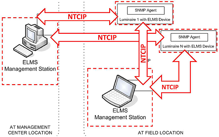
(Extended Text Description: Author's relevant description: This image describes on the left an ELMS management station and on the right streetlights, electrical services, branch circuits and connected vehicles. Red arrows describe NTCIP communications between the management station and the associated filed devices. This graphic depicts the connections among various ELMS components. The Management Station is connected to the data aggregator ELMS device, and this connection is the subject of the NTCIP standards. The ELMS itself communicates with multiple terminal components, which may include various sensors, including lighting controllers, ground fault interrupters, and revenue grade electric meters.)
Source: Figure 1, Page 9, NTCIP 1213 Standard
Slide 51:
NTCIP 1213 Scope
Alternate Architectures - Logical Zoning
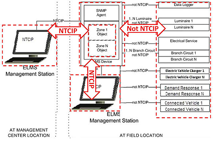
(Extended Text Description: Author's relevant description: This image is identical to that of slide 49 except for the inclusion of a square box in the center labeled "zones 1 through N". This describes the zone function where many terminal devices may be switched by one input.)
Slide 52:
What Are You Trying to Do as ELMS?
ELMS NTCIP 1213 User Needs in Detail
- Section 2.5 describes the major user needs that are related to the definition of the interface between the management station and an ELMS field device
- The user needs are considered to be the "high level" capabilities for NTCIP 1213 v03, and form the basis for defining the detailed functional requirements of the interface
Slide 53:
What Are You Trying to Do as ELMS?
ELMS NTCIP 1213 User Needs in Detail The user needs are organized as follows:
- Operational—defining the basic modes of operation for communication between the management station and field devices
- Features—describing essential data communication functions and message elements to be supported by the interface
Slide 54:
What Are You Trying to Do as ELMS?
ELMS NTCIP 1213 Operational User Needs Provide Live Data (mandatory)
2.5.1.1 Provide Live Data
One operational environment allows the management system to monitor and control the device by issuing requests (e.g., requests to access information, alter information, or control the device). In this environment, the device responds to requests from the management station immediately (e.g., through the provision of live data, success/failure notice of information alteration, or success/failure of the command).
Slide 55:
What Are You Trying to Do as ELMS?
ELMS NTCIP 1213 Operational User Needs
Provide Off-Line Logged Data
2.5.1.2 Provide Off-Line Log Data
Some operational environments do not have always-on connections (e.g., dial-up links). In such environments, a transportation system operator may wish to define conditions under which data are placed into a log, which can then be uploaded at a later time. For example, the operator may wish to manage the ELMS device so that it autonomously maintains a log of whenever a specific luminaire is tufli ed on or off.
Slide 56:
ELMS NTCIP 1213 Features
Relate to the informational needs of the users -control, monitor, and manage:
- Electrical power, metering
- Electrical safety/ground faults
- Electric vehicle charging
- Smart Grid demand management operations
- Connected vehicle driven adaptive lighting

Slide 57:
ELMS NTCIP 1213 Features
Manage Roadway Lighting
Managing Roadway Lighting includes several subneeds:
- Implement Lighting Plan Based on Ambient Light Level
- Implement Lighting Plan Based on Time Base Schedule
- Create Zone
- Configure Zone
Slide 58:
ELMS NTCIP 1213 Features
Manage Roadway Lighting
Managing Roadway Lighting includes several subneeds:
- Configure Schedule
- Apply Schedule to Zone
- Configure Roadway Lighting Dim Level
Slide 59:
ELMS NTCIP 1213 Features
Manage Roadway Lighting
Managing Roadway Lighting also includes luminaire subneeds:
- Configuration of Luminaire Switch State Logging
- Configuration of Luminaire Lamp Condition Logging
- Configuration of Luminaire Burn Condition Logging
- Configuration of Luminaire Pole Condition Logging
Slide 60:
ELMS NTCIP 1213 Features
Manage Roadway Lighting
Managing Roadway Lighting also includes luminaire subneeds:
- Configuration of Luminaire Switch State
- Configuration of Luminaire Identification
- Configuration of Luminaire Dim Level
- Control of Luminaire
Slide 61:
ELMS NTCIP 1213 Features
Manage Electrical Power
Managing Electrical Power includes several subneeds:
- Configure and Monitor Power Meter Switch State
- Configure and Monitor Power Meter Switch State Logging
- Configure and Monitor Power Meter Condition Logging
- Configure and Monitor Power Meter Periodic Measurement Logging
Slide 62:
ELMS NTCIP 1213 Features
Manage Electrical Safety
Managing Electrical Safety includes several subneeds:
- Configure and Monitor Ground Fault Switch State Logging
- Configure and Monitor Periodic Ground Fault Measurement Logging
- Configure and Monitor Electrical Service
Slide 63:
ELMS NTCIP 1213 Features
Manage Electrical Safety
Managing Electrical Safety includes several additional subneeds:
- Configure and Monitor Circuit
- Monitor Circuit Breaker
- Monitor Arc Fault Status
Slide 64:
ELMS NTCIP 1213 Features
Manage Electric Vehicle (EV) Charging
A management station may need to retrieve information from the ELMS device, such as:
- Electric Vehicle Charger Ground Fault Current Status
- Electric Vehicle Charger Charge Current
- Electric Vehicle Charger Proximity Resistance
- Electric Vehicle Charger Temperature
- Electric Vehicle Charger Activation
- Electric Vehicle Charger Operational Status
Slide 65:
ELMS NTCIP 1213 Features
Manage Smart Grid Demand Management
A management station may need to retrieve information from the ELMS device, such as
- Electricity Price
- Energy Price
- Demand Charge
- Bid Price
- Bid Load
- Bid Energy
- Load Dispatch
- Load Control Capacity
- Load Control Offset
- Load Control Setpoints
- Load Control Percent Offset
Slide 66:
ELMS NTCIP 1213 Features
Manage Connected Vehicle Support
A management station may need to configure objects within the ELMS device, such as:
- Connected Vehicle Speed Setpoint
- Connected Vehicle Direction Setpoint
- Connected Vehicle Location Setpoint
- Connected Vehicle Ambient Light Level Setpoint
- Connected Vehicle Headlight Status Setpoint
- Connected Vehicle Road Friction Setpoint
Slide 67:

Slide 68:
Question
Which of the following user needs cannot be satisfied by an ELMS system?
Answer Choices
- Need to inform TMC manager of electrical leakage
- Need to control traffic flow at an intersection
- Need to inform TMC manager of energy usage
- Need to control lighting levels by dimming
Slide 69:
Review of Answers
 a) Need to inform TMC manager of electrical leakage
Incorrect. NTCIP 1213 supports the communications of electrical leakage information
 b) Need to control traffic flow at an intersection
Correct. NTCIP 1213 does not support traffic flow
 c) Need to inform TMC manager of energy usage
Incorrect. NTCIP 1213 supports the communications of energy usage information
 d) Need to control lighting levels by dimming.
Incorrect. NTCIP 1213 supports the communications of dimming information
Slide 70:
Learning Objectives
- Understand the structure of the NTCIP 1213 v03 Standard for Electrical and Lighting Management Systems (ELMS)
- Identify specific ELMS user needs
- Use the Protocol Requirements List (PRL) to select the user needs and trace them to requirements
Slide 71:
Learning Objective 3
Use the Protocol Requirements List (PRL) to select the user needs and trace them to requirements
Slide 72:
Requirements to Be Implemented in a Project-Specific Implementation
PRL as a Tool
- Understand the parts of the PRL
- Use the PRL as a tool for project-specific implementations
- Reduce the risk of failure

Slide 73:
Requirements to Be Implemented in a Project-Specific Implementation
ELMS NTCIP 1213 Functional Requirements
Section 3 of the ELMS standard defines the requirements based on the user needs identified in Section 2, and the interrelationship of user needs and functional requirements.
- Protocol Requirements List (PRL)
- Operational environment requirements
- Functional requirements
- Supplemental requirements

Slide 74:
Requirements to Be Implemented in a Project-Specific Implementation
Purpose of the ELMS Protocol Requirements List The PRL's purpose is:
- To be a table that maps the user needs to the requirements
- Must be part of the agency's specification
- References the standard to define the communication interface
- Designed to help define what you want the interface to do
- Used to identify what requirements will be selected to address a specific set of user needs.

Slide 75:
Requirements to Be Implemented in a Project-Specific Implementation
Purpose of the ELMS Protocol Requirements List
3.3.3 Protocol Requirements List (PRL) Table
Protocol Requirements List (PRL) Table
| User Need ID | User Need | FRID | Functional Requirement | Conformance | Support | Additional Specifications |
|---|---|---|---|---|---|---|
| 2.5.1 | Operational User Needs | M | Yes | |||
| 2.5.1.1 | Provide Live Data | M | Yes | |||
| 35.1.1 | Retrieve Data | M | Yes | |||
| 35.1.2 | Deliver Data | M | Yes | |||
| 3.5.1.3 | Data Retrieval and Data | M | Yes | |||
| Deli very Action Performance | ||||||
| 3.5.1.4 | Live Data ResponseTime | M | Yes | |||
| 2.5.1 .2 | Provide Off-Line Log Data | O | Yes / No | |||
| 3.5.2.1 | Retrieve Configuration of Logging Service | M | Yes | |||
| 3.5.2.2 | Configure Logging Service | M | Yes | |||
| 3.5.2.2.1 | Configure Number of Events in Event Log | M | Yes / No | The ELMS device shall support at least _____ (1 ..255) events. | ||
| 3.5.2.2.2 | Configure Number of Event Classes | M | Yes / No | The ELMS device shall support at least _____ (1 ..255) classes. | ||
| 3.5.2.2.3 | Configure Number of Event Types | M | Yes / No | The ELMS device shall support at least _____ (1 ..255) event types. | ||
| 35.2.3 | Retrieve Logged Data | |||||
| 3 5 2.4 | Clear Log | M | Yes | |||
| 3.5.2.5 | Retrieve Capabilities of Event Logging Services | M | Yes | |||
| 3.5.2.6 | Retrieve Number of Events Currently Logged | M | Yes | |||
| 3.5.2.7 | Set Time | M | Yes | |||

Slide 76:
Requirements to Be Implemented in a Project-Specific Implementation
ELMS User Needs in the PRL
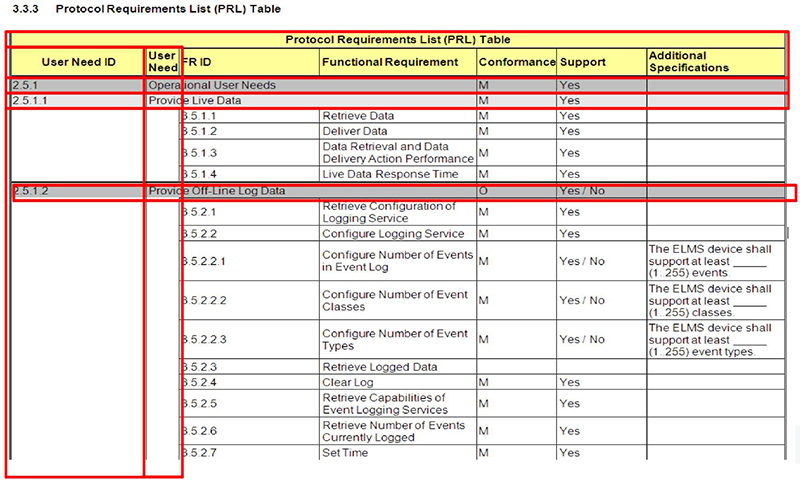
(Extended Text Description: This slide contains the exact same table as slide 75 - 3.3.3 Protocol Requirements List (PRL) Table - but highlights the first two columns of the PRL which is the user need number and textual description.)

Slide 77:
Requirements to Be Implemented in a Project-Specific Implementation
ELMS Functional Requirements in the PRL

(Extended Text Description: This slide contains the exact same table as slide 75 - 3.3.3 Protocol Requirements List (PRL) Table - but highlights columns three and four of the PRL which is the functional requirement number and textual description.)

Slide 78:
Requirements to Be Implemented in a Project-Specific Implementation
ELMS Conformance in the PRL
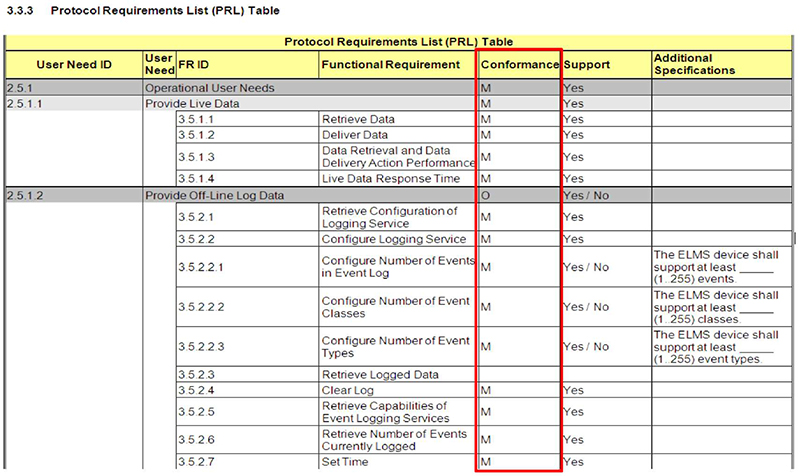
(Extended Text Description: This slide contains the exact same table as slide 75 - 3.3.3 Protocol Requirements List (PRL) Table - but highlights column five of the PRL which is entitled "conformance".)

Slide 79:
Requirements to Be Implemented in a Project-Specific Implementation
ELMS Project Requirements in the PRL
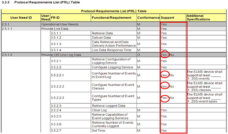
(Extended Text Description: This slide contains the exact same table as slide 75 - 3.3.3 Protocol Requirements List (PRL) Table - but highlights column six of the PRL which is entitled "support" and also shows "Yes" circled in column Support on rows 2.5.1.2, 3.5.2.2.1, 3.5.2.2.2, and 3.5.2.2.3.)

Slide 80:
Requirements to Be Implemented in a Project-Specific Implementation
Other User Needs Not in the PRL
Other Operational Needs:
User Needs Not Supported by NTCIP 1213
- The standard, like the entire suite of NTCIP protocols, allows for extensions
- Proprietary extensions are not desired (interoperability problems), but are sometimes necessary
- Extensions might become part of a future version of the standard
- The standard supports interoperability for all contained
Slide 81:
Checklist to Reduce the Risk of Failure to Conform to NTCIP 1213 v03
Agency Use of the ELMS PRL
The ELMS PRL can be used by:
- A user or agency specification writer to indicate which requirements are to be implemented in a project-specific implementation
- The protocol implementer, as a checklist to reduce the risk of failure to conform to NTCIP 1213

Slide 82:
Checklist to Reduce the Risk of Failure to Conform to NTCIP 1213 v03
Supplier and User Use of the ELMS PRL
The ELMS PRL can also be used by:
- The supplier and user, as a detailed indication of the capabilities of the implementation
- The user, as a basis for initially checking potential interoperability with another implementation

Slide 83:

Slide 84:
Question
Which of the following is a true statement? Answer Choices
- ELMS User Needs do not describe what features the device needs to support and why
- ELMS Functional Requirements are not specifications
- Within the ELMS PRL, the relationships between User Needs and Functional Requirements are not standardized
- The ELMS PRL promotes Interoperability
Slide 85:
Review of Answers
 a) User Needs do not describe what features the device needs to support and why
Incorrect. User Needs do describe supported features.
 b) Functional Requirements are not specifications
Incorrect. Functional Requirements do not support specifications.
 c) Within the PRL, the relationships between User Needs and Functional Requirements are not standardized
Incorrect. Relationships between User Needs and Functional Requirements are standardized.
 d) The PRL promotes Interoperability
Correct. The PRL does support Interoperabiltib.
Slide 86:
Capabilities of the Implementation
Selecting User Needs through the PRL
Using the ELMS User Need ID number 2.5.2.2.2, the corresponding text allows determination if the User Need "Control Electrical Service" is desired in your system.

(Extended Text Description: This slide contains a table with the following content:
| User Need ID | User Need | FR ID | Functional Requirement | Conformance | Support | Additional Specifications |
|---|---|---|---|---|---|---|
| 2.5.2.2.2 | Control Electrical Service | O | Yes / No | |||
| 3.5.5.2.1 | Control Electrical Service by Permanent/Continuous Override | M | Yes | |||
| 3.5.5.2.2 | Control Electrical Service by Transitory Override | O | Yes / No | |||
| 3.5.5.2.3 | Control Electrical Service by Timed Override | O | Yes / No | |||
| 3.5.5.2.4 | Control Electrical Service in Stagger Mode | O | Yes / No | |||
| 3.5.5.2.5 | Control Electrical Service by Photocell | O | Yes / No | |||
| 3.5.5.2.6 | Control Electrical Service by Adaptive Means | O | Yes / No | |||
The word "Yes" in column Support is circled in red on the 2nd, 4th, 6th and 7th rows. The word "No" is circled on the 5th and 8th rows.)

Slide 87:
Capabilities of the Implementation
Selecting User Needs through the PRL
ELMS User Need 2.5.2.2.2 "Control Electrical Service" is defined in the ELMS standard as:
Control Electrical Service
A management station may need to control an electrical service directly or by enabling/disabling the staggered operation for branch circuits served by the electrical service. A management station may need to control the electrical service to allow or disallow the schedule control by one of four states:
- Continuous control
- Transitory control
- Timed control
- Adaptive control

Slide 88:
Capabilities of the Implementation
ELMS PRL and Conformance
Conformance Mandatory vs. Optional
- Examine the "Conformance" column
- Conformance - Identifies if the user need (or requirement) is mandatory or optional
| User Need ID | User Need | FR ID | Functional Requirement | Conformance | Support | Additional Specifications |
|---|---|---|---|---|---|---|
| 2.5.2.2.2 | Control Electrical Service | O | Yes / No | |||
| 3.5.5.2.1 | Control Electrical Service by Permanent/Continuous Override | M | Yes | |||
| 3.5.5.2.2 | Control Electrical Service by Transitory Override | O | Yes / No | |||
| 3.5.5.2.3 | Control Electrical Service by Timed Override | O | Yes / No | |||
| 3.5.5.2.4 | Control Electrical Service in Stagger Mode | O | Yes / No | |||
| 3.5.5.2.5 | Control Electrical Service by Photocell | O | Yes / No | |||
| 3.5.5.2.6 | Control Electrical Service by Adaptive Means | O | Yes / No | |||
Slide 89:
Capabilities of the Implementation
ELMS PRL and Conformance
Conformance Mandatory vs. Optional
- Conformance - Identifies if the user need (or requirement) is mandatory or optional
- Thus, if User Need 2.5.2.2.2 "Control Electrical Service" is required, 3.5.5.2.1 is mandatory, others are optional
| User Need ID | User Need | FR ID | Functional Requirement | Conformance | Support | Additional Specifications |
|---|---|---|---|---|---|---|
| 2.5.2.2.2 | Control Electrical Service | O | Yes / No | |||
| 3.5.5.2.1 | Control Electrical Service by Permanent/Continuous Override | M | Yes | |||
| 3.5.5.2.2 | Control Electrical Service by Transitory Override | O | Yes / No | |||
| 3.5.5.2.3 | Control Electrical Service by Timed Override | O | Yes/ No | |||
| 3.5.5.2.4 | Control Electrical Service in Stagger Mode | O | Yes / No | |||
| 3.5.5.2.5 | Control Electrical Service by Photocell | O | Yes / No | |||
| 3.5.5.2.6 | Control Electrical Service by Adaptive Means | O | Yes / No | |||
Slide 90:

Slide 91:
Question
Which of the following descriptions of the PRL is a false statement?
Answer Choices
- Options for Conformance are Mandatory or Optional
- Options for Project Requirements are Yes or No
- Optional User Needs are dependent on Project Requirements
- Optional Functional Requirements are not dependent on Project Requirements
Slide 92:
Review of Answers
 a) Options for Conformance are Mandatory or Optional
True statement. The only valid entries for Conformance are Mandatory and Optional.
 b) Options for Project Requirements are Yes or No
True statement. The only valid entries for Project Requirements are Yes and No.
 c) Optional User Needs are dependent on Project Requirements
True statement. Selection of Project Requirements drives the inclusion/exclusion of optional User Needs.
 d) Optional Functional Requirements are not dependent on Project Requirements
False. Selection of Project Requirements drives the inclusion/exclusion of optional FRs.
Slide 93:
Capabilities of the Implementation
ELMS User Needs Hierarchical Relationship
- User Need 2.5.1.2 is Optional. Thus, if the project definition requires this user need, then
- Dependent Requirements are Mandatory
| 2.5.1.2 | Provide Off-Line Log Data | O | Yes / No | |||
| 3.5.2.1 | Retrieve Configuration of Logging Service | M | Yes | |||
| 3.5.2.2 | Configure Logging Service | M | Yes | |||
| 3.5.2.2.1 | Configure Number of Events in Event Log | M | Yes / No | The ELMS device shall support at least _____ (1. 255) events. | ||
| 3.5.2.2.2 | Configure Number of Event Classes | M | Yes / No | The ELMS device shall support at least _____ (1 ..255) classes. | ||
| 3.5.2.2.3 | Configure Number of Event Types | M | Yes / No | The ELMS device shall support at least _____ (1. 255) event types. | ||
| 3.5.2.3 | Retrieve Logged Data | |||||
| 3.5.2.4 | Clear Log | M | Yes | |||
| 3.5.2.5 | Retrieve Capabilities of Event Logging Services | M | Yes | |||
| 3.5.2.6 | Retrieve Number of Events Currently Logged | M | Yes | |||
| 3 5.2.7 | Set Time | M | Yes | |||

Slide 94:
Capabilities of the Implementation
ELMS PRL User Needs:
Project Requirements Relationship
Agency/Specifier to circle Yes or No to indicate the agency's user needs for the proposed implementation

(Extended Text Description: This slide contains a table with the following content:
| 2.5.2.1.21 | Configure ELMS Device for Adaptive Operation | O | Yes / No | ||
| 3.5.4.23 | Configure ELMS Device for Adaptive Operation | O | Yes / No | ||
| 3.5.4.23.1 | Configure Connected Vehicle Speed Setpoint | O | Yes / No | ||
| 3.5.4.23.2 | Configure Connected Vehicle Direction Setpoint | O | Yes / No | ||
| 3.5.4.23.3 | Configure Connected Vehicle Location Setpoint | O | Yes / No | ||
| 3.5.4.23.4 | Configure Connected Vehicle Ambient Light Level Setpoint | O | Yes / No | ||
| 3.5.4.23.5 | Configure Connected Vehicle Headlight Status Setpoint | O | Yes / No | ||
| 3.5.4.23.6 | Configure Connected Vehicle Road Friction Setpoint | O | Yes / No | ||
The word "Yes" in column Yes/No is circled in red on the 1st, 2nd, 3rd, 5th, 7th and 8th rows. The word "No" is circled on the 4th and 6th rows.)

Slide 95:
Capabilities of the Implementation
Importance of the ELMS PRL's User Needs and Functional Requirements Relationship
- User Needs describe required features
- Functional Requirements refine the user needs into detailed specifications
- Within the PRL, the relationships between User Needs and Functional Requirements are standardized
- Use of the PRL's User Needs and dependent Functional Requirements promotes interoperability

Slide 96:
Capabilities of the Implementation
ELMS PRL's User Needs/Functional Requirements Relationship in Detail
- Functional Requirement Identifier (FR ID) -Section Number of the Functional Requirement
- Functional Requirement (FR) -
Title (description of the functional requirement)

(Extended Text Description: This slide image is again a subset of the PRL with the following table:
| User Need ID | User Need | FR ID | Functional Requirement | Conformance | Support | Additional Specifications |
|---|---|---|---|---|---|---|
| 2.5.2.1.22 | Retrieve ELMS Device Adaptive Operation Configuration | O | Yes / No | |||
| 3.5.4.24 | Retrieve ELMS Device Adaptive Operation Configuration | O | Yes / No | |||
| 3.5.4.24.1 | Retrieve Connected Vehicle Speed Setpoint | O | ||||
| 3.5.4.24.2 | Retrieve Connected Vehicle Direction Setpoint | O | ||||
| 3.5.4.24.3 | Retrieve Connected Vehicle Location Setpoint | O | ||||
| 3.5.4.24.4 | Retrieve Connected Vehicle Ambient Light Level Setpoint | O | ||||
| 3.5.4.24.5 | Retrieve Connected Vehicle Headlight Status Setpoint | O | ||||
The 3rd and 4th columns are outlined in red.)

Slide 97:
Capabilities of the Implementation
ELMS PRL's User Needs/Functional Requirements Relationship in Detail
- Requirements associated with a User Need are found under that User Need
- Each user need will have at least one requirement associated with it
- Each requirement in the standard is associated with at least one user need
- Result: The standard has no unnecessary requirement, and all user needs are satisfied by at least one requirement

Slide 98:
Capabilities of the Implementation
ELMS PRL's User Needs/Functional Requirements Relationship in Detail
Mandatory vs. Optional
- A "mandatory" requirement is only mandatory if an associated user need is selected
- If an optional User Need is not selected, its associated requirements are not necessary, unless they are required by another user need selection
- Example: "3.5.4.4.4 - Configure Devices in Zone for Light Activated Operation"

Slide 99:
Capabilities of the Implementation
ELMS PRL's User Needs/Functional Requirements Relationship in Detail
Additional Project Requirements Column
Used to provide further details about the implementation
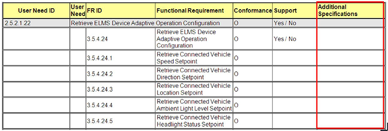
(Extended Text Description: This slide image is again a subset of the PRL, and contains the same table as slide 96. The difference is that in this slide, the last column - Additional Specifications - is outlined in red.)

Slide 100:

Slide 101:
Question
Which of the following is a false statement? Answer Choices
- User Needs describe what features the device needs to support
- Functional Requirements refine the user needs into specifications
- Relationships between User Needs and Functional Requirements are standardized
- The ELMS PRL does not promote interoperability
Slide 102:
Review of Answers
 a) User Needs describe what features the device needs to support
True statement. User Needs describe what features are required.
 b) Functional Requirements refine the user needs into specifications
True statement. Functional Requirements do refine user needs into detailed, measurable specifications.
 c) Relationships between User Needs and Functional Requirements are standardized
True statement. The PRL defines standardized relationships.
 d) The PRL does not promote interoperability
False. The PRL does promote interoperabilw
Slide 103:
Ensure Interoperability with Another Implementation: Existing ELMS System, Smart Grid, EV Charging, and Connected Vehicle Systems
Using the ELMS PRL to Check Interoperability
Use of the ELMS PRL supports interoperability of selected attributes with:
- The ITS Management Center
- Other ELMS systems, on site or remote
- Smart Grid systems for automated demand management
- Connected vehicle and connected pedestrians for true adaptive roadway lighting
- Electric vehicle charging stations

Slide 104:
Benefits of PRL
What Does Use of the PRL Achieve?
- Each Requirement has a need
- No Needs are unmet
- Extraneous requirements are avoided.
Slide 105:
Learning Objectives
- Understand the structure of the NTCIP 1213 v03 Standard for Electrical and Lighting Management Systems (ELMS)
- Identify specific ELMS user needs
- Use the Protocol Requirements List (PRL) to select the user needs and trace them to requirements
- Explain how to use the ELMS PRL table for the ELMS specification
Slide 106:
Learning Objective 4
- How to use the PRL table for the ELMS Specification
Slide 107:
User Needs-Requirements Link
Integrating the ELMS PRL into an ELMS Specification
From an agency's perspective:
- A completed PRL must become part of the overall specification
- A completed PRL indicates the requirements for the communications interface
- Agency provides language in the specification that all selected requirements must be implemented as per the standard in order to support off-the-shelf interoperability

Slide 108:
User Needs-Requirements Link
Integrating the ELMS PRL into an ELMS Specification From a vendor's perspective:
- Even if a user need and resulting requirement(s) is not mandatory, a vendor may optionally fulfill the user need and provide the feature
- Vendors can provide a PRL for their standard products to show what user needs they support
Slide 109:
User Needs-Requirements Link
Integrating the ELMS PRL into an ELMS Specification
ELMS Contract Documents:
A completed ELMS PRL is part of the overall project specification, in addition to the hardware and software specifications
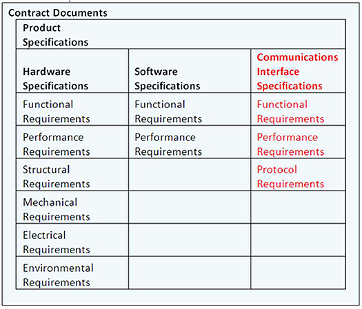
(Extended Text Description: Diagram representing the contract documents organized in a box as follows: The Product Specifications contains Hardware Specifications, Software Specifications, and Communications Interface Specifications origanized into three columns. The Hardware Specifications column contains: Functional Requirements, Performance Requirements, Structural Requirements, Mechanical Requirements, Electrical Requirements, Environmental Requirements. The Software Specifications column contains: Functional Requirements, Performance Requirements. The Communications Interface Specifications column contains: Functional Requirements, Performance Requirements, Protocol Requirements. The Communications Interface Specifications column is highlighted in red.)

Slide 110:
User Needs-Requirements Link
Integrating the ELMS PRL into an ELMS Specification -Conformance vs. Compliance
-
Conformance:
- Meets a specified standard
-
Compliance
- Meets a specification (e.g., for a specific project)

Slide 111:

Slide 112:
Question
Which of the following is a false statement? Answer Choices
- Vendors can provide an ELMS PRL for their standard products to show what user needs they support
- A completed ELMS PRL must become part of the overall specification
- A completed ELMS PRL indicates the requirements for the communications interface
- A completed ELMS PRL describes the entire project
Slide 113:
Review of Answers
 a) Vendors can provide an ELMS PRL for their standard products to show what user needs they support.
True statement. Products can be evaluated for standardization.
 b) A completed ELMS PRL must become part of the overall specification
True statement. Project specifications includes communications, hardware, and software specifications.
 c) A completed ELMS PRL indicates the requirements for the communications interface
True statement. The PRL defines the communications interface.
 d) A completed ELMS PRL describes the entire project specification
False. It only describes the communications interface.
Slide 114:
Module Summary
- Understand the structure of the NTCIP 1213 v03 Standard for Electrical and Lighting Management Systems (ELMS)
- Identify specific ELMS user needs
- Use the Protocol Requirements List (PRL) to select the user needs and trace them to requirements
- Explain how to use the ELMS PRL table for the ELMS specification
Slide 115:
We Have Now Completed A306a in the ELMS Curriculum
 |
Module A306a: Understanding User Needs for Electrical and Lighting Management Systems Based on NTCIP 1213 ELMS Standard v03 |
| Module A306b: Specifying Requirements for Electrical and Lighting Management Systems Based on NTCIP 1213 ELMS Standard v03 | |
| Module T306: Applying Your Test Plan to the Electrical and Lighting Management Systems based on NTCIP 1213 ELMS Standard v03 |
Slide 116:
Next Course Module
Module A306b: Specifying Requirements for Electrical and Lighting Management Systems (ELMS) Based on NTCIP 1213 Standard
Concepts taught in next module (Learning Objectives):
- Review the structure of the NTCIP 1213 v03 Standard
- Use the PRL and then the RTM to specify the standardized structure of requirements
- Include the requirements from the PRL and RTM in the ELMS Communications Interface specification
- Explain conditions and context for extending the standard
Slide 117:
Thank you for completing this module. Feedback
Please use the Feedback link below to provide us with your thoughts and comments about the value of the training.
Thank you!