Module 30 - T321
T321: Applying Your Test Plan to TMDD Standard
HTML of the PowerPoint Presentation
(Note: This document has been converted from a PowerPoint presentation to 508-compliant HTML. The formatting has been adjusted for 508 compliance, but all the original text content is included, plus additional text descriptions for the images, photos and/or diagrams have been provided below.)
Slide 1:
(Extended Text Description: Slide 1: Welcome - Graphic image of introductory slide. A large dark blue rectangle with a wide, light grid pattern at the top half and bands of dark and lighter blue bands below. There is a white square ITS logo box with words "Standards ITS Training" in green and blue on the middle left side. The word "Welcome" in white is to the right of the logo. Under the logo box are the words "RITA Intelligent Transportation Systems Joint Program Office.")
Slide 2:
Welcome

Ken Leonard, Director
ITS Joint Program Office

(Extended Text Description: Intro Slide: Screen capture snapshot of RITA website - for illustration only. Below this image is a link to the current website: https://www.its.dot.gov/pcb - this screen capture snapshot shows an example from the RITA website from April 2013. At the top of the page it shows the RITA logo with the text U.S. Department of Transportation Research and Innovative Technology Administration - Intelligent Transportation Systems Joint Program Office - ITS Professional Capacity Building Program/Advanced ITS Education. Below the main site banner, it shows the main navigation menu with the following items: About, ITS Training, Knowledge Exchange, Technology Transfer, ITS in Academics, and Media Library. Below the main navigation menu, the page shows various content of the website, including a graphic image of professionals seated in a room during a training program. A text overlay has the text Welcome to ITS Professional Capacity Building. Additional content on the page includes a box entitled What's New and sections entitled Available E-Training (free), Free ITS Training and T3 Webinars. Again, this image serves for illustration only. The current website link is: https://www.its.dot.gov/pcb)
(Note: There is additional text attached to this slide that includes the following introductory information from Ken Leonard):
"ITS Standards can make your life easier. Your procurements will go more smoothly and you'll encourage competition, but only if you know how to write them into your specifications and test them. This module is one in a series that covers practical applications for acquiring and testing standards-based ITS systems.
I am Ken Leonard, director of the ITS Joint Program Office for USDOT and I want to welcome you to our newly redesigned ITS standards training program of which this module is a part. We are pleased to be working with our partner, the Institute of Transportation Engineers, to deliver this new approach to training that combines web based modules with instructor interaction to bring the latest in ITS learning to busy professionals like yourself.
This combined approach allows interested professionals to schedule training at your convenience, without the need to travel. After you complete this training, we hope that you will tell colleagues and customers about the latest ITS standards and encourage them to take advantage of the archived version of the webinars.
ITS Standards training is one of the first offerings of our updated Professional Capacity Training Program. Through the PCB program we prepare professionals to adopt proven and emerging ITS technologies that will make surface transportation safer, smarter and greener which improves livability for us all. You can find information on additional modules and training programs on our web site ITS PCB Home
Please help us make even more improvements to our training modules through the evaluation process. We look forward to hearing your comments. Thank you again for participating and we hope you find this module helpful."
Slide 3:

Slide 4:
T321:
Applying Your Test Plan to the TMDD Standard
Slide 5:
Instructor

Patrick Chan, P.E.
Senior Technical Staff
Consensus Systems Technologies (ConSysTec)
Flushing, NY, USA
Slide 6:
Target Audience
- Engineering staff
- Operations and maintenance staff
- System integrators
- Device manufacturers
- Testing contractors
Slide 7:
Recommended Prerequisite(s)
- T101: Introduction to ITS Standards Testing
- T201: How to Write a Test Plan
- T202: Overview of Test Design Specifications, Test Cases, and Test Procedures
- C101: Introduction to the Communications Protocols and Their Uses in ITS Applications
- A321a: Understanding User Needs for Traffic Management Systems Based on TMDD v3.03 Standard
- A321b: Specifying Requirements for Traffic Management Systems Based on TMDD v3.03 Standard
Slide 8:
Curriculum Path (SEP)
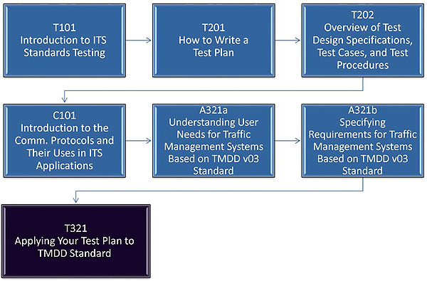
(Extended Text Description: A flowchart showing the recommended curriculum path leading to this module. The first box is module T101: Introduction to ITS Standards Testing. The next module in the curriculum path is T201: How to Write a Test Plan. The third recommended module is T202: Overview of Test Design Specifications, Test Cases, and Test Procedures. The fourth module is C101: Introduction to Communications Protocols and Their Uses in ITS Applications. The fifth module is A321a: Understanding User Needs for Traffic Management Systems Based on TMDD v03 Standard. The sixth module is A321b: Specifying Requirements for Traffic Management Systems Based on TMDD v03 Standard. The final module in the flow chart is this module, T321: Applying Your Test Plan to the TMDD Standard.)
Slide 9:
Learning Objectives
- Describe within the context of a testing life cycle the role of a test plan and the testing to be undertaken.
- Recognize the purpose, structure, and content of a well-written test plan for a TMDD-based system interface.
- Describe the application of a good test plan to a TMDD-based system being procured using a sample TMDD test plan.
Slide 10:
Learning Objectives (cont.)
- Identify the process to write a test plan in the context of the requirements of TMDD that have been selected by the user.
- Analyze how to ensure conformance with the TMDD v3.03 Standard.
- Describe test documentation for TMDD: Test Plan, Test Design Specification, Test Case Specifications, Test Procedure Specifications and Test Reports.
Slide 11:
Learning Objective #1 - Describe within the context of a testing life cycle the role of a test plan and the testing to be undertaken
- Explain why testing is important within the life cycle of a system.
- Identify how to break up (partition) the testing (meaning verification of requirements), and when, during the system development life cycle, requirements are tested.
Slide 12:
Learning Objective #1
Purpose of Testing
Why Test:
- To verify that the system works
- To meet a payment milestone
Why Test - Technically:
- To verify the system interface meets the procurement specification and satisfies the requirements (Was the system built right?)
- To identify errors/bugs so they can be corrected
- To validate that the system interface satisfies the user and operational needs (Did you build the right system?)
Slide 13:
Learning Objective #1
System Life Cycle
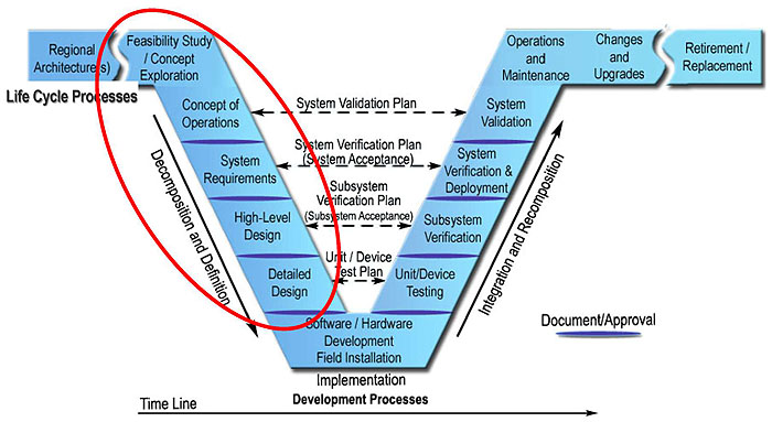
(Extended Text Description: This is a figure depicting the life cycle of a system and the relationships between each process (or step) of a system life cycle. The figure is laid like the letter "V", thus it is called the "VEE" diagram. Time progresses as we move from the left side of the "VEE" to the right side of the "VEE". Starting from the upper left hand corner of the "VEE" and moving right and down, the processes are Regional Architecture(s), Feasibility Study / Concept Exploration, Concept of Operations, System Requirements, High-Level Design, and Detailed Design. These processes on the left side of the "VEE" is part of the Decomposition and Definition step. At the bottom of the "VEE" is the Software / Hardware Development Field Installation Implementation process, which is called the Development Process step. Moving up the right side of the "VEE", the processes are the Unit/Device Testing, Subsystem Verification, System Verification and Deployment, System Validation, Operations and Maintenance, Changes and Upgrades, and finally Retirement/Replacement. These processes on the right side of the "VEE" is called the Integration and Recomposition step. For the completion of each process, starting with the Concept of Operations to the completion of the System Verification and Deployment process, a document is produced or some type of formal approval is expected before continuing onto the next process. Verification or validation is expected between the processes on the left side of the "VEE" and the right side "VEE", and are indicated by dotted lines with arrows on the end between them. There is a dotted line between the Concept of Operations on the left and the System Validation on the right, labeled System Validation Plan. This indicates that testing of the Concept of Operations is performed in the System Validation Plan during the System Validation process. The next dotted line is between the Systems Requirements on the left and System Verification & Deployment on the right, and the line is labeled System Verification Plan, or in parentheses, System Acceptance. The next dotted line is between the High-Level Plan and the Subsystem Verification and it is labeled Subsystem Verification Plan, or in parentheses, Subsystem Acceptance. The last dotted line is between the Detailed Design and the Unit/Device Testing, and it is labeled Unit/Device Test Plan. The discussion for this slide focuses on the left side of the "VEE" diagram, so the left side is circled in red.)
Slide 14:
Learning Objective #1
System Life Cycle
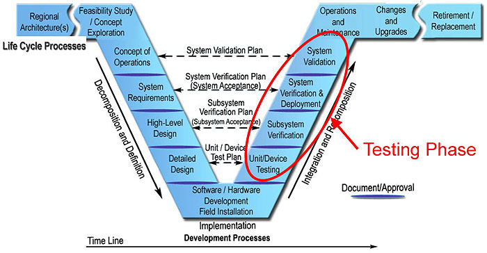
(Extended Text Description: This is the same figure as in Slide 13, depicting the life cycle of a system and the relationships between each process (or step) of a system life cycle, so see Slide 13 for a description. However, the discussion for this slide focuses on the right side of the "VEE" diagram, so the right side is circled in red, with the label Testing Phase.)
Slide 15:
Learning Objective #1
Testing Process
IEEE 829:
-
The testing process provides an objective assessment of the system products through each system's life cycle:
- At the completion of each development iteration
- At installation and go-live
- During operations and maintenance
- During system upgrades
- During system replacement
Slide 16:
Learning Objective #1
Review of Testing

(Extended Text Description: This is a figure showing a snapshot of a portion of the "VEE" diagram, showing the Concept of Operations process on the left side of the "VEE" and the System Validation process on the right side of the "VEE" diagram, with a dotted line labeled System Validation Plan between the two processes.)
Validation
- Validation - e.g., answers the question: Can I operate the system and satisfy all my stakeholder's user needs?
- Validation ensures the requirements and the system are the right solution to the stated problem - i.e., "you built the right system."
-
The system is validated when:
- Approved by the key stakeholders and agencies.
- All the project requirements are fulfilled.
- Corrective actions have been implemented for any anomalies that have been detected.
Slide 17:
Learning Objective #1
Review of Testing (Cont.)
Verification
-
Ongoing process that builds quality into the system through a systematic approach of verification of requirements - i.e., "you built the system right."
- Unit/Device Testing - e.g., test a standalone TMDD interface

(Extended Text Description: This is a figure showing a snapshot of a portion of the "VEE" diagram, showing the Detailed Design process on the left side of the "VEE" and the Unit/Device Testing process on the right side of the "VEE" diagram, with a dotted line labeled Unit/Device Test Plan between the two processes.)
Slide 18:
Learning Objective #1
Review of Testing (Cont.)
Verification
- Subsystem Verification-e.g., tests a TMDD system interface and its immediate environment, typically under laboratory or center environment
- System Verification & Deployment-e.g., Tests the entire TMDD system, including the TMC software

(Extended Text Description: This is a figure showing a snapshot of a portion of the "VEE" diagram, showing the process System Requirements on the left side of the "VEE" and the System Verification & Deployment process on the right side of the "VEE" diagram, with a dotted line labeled System Verification Plan, with System Acceptance in parentheses, between the two processes. The figure also shows the High-Level Design on the left side of the "VEE" and the Subsystem Verification process on the right side of the "VEE" diagram, with a dotted line labeled Subsystem Verification Plan, with Subsystem Acceptance in parentheses, between the two processes.)
Slide 19:

Slide 20:
Learning Objective #1
Which of the following is NOT a reason to perform testing?
Answer Choices
- Develop Concept of Operations
- Verify requirements are fulfilled
- Validate the user needs are satisfied
- Assess a system upgrade versus the existing system
Slide 21:
Learning Objective #1
Review of Answers
 a) Develop Concept of Operations
Correct, ConOps belongs in the definition phase of the system life cycle.
 b) Verify requirements are fulfilled
Incorrect, this is a reason for testing.
 c) Validate the user needs are satisfied
Incorrect, this is a reason for testing.
 d) Assess a system upgrade against the existing system
Incorrect, this is a reason for testing.
Slide 22:
Summary of Learning Objective #1
Describe within the context of a testing life cycle the role of a test plan and the testing to be undertaken
- Explain why testing is important within the life cycle of a system.
- Identify how to break up (partition) the testing (meaning verification of requirements), and when, during the system development life cycle, requirements are tested
Slide 23:
Learning Objective #2 - Recognize the Purpose, Structure, and Content of a Well-Written Test Plan for a TMDD-based System Interface
- Identify the purpose of a test plan
- Describe the components of a test plan and explain the purpose of each component
Slide 24:
Learning Objective #2
What is a Test Plan?
IEEE 829 Defines a Test Plan as:
-
A document describing the scope, approach (technical and management), resources, schedule of intended test activities, and deliverables.
- Identifies the risks and their contingencies
- The document may be a Master Test Plan or a Level Test Plan
- Covered in detail in Module T201 - How to Write a Test Plan
Test Plans are not defined in the TMDD standard
Slide 25:
Learning Objective #2
Test Plans
A Test Plan is a high-level plan that defines:
-
What item is to be tested?
- Identifies the scope of the test plan
- What portions of the TMDD-based system interface (portion of the TMDD standard) you are going to test and in what order?
-
What features are to be tested?
- Identifies the features to be tested
- What TMDD v3.03 requirements will be tested?
Slide 26:
Learning Objective #2
Types of Test Plans
-
There may be a separate Test Plan for each type of testing:
- Unit/Device Test Plan
- Subsystem Verification Plan (System Integration)
- System Verification Plan (System Acceptance)
- System Validation Plan
- Periodic Maintenance
-
Master Test Plan
- Describes how all the test plans work together to verify and validate the system
Slide 27:
Learning Objective #2
Approach to Test Plans
-
What is the overall approach to testing?
- Permit identification of the major testing tasks and estimation of time
- Trace the requirements to be tested
- Identify significant constraints such as item availability, resource availability, and deadlines
-
Answers the questions
- Does the test item conform to the standard?
- Does the system exhibit the functionality defined in the specifications?
Slide 28:
Learning Objective #2
Approach to Test Plans (cont.)
-
What are the pass/fail criteria?
- Identifies the criteria to determine whether each test item has passed or failed testing.
-
What are the suspension criteria and resumption requirements?
- Specifies the criteria to suspend all or a portion of the testing activities.
- Specifies the criteria for regression testing (repeating testing activities) and when testing is resumed.
Slide 29:
Learning Objective #2
Test Environment
-
How is the item to be tested?
- Identifies the test environment (environmental needs) to be used for executing the test plan, such as facilities, hardware, communications, system software, and pre-conditions for testing.
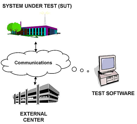
(Extended Text Description: A figure with three graphics. One graphic depicts a management center labeled System Under Test (SUT), a second graphic depicts a different management center labeled External Center, and third graphic depicts a computer, labeled Test Software. Between the three graphics is a cloud labeled Communications. There is a line with arrows on each end between each management center, to depict information exchanges between management centers and the communications cloud. There is also a dotted line between the Test Software and the communications cloud to indicate that the Test Software can "read" the information exchanges in the communications cloud.)
Slide 30:
Learning Objective #2
Test Plan Deliverables
-
What are the test deliverables?
- Test Design Specifications. Specifies the test approach for a feature or combination of features and identifying the associated tests.
- Test Case Specifications. Specifies inputs, predicted results, and a set of execution conditions for a test item.
- Test Procedure Specifications. Specifies a sequence of actions for the execution of a test.
- Test Reports. Summaries the results of the testing activities and results, including any incidents.
Slide 31:
Learning Objective #2
Example Framework for Test Documentation
- A Test Plan may consist of several Test Design Specifications (e.g., unit test, integration test, acceptance test)
- There may be a separate Test Design Specification for each implementation
- Each Test Design Specification may consist of several Test Case Specifications and Test Procedure Specifications
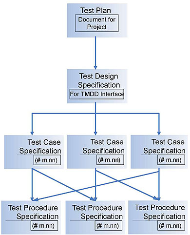
(Extended Text Description: A figure showing a diagram similar to an organization chart. On top is a box labeled Test Plan, with a smaller box inside labeled Document for Project. From this box is a line pointing to another box below it labeled Test Design Specification, with a smaller box inside labeled For TMDD Interface. From this box are three lines pointing to three different boxes in a single row below it, each labeled Test Case Specification. Within each of these three boxes is a smaller box labeled (# m, nn), to indicate multiple Test Case Specifications. Below the row of Test Case Specifications is another row of three boxes, each labeled Test Procedure Specification, and within each box is a smaller box labeled (# m, nn), to indicate multiple Test Procedure Specifications. There are multiple lines pointing from each Test Case Specification to different Test Procedures Specifications.)
Slide 32:
Learning Objective #2
Test Plan - Staff and Resources
-
Who is to test the item?
- Identifies the roles and responsibilities for each person in managing, designing, preparing, executing, and resolving.
-
What staffing and training is needed?
- Specify staffing needs by skills, and identify training options for providing necessary skills.
- Project managers, programmers, test managers, TMC supervisors?
Slide 33:
Learning Objective #2
Test Plan - Schedule, Risk, Approvals
-
When is the testing to take place?
- Identifies the testing milestones, including testing dependencies, submittals, time to perform each task, and testing resources.
-
What are the risks and contingency plans?
- Identifies the high risk assumptions of the test plan and specifies contingency plans for each.
- Who needs to approve the test plans?
Slide 34:

Slide 35:
Learning Objective #2
Which of the following does NOT belong in a well-written test plan?
Answer Choices
- Testing Environment
- Testing Plan Staff Requirements
- Pass/Fail Criteria
- Sequence of Actions to be Performed
Slide 36:
Learning Objective #2
Review of Answers
 a) Testing Environment
Incorrect, the testing environment is defined in a test plan.
 b) Testing Plan Staff Requirements
Incorrect, staffing requirements are defined in a test plan.
 c) Pass/Fail Criteria
Incorrect, the pass/fail criteria is part of a test plan.
 d) Sequence of Actions to be Performed
Correct, the sequence of actions to be performed are part of the Test Procedures Specifications.
Slide 37:
Summary of Learning Objective #2
Recognize the purpose, structure, and content of a well-written test plan for a TMDD-based system interface
- Identify the purpose of a test plan
- Describe the components of a test plan and explain the purpose of each component
Slide 38:
Learning Objective #3 - Describe the application of a good test plan to a TMDD-based system being procured using a sample TMDD test plan
- Describe the structure of the TMDD v3.03 Standard
- Explain what is and is not tested when testing a TMDD-based system
- Review a sample test plan for a TMDD-based system
Slide 39:
Learning Objective #3
Traffic Management Data Dictionary (TMDD)
What is TMDD?
-
TMDD is a communications system interface standard designed primarily for the traffic management domain
- TMDD contains a data dictionary (vocabulary) to exchange incident information, traffic network information, and the monitoring and control of devices operated by a remote center
- TMDD data concepts are also utilized by other ITS applications such as incident management
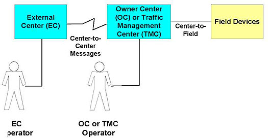
(Extended Text Description: A figure with three boxes showing the interfaces between the External Center (EC), which is box one, the Owner Center (OC) or Traffic Management Center (TMC), which is box two, and Field Devices, which is box three. The External Center and Owner Center (OC) or Traffic Management Center (TMC) are in blue boxes, to indicate centers, while the Field Devices box is yellow, to indicate field devices. There is a line between the two center boxes and is labeled Center-to-Center Messages, and a line between the Owner Center (OC) or Traffic Management Center (TMC) box and the Field Devices box and is labeled Center-to-Field. A graphic of a person labeled EC Operator is shown with a line to the External Center (EC) box and a graphic of a person labeled OC or TMC Operator is shown with a line to the Owner Center (OC) or Traffic Management Center (TMC) box.)
Slide 40:
Learning Objective #3
Content of the TMDD
Recall Structure of the Standard
- Defines user needs
- Defines requirements
-
Defines a single design for each requirement supported by the standard
- Supports interoperability between a traffic management center and other centers (e.g., other traffic management, transit, public safety, maintenance, planning organizations, etc.)
Slide 41:
Learning Objective #3
Content of the TMDD (cont.)
-
NRTM (Needs to Requirements Matrix)
- Traces a user need and the requirements that satisfies the user need
- A completed NRTM indicates what requirements (features) have been selected for the procurement specification
-
RTM (Requirements Traceability Matrix)
- Defines the design (dialogs, messages, and data elements) that must be used to fulfill a requirement.
Slide 42:
Learning Objective #3
Test Plan for a TMDD-based System
What are we testing?
- Compliance with the procurement specification - Does the TMDD-based system fulfill all the requirements (shall statements) in the procurement specification?
- Conformance with the TMDD Standard - Does the TMDD-based system fulfill the mandatory requirements identified by the standard. The TMDD-based system must also fulfill other specified (user-selected) requirements of TMDD and the standards it references.
- Conformance is NOT compliance!
Slide 43:
Learning Objective #3
Testing a TMDD-based System (cont.)
What is being tested?
-
Testing that the proper protocols are being used?
- E.g., NTCIP 2304 or NTCIP 2306
-
Testing that the data exchanges occur as defined by the standard?
- Sequence of request-response messages
- Sequence of subscription and publication messages
- Correct handling of error messages
- Correct structure of the TMDD messages
- Correct data content is being exchanged
Slide 44:
Learning Objective #3
Testing a TMDD-based System (cont.)
T321 module does not directly address:
-
How the data is used in the implementation's environment
- It only verifies that the design content (interface) fulfills requirements so the operational needs are satisfied
-
The operation(s) the implementation is attempting to support via the interface
- E.g., this test plan does not consider how a device is monitored or controlled, how an operator views event information, or how a device queue or plan library is managed
Slide 45:
Learning Objective #3
Example Test Plan for a TMDD-based System
Introduction and Test Items
- Test Plan Identifier: TP-TMDD-xxxx
-
Introduction:
- Purpose: Verify center-to-center interface between Agency X and Agency Y complies with Interface Control Document version yyyy, and verify conformance with TMDD v3.03.
-
Test Items:
- C2C interface as defined in TMDD v3.03
- Agency X ATMS software, Version nn.nn
- Agency Y ATMS software, Version mm.mm
Slide 46:
Learning Objective #3
Example Test Plan for a TMDD-based System
-
Features to be tested:
- Verify Connection Active
- Need to Provide Information on Organizations, Centers, and Contacts
- Need for An Index of Events
- Need for Node Inventory
- Need for Link Inventory
- Need to Share DMS Inventory
- Need to Share DMS Status
- Need for Roadway Characteristics Data
Slide 47:
Learning Objective #3
Example Test Plan for a TMDD-based System
Needs To Requirements Matrix (NRTM)
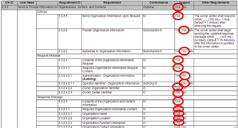
(Extended Text Description: A table showing a completed Needs to Requirements Matrix (NRTM). The table contents are shown below:
| UN ID | User Need | Requirement ID | Requirement | Conformance | Support | Other Requirements | |
|---|---|---|---|---|---|---|---|
| 2.3.2 | Need to Provide Information on Organizations, Centers, and Contacts | Optional | Yes/No | ||||
| Dialogs | |||||||
| 3.3.2.1 | Send Organization Information Upon Request | M | Yes | The owner center shall respond within ___ (100 ms - 1 hour; Default = 1 minute) after receiving the request. | |||
| 3.3.2.2 | Publish Organization Information | Subscription:O | Yes/No/NA | The owner center shall begin sending the updated response message within ___ (100 ms - 24 hours: Default = 15 minutes) after the information is updated in the owner center. | |||
| 3.3.2.3 | Subscribe to Organization Information | Subscription:O | Yes/No/NA | ||||
| Request Message | |||||||
| 3.3.2.4 | Contents of the Organization Information Request | M | Yes | ||||
| 3.3.2.4.1 | Required Organization Information Request Content | M | Yes | ||||
| 3.3.2.4.2.1 | Authentication - Organization Information (AuthOrg) | O | Yes/No | ||||
| 3.3.2.4.2.1.1 | Operator Identifier - Organization Information | AuthOrg:O | Yes/No/NA | ||||
| 3.3.2.4.2.2 | Owner Organization Identifier | O | Yes/No | ||||
| 3.3.2.4.2.3 | Owner Center Identifier | O | Yes/No | ||||
| Response Message | |||||||
| 3.3.2.5 | Contents of the Organization and Centers Information | M | Yes | ||||
| 3.3.2.5.1 | Required Organization Information Content | M | Yes | ||||
| 3.3.2.5.2.1 | Organization Name | O | Yes/No | ||||
| 3.3.2.5.2.2 | Organization Location | O | Yes/No | ||||
| 3.3.2.5.2.3 | Organization Function Description | O | Yes/No | ||||
| 3.3.2.5.2.4 | Organization Contact Information | O | Yes/No | ||||
Please note that in the graphical version of the table, the following items are circled in the "Support" column for this example, starting from top to bottom: Yes, Yes, No, No, Yes, Yes, No, No, Yes, Yes, Yes, Yes, Yes, Yes, Yes.)
Slide 48:
Learning Objective #3
Example Test Plan for a TMDD-based System
-
Approach:
- Organize tests by the selected features in the completed NRTM
- Modular Test Procedure Design (some data concepts fulfill multiple individual requirements, e.g., the data frame organizationInformation)
- Discuss how results are logged.
-
Items Pass/Fail:
- To pass the test, the item under test shall pass all test procedures associated with requirements for the test item identified in the NRTM.
Slide 49:
Learning Objective #3
Example Test Plan for a TMDD-based System
-
Suspension Criteria and Resumption Requirements:
- The test may be suspended between the performance of any two test procedures
- A test shall always resume at the start of a test procedure
- Any modifications to the test item(s) may require performing a regression test
Slide 50:
Learning Objective #3
Example Test Plan for a TMDD-based System
-
Test Deliverables:
- Test Plan: TP-TMDD-xxxx
- Test Design Specification: TD-TMDD-xxxx
- Test Case Specifications: TC-TMDD-xxxx
- Test Procedure Specifications: TPS-TMDD-xxxx
- Test Transmittal Reports
- Test Log Reports
- Test Incident Reports
- Test Summary Reports
Slide 51:
Learning Objective #3
Example Test Plan for a TMDD-based System
-
Testing Tasks:
- Develop Test Documentation (Test Plan, Test Design Specifications, Test Case Specifications, Test Procedure Specification)
- Training Workshop
- Prepare for Testing
- Conduct test and generate test logs
- Prepare Test Summary Report
- Transmit test documentation to project manager
Slide 52:
Learning Objective #3
Example Test Plan for a TMDD-based System
-
Environmental Needs:
- Test environment (facility, software programs); test items (ATMS software version); test hardware (laptops, servers, line analyzers, cabling, projectors, external drives for collecting test logs); test software (software programs, test database); documentation (TMDD v3.03 Standard in hardcopy, Test Plan in hardcopy)
-
Staffing and Training Needs
- Project Manager [Training - Yes], Test Analyst [Yes], Systems Integrator, QA/QC Manager [Yes]
Slide 53:
Learning Objective #3
Example Test Plan for a TMDD-based System
-
Responsibilities
- Project Manager - approve test plan; work with Team members to address concerns; witness the performance of the test; approve completion of tests
- Test Analyst - develop the test documentation; prepare the test environment; execute tests according to the test plan; verify test results against TMDD v3.03 standard
- Systems Integrator - witness the performance of the tests; resolve issues from the performance of the test; resolve areas of non-conformance
Slide 54:
Learning Objective #3
Example Test Plan for a TMDD-based System
-
Schedule
- Approval of Test Plan (TP-TMDD-xxxx): NTP
- Review and Documentation of Test Certificates and Test Setup: NTP + 9 days
- Perform TD-TMDD-xxxx, TC-TMDD-xxxx: NTP + 10 days ....
- Review Test Log Reports and Test Summary Reports: NTP + 20 to NTP + 25 days
- Recommendation (Approve, No Approval): NTP + 30 to NTP to 35 days
Slide 55:
Learning Objective #3
Example Test Plan for a TMDD-based System
-
Risk and Contingencies
- Unable to complete all Test Procedures on schedule. - Schedule remaining test procedures
- Agency X ATMS software and Agency Y ATMS software are unable to successfully exchange information - Conduct preliminary spot check if any major issues exist.
-
Approvals
- Names and titles of all persons to approve this plan.
Slide 56:

Slide 57:
Learning Objective #3
Which of the following is NOT in the TMDD Standard v3.03?
Answer Choices
- Needs to Requirements Traceability Matrix
- Requirements Traceability Matrix
- Requirements to Test Case Traceability Matrix
- A single design to fulfill each requirement
Slide 58:
Learning Objective #3
Review of Answers
 a) Needs to Requirements Traceability Matrix
Incorrect, a NRTM is included in the Standard.
 b) Requirements Traceability Matrix
Incorrect, an RTM is included in the Standard.
 c) Requirements to Test Case Traceability Matrix
Correct, this Matrix is not included in the Standard.
 d) A single design to fulfill each requirement
Incorrect, a single design is defined for each requirement in the Standard.
Slide 59:
Summary of Learning Objective #3
Describe the application of a good test plan to a TMDD-based system being procured using a sample TMDD test plan
- Described the structure of the TMDD v3.03 Standard
- Explained what is and is not to be tested when testing a TMDD-based system
- Reviewed a sample test plan for a TMDD-based system
Slide 60:
Learning Objective #4 - Identify the process to write a test plan in the context of the requirements of TMDD that have been selected by the user
- Use the NRTM to identify the features to be tested
- Use the RTM to determine the standard design to verify a requirement
-
Create a Requirements to Test Case Traceability Matrix
- Indicates the test case(s) that must be passed for the requirement to be fulfilled
- Verifies that the test cases capture testing of all requirements at least once
Slide 61:
Learning Objective #4
Process to Writing TMDD-based Test Plans
NRTM
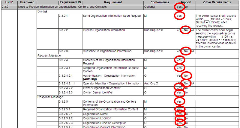
(Extended Text Description: This figure is the exact same figure in Slide 47, which is the table showing a completed Needs to Requirements Matrix (NRTM). Please see Slide 47 for detailed text description.)
Slide 62:
Learning Objective #4
Process to Writing TMDD-based Test Plans (cont.)
RTM
-
The Requirements Traceability Matrix (RTM) in the TMDD Standard defines a single (standard) design (in the form of dialogs, messages, data frames, data elements) that must be supported to fulfill a requirement.
- Dialogs are the sequence of data exchanges that are defined by the standard
Slide 63:
Learning Objective #4
Process to Writing TMDD-based Test Plans (cont.)
RTM
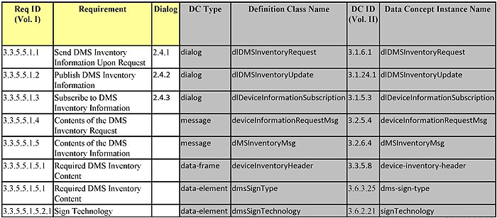
(Extended Text Description: This figure is a table showing a Requirements to Traceability Matrix. The table headings are Req. ID (Vol. I), Requirement, Dialog, DC Type, Definition Class Name, DC ID (Vol. II), and Data Concept Instance Name. The focus of this slide is only on the first 3 columns, so the remaining columns are shaded. The complete table is shown below:
| Req ID (Vol. I) | Requirement | Dialog | DC Type | Definition Class Name | DC ID (Vol. II) | Data Concept Instance Name |
|---|---|---|---|---|---|---|
| 3.3.5.5.1.1 | Send DMS Inventory Information Upon Request | 2.4.1 | dialog | dlDMSInventoryRequest | 3.1.6.1 | dlDMSInventoryRequest |
| 3.3.5.5.1.2 | Publish DMS Inventory Information | 2.4.2 | dialog | dlDMSInventoryUpdate | 3.1.24.1 | dlDMSInventoryUpdate |
| 3.3.5.5.1.3 | Subscribe to DMS Inventory Information | 2.4.3 | dialog | dlDeviceInformationSubscription | 3.1.5.3 | dlDeviceInformationSubscription |
| 3.3.5.5.1.4 | Contents of the DMS Inventory Request | message | deviceInformationRequestMsg | 3.2.5.4 | deviceInformationRequestMsg | |
| 3.3.5.5.1.5 | Contents of the DMS Inventory Information | message | dMSInventoryMsg | 3.2.6.4 | dMSInventoryMsg | |
| 3.3.5.5.1.5.1 | Required DMS Inventory Content | data-frame | deviceInventoryHeader | 3.3.5.8 | device-inventory-header | |
| 3.3.5.5.1.5.1 | Required DMS Inventory Content | data-element | dmsSignType | 3.6.3.25 | dms-sign-type | |
| 3.3.5.5.1.5.2.1 | Sign Technology | data-element | dmsSignTechnology | 3.6.2.21 | signTechnology |
)
Slide 64:
Learning Objective #4
Process to Writing TMDD-based Test Plans (cont.)
RTM

(Extended Text Description: This figure is a table showing the same Requirements to Traceability Matrix in Slide 63. The table headings are Req. ID (Vol. I), Requirement, Dialog, DC Type, Definition Class Name, DC ID (Vol. II), and Data Concept Instance Name. The focus of this slide is only on the last 4 columns, so the first 3 columns are shaded. Please see Slide 63 for the complete table data.)
Slide 65:
Learning Objective #4
Process to Writing TMDD-based Test Plans (cont.)
RTM
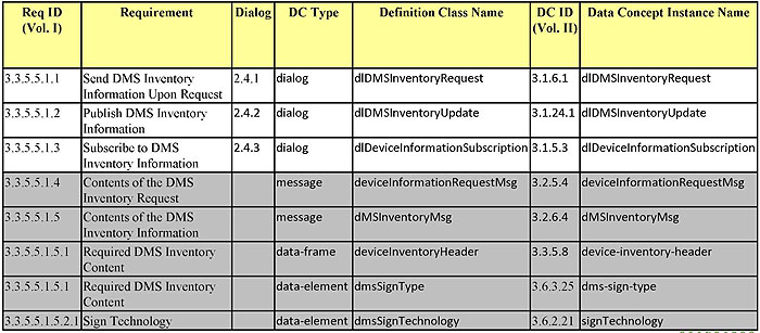
(Extended Text Description: This figure is a table showing the same Requirements to Traceability Matrix in Slide 63. The table headings are Req. ID (Vol. I), Requirement, Dialog, DC Type, Definition Class Name, DC ID (Vol. II), and Data Concept Instance Name. The focus of this slide is only on the first 3 rows, so the last 5 rows are shaded. Please see Slide 63 for the complete table data.)
Slide 66:
Learning Objective #4
Process to Writing TMDD-based Test Plans (cont.)
RTM
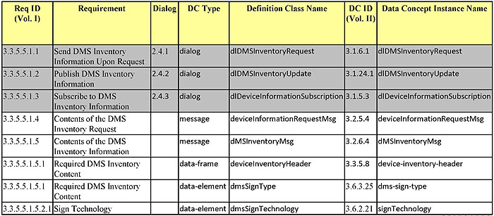
(Extended Text Description: This figure is a table showing the same Requirements to Traceability Matrix in Slide 63. The table headings are Req. ID (Vol. I), Requirement, Dialog, DC Type, Definition Class Name, DC ID (Vol. II), and Data Concept Instance Name. The focus of this slide is only on the last 5 rows, so the first 3 rows are shaded. Please see Slide 63 for the complete table data.)
Slide 67:
Learning Objective #4
Process to Writing TMDD-based Test Plans (cont.)
Design
- Below is the dialog that fulfills this requirement.
3.1.6.1.2 ASN.1 REPRESENTATION
dlDMSInventoryRequest ITS-INTERFACE-DIALOGUE ::= {
DESCRIPTIVE-NAME "ExternalCenter<-DlDMSInventoryRequest->OwnerCenter"
ASN-NAME "DlDMSInventoryRequest"
ASN-OBJECT-IDENTIFIER { tmddDialogs 16 }
URL "R-R.gif"
DEFINITION "A request-response dialog that allows an external center to request an owner center to provide an inventory of the owner center's dynamic message signs."
DESCRIPTIVE-NAME-CONTEXT {"Manage Traffic"}
ARCHITECTURE-REFERENCE {"device data"}
ARCHITECTURE-NAME {"U.S. National ITS Architecture"}
ARCHITECTURE-VERSION {"7.0"}
DATA-CONCEPT-TYPE interface-dialogue
STANDARD "TMDD" REFERENCED-MESSAGES {
{ tmddMessages 20 }, -- deviceInformationRequestMsg (Input Message)
{ tmddMessages 25 }, -- dMSInventoryMsg (Output Message)
{ tmddMessages 10 } --errorReportMsg (Fault Message) }
Slide 68:
Learning Objective #4
Process to Writing TMDD-based Test Plans (cont.)
Design
-
The test should confirm that the interface:
- performs the same sequence of data exchanges (and events) as defined in the standard
- uses the data concepts (messages, data frames or data elements) indicated in the RTM
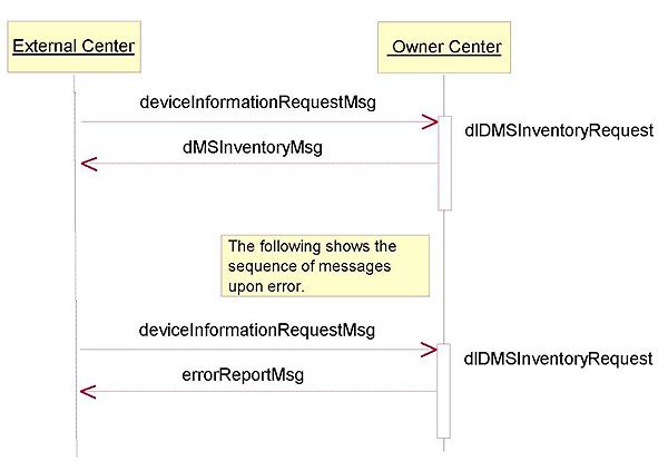
(Extended Text Description: The figure is a Unified Modeling Language (UML) sequence diagram representing the dlDMSInventoryRequest dialog. A box in the upper left hand corner labeled External Center indicates that the left side is the External Center and a box in the upper right hand corner labeled Owner Center indicates that the right side is the Owner Center. Time is represented by moving down the diagram. Under the boxes, is a line is from the left side pointing to the right side, labeled deviceInformationRequestMsg, indicating a deviceInformationRequestMsg is being transmitted from the External Center to the Owner Center. Below that first line is another line from the right side pointing to the left side labeled dMSInventoryMsg, indicating that at a later time, the dMSInventoryMsg is transmitted back from the Owner Center to the External Center in response to the deviceInformationRequestMsg. A second set of lines shows the sequence of messages upon error. This second set of lines begin with a line from the left side pointing to the right side, labeled deviceInformationRequestMsg, indicating a deviceInformationRequestMsg is being transmitted from the External Center to the Owner Center. Below that first line is another line from the right side pointing to the left side labeled errorReportMsg, indicating that at a later time, the errorReportMsg is transmitted back from the Owner Center to the External Center in response to the deviceInformationRequestMsg.)
Slide 69:
Learning Objective #4
Process to Writing TMDD-based Test Plans (cont.)
Requirements to Test Case Traceability Matrix
-
Create a Requirements to Test Case Traceability Matrix (RTCTM)
- Traces each requirement selected to the test case(s) that verifies that the implementation fulfills the requirement
- Used to verify that the test cases capture testing of all requirements at least once.
-
One or more test cases may be needed to completely test a requirement
- Each test case may test a different set of values
- Each test case may test different conditions
Slide 70:
Learning Objective #4
Process to Writing TMDD-based Test Plans (cont.)
Requirements to Test Case Traceability Matrix
| Requirement | Test Case | ||
|---|---|---|---|
| ID | Title | ID | Title |
| 3.3.2.1 | Send Organization Information Upon Request | ||
| TCS-1.2.1 | Verify Organization Information with No Errors | ||
| TCS-1.2.2 | Verify Organization Information with Errors | ||
| 3.3.2.4 | Contents of the Organization Information | ||
| TCS-1.2.1 | Verify Organization Information with No Errors | ||
| TCS-1.2.2 | Verify Organization Information with Errors | ||
Slide 71:

Slide 72:
Learning Objective #4
Which of the following is part of the Requirements to Test Case Traceability Matrix?
Answer Choices
- User Needs
- Requirements
- Design
- Test Plans
Slide 73:
Learning Objective #4
Review of Answers
 a) User Needs
Incorrect, user needs only appear in a NRTM.
 b) Requirements
Correct, requirements are part of the matrix.
 c) Design
Incorrect, design only appears in an RTM.
 d) Test Plans
Incorrect, Test Cases are part of the RTCTM.
Slide 74:
Summary of Learning Objective #4
Identify the process to write a test plan in the context of the requirements of TMDD that have been selected by the user
- Use the NRTM to identify the features to be tested
- Use the RTM to determine the standard design to verify a requirement
-
Create a Requirements to Test Case Traceability Matrix
- Indicates the test case(s) that must be passed for the requirement to be fulfilled
- Verifies that the test cases capture testing of all requirements at least once
Slide 75:
Learning Objective #5 - Analyze how to ensure conformance with the TMDD v3.03 Standard
- Review the Key Elements of the Conformance Statement
- Discuss extensions to the TMDD Standard
Slide 76:
Learning Objective #5
Conformance for a TMDD-based System
-
Interoperability is the ability of different components, or for the purpose of this module, different TMDD-based implementations from different vendors, to exchange information and to use the information that has been exchanged.
- Interoperability is a key objective for using the standards
- Interoperability reduces risks and, by extension, costs.
Slide 77:
Learning Objective #5
Conformance for a TMDD-based System
-
TMDD supports interoperability by defining a single (standard) design (in the form of dialogs, messages, data frames, data elements) to fulfill each requirement supported by the standard.
- It defines the sequence of events (actions) and the data that must be exchanged.
- All systems shall fulfill a requirement the same way.
- By conforming to a standard - achieve interoperability.
Slide 78:
Learning Objective #5
Conformance for a TMDD-based System
-
To claim conformance to the TMDD Standard:
- An implementation shall satisfy all user needs identified as Mandatory in the NRTM; and all user needs identified as Optional in the NRTM, but was selected (to be supported) for the implementation
-
To claim conformance to a user need in the TMDD Standard:
- An implementation shall fulfill all requirements that trace to the user need identified as Mandatory in the NRTM; and all requirements that trace to the user need identified as Optional in the NRTM, but was selected (to be supported) for the implementation
Slide 79:
Learning Objective #5
Conformance for a TMDD-based System
-
To claim conformance to a requirement in the Standard
- An implementation fulfill a requirement by using all of the data concepts (dialogs, messages, data frames, and data elements) traced to the requirement in the RTM in the manner specified by this Standard or the referenced Standard
Slide 80:
Learning Objective #5
Conformance for a TMDD-based System
-
TMDD Standard allows for extensions to support operational or user needs not supported by the Standard
- Benefits include it allows an implementation to add functions not supported by the standard
- By definition, implementations that add extensions are no longer conformant to the standard
-
With extensions, interoperability may be compromised
- Other centers must support extensions in a consistent manner to support interoperability
- Test documentation needs to be expanded to support extensions
Slide 81:
Learning Objective #5
Conformance for a TMDD-based System
-
To be consistent with the TMDD Standard, the following rules shall apply:
- All functional requirements already supported by the Standard must be implemented as defined by the Standard
- Different interpretations of the meaning of a data concept or how it is to be used requires a new data concept
- A conformant center receiving a message must ignore any attributes or elements in a message that it does not recognize but shall process what it understands
Slide 82:
Learning Objective #5
Conformance for a TMDD-based System
-
To be consistent with the TMDD Standard, the following rules shall apply:
- New data elements may be added but cannot reuse an existing data element name
- New enumerations may be added in a newly created data element, but cannot reuse an existing data element name
- Extending the range of an existing data element requires that the data element be renamed
- New messages may be added beyond those messages defined by the standard, but cannot reuse an existing message name
Slide 83:
Learning Objective #5
Conformance for a TMDD-based System
-
To be consistent with the TMDD Standard, the following rules shall apply:
- Dialogs contained in the Standard may not be modified. However, new dialogs may be added to support extensions.
- All design extensions (e.g., dialogs, messages data frames, and data elements) shall be documented in a separate XML schema (or ASN.1 module).
- All extensions shall be documented in a manner consistent with the presentation in the standard, and shall include the user needs being addressed, the requirements being fulfilled, and the traceability tables.
Slide 84:
Learning Objective #5
Conformance for a TMDD-based System
When adding extensions:
- NRTM should be updated to include any new user needs and any new requirements
- RTM should be updated to include the new data concepts (dialogs, messages, data frames and data elements) to fulfill each new requirement
- The Requirements to Test Case Traceability Matrix should be updated to reflect the Test Case Specifications and Test Procedure Specifications to be performed to test each new requirement
Slide 85:

Slide 86:
Learning Objective #5
Which of the following is permitted by the TMDD Standard?
Answer Choices
- Create a new message to fulfill a new requirement
- Change the meaning of an existing data element
- Create a new data element using an existing data element name
- Modify an existing dialog
Slide 87:
Learning Objective #5
Review of Answers
 a) Create a new message to fulfill a new requirement
Correct, creating a new message to fulfill a new requirement is allowed.
 b) Change the meaning of an existing data element
Incorrect, changing the meaning of an existing data element is not permitted.
 c) Create a new data element using an existing data element name
Incorrect, reusing the name of an existing data concept for a new data concept is not permitted.
 d) Modify an existing dialog
Incorrect, modifying an existing dialog is not permitted.
Slide 88:
Summary of Learning Objective #5
Analyze how to ensure conformance with the TMDD v3.03 Standard
- Review the Key Elements of the Conformance Statement
- Discuss extensions to the TMDD Standard
Slide 89:
Learning Objective #6 - Describe test documentation for TMDD: Test Plan, Test Design Specification, Test Case Specifications, and Test Reports
- Review the elements that comprise each type of test documentation that is part of a test plan
- Introduce the Reference Implementation
Slide 90:
Learning Objective #6
Test Documentation for a TMDD-based System
- Test Documentation, such as the Test Plan, can begin to be written after the user needs and requirements are finalized, e.g., after the NRTM has been completed and is finalized.
Slide 91:
Learning Objective #6
Test Documentation for a TMDD-based System (cont.)
| "V" Element | TMDD Document | TMDD-based Test Document |
|---|---|---|
| Concept of Operations | Needs To Requirements Matrix | Basis for Test Plan |
| System Requirements | Requirements Traceability Matrix | Basis for Test Design Specifications |
| High-Level & Detailed Design | Dialogs, messages, data frames, and data elements | Basis for Test Case Specifications and Test Procedure Specifications |
| Implementation | Not Applicable | Basis for Test Execution and Resulting Test Reports |
Slide 92:
Learning Objective #6
Test Documentation for a TMDD-based Syst em
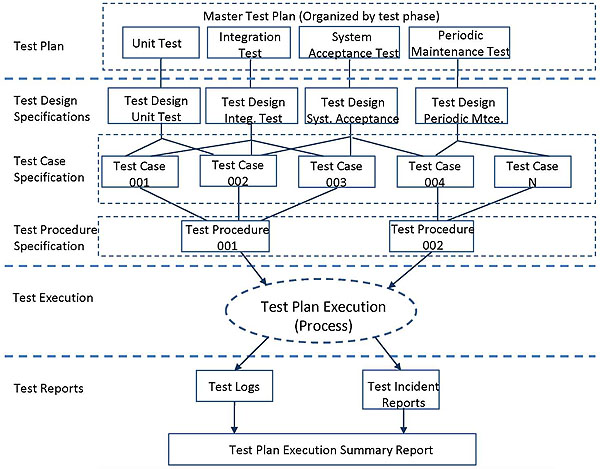
(Extended Text Description: This figure is a diagram showing the relationship between the different test documents. The first row of boxes represents a Test Plan, with a large box labeled Master Test Plan (organized by test phase), and within that box are 4 smaller boxes, labeled Unit Test, Integration Test, System Acceptance Test, and Periodic Maintenance Test. The next row represents Test Design Specifications and contains four boxes. There is a line leading from the first box in the first row to the first box in the second row, a line from the second box in the first row to the second box in the second row, etc... The first box is the second row is labeled Test Design Unit Test, the second box is Test Design Integration Test, the third box is Test Design System Acceptance, and the fourth box is labeled Test Design Periodic Maintenance. The third row of boxes represents Test Case Specifications and consists of a large box, with five smaller boxes within it. The smaller boxes are labeled Test Case 001, Test Case 002, Test Case 003, Test Case 004, and Test Case N. There are random lines from the four smaller boxes in the second row to the different smaller boxes in the third row. The fourth row represents Test Procedure Specifications and contains of a large box, with two smaller boxes within it. The first small box is labeled Test Procedure 001, and the second small box is labeled Test Procedure 002. There are lines from Test Case 001, Test Case 002, and Test Case 003 to Test Procedure 001, and lines from Test Case 004 and Test Case N to Test Procedure 002. The next row represents Test Execution and is an oval labeled Test Plan Execution (Process). The last two rows represent Test Reports. The first row of the Test Reports has two boxes, one labeled Test Logs and the other labeled Test Incident Reports. There is a line from Test Plan Execution (Process) to Test Logs and Test Incident Reports. The last row is a box labeled Test Plan Execution Summary Report, and there is a line from Test Logs and Test Incident Reports to this box.)
Slide 93:
Learning Objective #6
Test Documentation for a TMDD-based System (cont.)
- Test documentation development in the initial phase is an iterative process (with the exception of the test reports).
- Test documentation developers may need to work on several documents concurrently to maintain consistency (i.e., consistent referencing - e.g., Test Design to Test Cases)
Slide 94:
Learning Objective #6
Test Design Specifications
- Identifies the features to be covered by the design and its associated tests.
- Identifies the test cases and test procedures required to accomplish the testing and specifies the pass/fail criteria.
-
May have separate Test Design Specifications
- By System Life Cycle Phase
- By Functional Area
- E.g., there may be one test design specification for CCTV cameras, and a second test design specifications for dynamic message signs)
Slide 95:
Learning Objective #6
Example Test Design Specification for a TMDD-based System
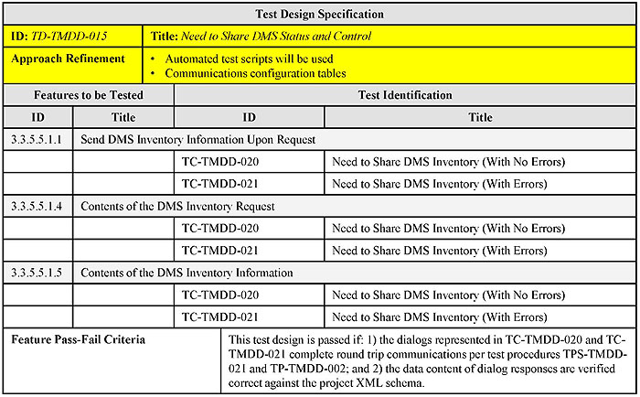
(Extended Text Description: This table shows an Example Test Design Specification for a TMDD-based System. For the purposes of this slide, the following two rows are highlighted: ID/Title and Approach Refinement. The complete table data is shown below:
| Test Design Specification | |||||
|---|---|---|---|---|---|
| ID: TD-TMDD-015 | Title: Need to Share DMS Status and Control | ||||
| Approach Refinement |
|
||||
| Features to be Tested | Test Identification | ||||
| ID | Title | ID | Title | ||
| 3.3.5.5.1.1 | Send DMS Inventory Information Upon Request | ||||
| TC-TMDD-020 | Need to Share DMS Inventory (With No Errors) | ||||
| TC-TMDD-021 | Need to Share DMS Inventory (With Errors) | ||||
| 3.3.5.5.1.4 | Contents of the DMS Inventory Request | ||||
| TC-TMDD-020 | Need to Share DMS Inventory (With No Errors) | ||||
| TC-TMDD-021 | Need to Share DMS Inventory (With Errors) | ||||
| 3.3.5.5.1.5 | Contents of the DMS Inventory Information | ||||
| TC-TMDD-020 | Need to Share DMS Inventory (With No Errors) | ||||
| TC-TMDD-021 | Need to Share DMS Inventory (With Errors) | ||||
| Feature Pass-Fail Criteria | This test design is passed if: 1) the dialogs represented in TC-TMDD-020 and TC-TMDD-021 complete round trip communications per test procedures TPS-TMDD-021 and TP-TMDD-002; and 2) the data content of dialog responses are verified correct against the project XML schema. | ||||
)
Slide 96:
Learning Objective #6
Example Test Design Specification for a TMDD-based System

(Extended Text Description: This slide contains the same table shown in Slide 95, only different rows and cells are highlighted. In this slide, the three rows related to ID 3.3.5.5.1.1 and the cell to the right of Feature Pass-Fail Criteria are highlighted. Please see Slide 95 for the complete table contents.)
Slide 97:
Learning Objective #6
Test Case Specification
- Specifies the inputs, predicted results, and a set of execution conditions for a test item.
- Recall: The RTM defines the dialogs and data concepts that must be supported to fulfill a requirement. How is the requirement fulfilled?
-
Recall: The RTCTM defines the test case(s) that must be passed to verify a requirement is fulfilled.
- The test case(s) should confirm that the system performs the same sequence of data exchanges (and events) or use the data concepts to fulfill the requirement being verified.
Slide 98:
Learning Objective #6
Test Case Specification

(Extended Text Description: This table is entitled Test Case Specification. For the purposes of this slide, the following two rows are highlighted: ID/Title and Test Case Objectives. The complete table data is shown below:
| Test Case Specification | |
|---|---|
| ID: TC-TMDD-020 | Title: Need to Share DMS Inventory |
| Test Case Objectives | To verify the ability for an owner center and an external center to exchange the inventory and configuration of the dynamic message signs operated by the owner center. |
| Test Items |
|
| Input Specifications | TCI-TMDD-020-1 - Need to Share DMS Inventory Inputs |
| Output Specifications | TCO-TMDD-020-1 - Need to Share DMS Inventory Outputs |
| Environmental Needs | No additional needs outside of those specified in the test plan |
| Special Procedure Requirements | None |
| Intercase Dependencies | Perform test case TC-TMDD-019, Need to Share Updated DMS Inventory to set up a subscription. |
)
Slide 99:
Learning Objective #6
Test Case Specification

(Extended Text Description: This slide contains the same table shown in Slide 98, only different rows are highlighted. In this slide, the three rows related to Test Items, Input Specifications, and Output Specifications are highlighted. Please see Slide 98 for the complete table contents.)
Slide 100:
Learning Objective #6
Test Case Specification
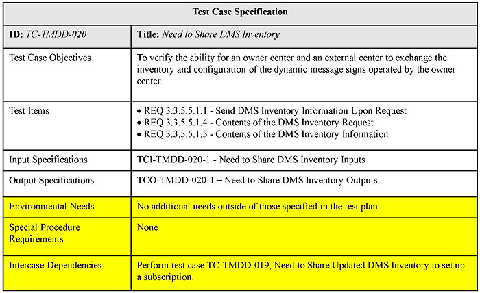
(Extended Text Description: This slide contains the same table shown in Slide 98, only different rows are highlighted. In this slide, the three rows related to Environmental Needs, Special Procedure Requirements, and Intercase Dependencies are highlighted. Please see Slide 98 for the complete table contents.)
Slide 101:
Learning Objective #6
Example Test Case Input Specification for a TMDD-based System

(Extended Text Description: This table shows an Example Test Case Input Specification for a TMDD-based System. For the purposes of this slide, the following two column data are highlighted: FR ID and DC Type. The complete table data is shown below:
| Test Case Input Specification | ||||
|---|---|---|---|---|
| ID: TCI-TMDD-020-1 | Title: Need to Share DMS Inventory Inputs | |||
| FR ID | DC Type | DC Instance Name | DC ID | Value |
| Dialog (For Reference Only) | ||||
| 3.3.5.5.1.1 | dialog | dlDMSInventoryRequest | 3.1.6.1 | - |
| Request Message | ||||
| 3.3.5.1.1.1 | message | deviceInformationRequestMsg | 3.2.5.4 | - |
| 3.3.5.1.1.1.1 | data-frame | organization-information | 3.3.16.3 | - |
| data-element | organization-id | 3.4.16.8 | Center5 | |
| 3.3.5.1.1.1.1 | data-element | device-type | 3.4.5.15 | Enumerated. dynamic-message-sign (3) |
| 3.3.5.1.1.1.1 | data-element | device-information-type | 3.4.5.7 | Enumerated. device-inventory (1) |
| 3.3.5.5.1.4 | message | deviceInformationRequestMsg | 3.2.5.4 | |
)
Slide 102:
Learning Objective #6
Example Test Case Input Specification for a TMDD-based System
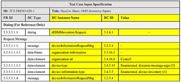
(Extended Text Description: This slide contains the same table shown in Slide 101, only different columns are highlighted. In this slide, the three columns related to DC Instance Name, DC ID, and Value are highlighted. Please see Slide 101 for the complete table contents.)
Slide 103:
Learning Objective #6
Example Test Case Specification for a TMDD-based System
| Test Case Output Specification | ||||
|---|---|---|---|---|
| ID: TCO-TMDD-020-1 | Title: Need to Share DMS Inventory Inputs | |||
| FR ID | DC Type | DC Instance Name | DC ID | Value Domain |
| Dialog (For Reference Only) | ||||
| 3.3.5.5.1.1 | dialog | dlDMSInventoryRequest | 3.1.6.1 | - |
| Response Message | ||||
| 3.3.5.1.2.1 | data-frame | deviceInventoryHeader | 3.3.5.8 | - |
| 3.3.5.1.2.1.1 | data-frame | organization-information | 3.3.16.3 | - |
| 3.3.5.1.2.1.1 | data-element | device-id | 3.4.16.8 | AgencyA-DMS-006 |
| 3.3.5.1.2.1.1 | data-frame | device-location | 3.6.9.4 | - |
| 3.3.5.1.2.1.1 | data-element | device-name | 3.4.16.9 | DMSI-495NB-MM128.3 |
| 3.3.5.5.1.5 | message | dMSInventoryMsg | 3.2.6.4 | - |
| 3.3.5.5.1.5.1 | data-frame | device-inventory-header | 3.3.5.8 | - |
| 3.3.5.5.1.5.1 | data-frame | dms-sign-type | 3.6.3.35 | Enumerated. Should be: vmsLine (5) |
Slide 104:
Learning Objective #6
Test Procedure Specification
-
Specifies the sequence of actions for the execution of a test.
- It is important not to skip any steps in the test procedures to ensure proper conformance testing.
-
Set up test procedures so that they may be reused.
- For example, the Authentication data frame appears in every request message in TMDD v3.03.
- Create a test procedure specification to verify the Authentication requirement.
- For each test procedure to verify a request message, call the Authentication test procedure specification if applicable.
Slide 105:
Learning Objective #6
Example Test Procedure Specification for a TMDD-based System

(Extended Text Description: This table shows an Example Test Procedure Specification for a TMDD-based System. For the purposes of this slide, the following four rows are highlighted: ID/Title, Scope, Special Requirements and the row below Preconditions. The complete table data is shown below:
| Test Procedure | ||||
|---|---|---|---|---|
| ID: TPS-TMDD-021 | Title: Need to Share DMS Inventory Procedures | |||
| Scope | This test procedure verifies that the dlDMSInventoryRequest dialog of an Owner Center system interface is implemented properly. It tests when a deviceInformationRequestMsg is sent to an owner center, that the owner center responds with an dMSInventoryMsg response message. | |||
| Special Requirements | None | |||
| Preconditions | ||||
|
1. Verify that the XML Request Message is valid against Project XML Schema 2. Verify that the WSDL for the Dialog to be tested is correct |
||||
| Step | Test Procedure | Results | References | |
| 1 | CONFIGURE: Determine the identifier, location, name, and type of the dynamic message sign (per the Owner Center's database) being requested from the Owner Center. RECORD that information as, respectively: dms_id, dms_location, dms_name, dms_type | |||
| 2 |
SETUP: Check the deviceInformationRequestMsg inputs so: >organization-id = "Center5" >device-type = "dynamic-message-sign (3)" >device-information-type = "device-inventory (1)" |
TCI-TMDD-020-1 | ||
| 3 | SETUP: Start HTTP Client | |||
| 4 | Load XML deviceInformationRequestMsg | |||
| 5 | Send XML deviceInformationRequestMsg to Owner Center | Pass / Fail | TMDD Vol. II (3.1.6.1) | |
| 6 | Receive XML dMSInventoryMsg from Owner Center | Pass / Fail | TMDD Vol. II (3.1.6.1) | |
| 7 | Log XML dMSInventoryMsg from Owner Center to a log file. | |||
)
Slide 106:
Learning Objective #6
Example Test Procedure Specification for a TMDD-based System

(Extended Text Description: This slide contains the same table shown in Slide 105, only different rows are highlighted. In this slide, the seven rows under Step are highlighted. Please see Slide 105 for the complete table contents.)
Slide 107:

Slide 108:
Learning Objective #6
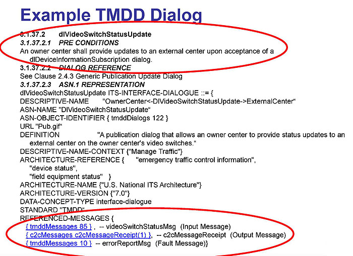
(Extended Text Description: This slide contains an Example TMDD Dialog with the following text:
Example TMDD Dialog
3.1.37.2 dlVideoSwitchStatusUpdate
3.1.37.2.1 PRE CONDITIONS
An owner center shall provide updates to an external center upon acceptance of a dlDevicelnformationSubscription dialog.
3.1.37.2.2 DIALOG REFERENCE
See Clause 2.4.3 Generic Publication Update Dialog
3.1.37.2.3 ASN.1 REPRESENTATION
dlVideoSwitchStatusUpdate ITS-INTERFACE-DIALOGUE {
DESCRIPTIVE-NAME "OwnerCenter<-DlVideoSwitchStatusUpdate->ExternalCenter"
ASN-NAME "DlVideoSwitchStatusUpdate"
ASN-OBJECT-IDENTIFIER { tmddDialogs 122 }
URL "Pub.gif"
DEFINITION "A publication dialog that allows an owner center to provide status updates to an external center on the owner center's video switches."
DESCRIPTIVE-NAME-CONTEXT {"Manage Traffic"}
ARCHITECTURE-REFERENCE { "emergency traffic control information",
"device status",
"field equipment status" }ARCHITECTURE-NAME {"U.S. National ITS Architecture"}
ARCHITECTURE-VERSION {"7.0"} DATA-CONCEPT-TYPE interface-dialogue
STANDARD "TMDD"
REFERENCED-MESSAGES {
{ tmddMessages 85 }, -- videoSwitchStatusMsg (Input Message)
{ c2cMessages c2cMessageReceipt(1) }, --c2cMessageReceipt (Output Message)
{ tmddMessages 10 } -- errorReportMsg (Fault Message)}
Additional descriptive notes: Please note that on the example graphical slide, there are two red ovals encircling the first five lines of text starting with 3.1.37.2 and the bottom four lines of text starting with REFERENCED-MESSAGES.)
Slide 109:
Learning Objective #6
Which of the following is not an appropriate test step for the previous dialog?
Answer Choices
- The Owner Center sends the videoSwitchStatusMsg to the External Center
- Pre-condition to execute the dlDevicelnformationSubscription dialog
- The External Center sends a c2cMessageReceipt message to the Owner Center
- The External Center sends a devicelnformationRequestMsg to the Owner Center
Slide 110:
Learning Objective #6
Review of answers
 a) The Owner Center sends the videoSwitchStatusMsg to the External Center
Incorrect, videoSwitchStatusMsg is the input message for the dialog
 b) Precondition to execute the dlDeviceInformationSubscription dialog
Incorrect, dlDeviceInformationSubscription is a pre-condition for the dialog
 c) The External Center sends a c2cMessageReceipt message to the Owner Center
Incorrect, c2cMessageReceipt is the output message for this dialog
 d) The External Center sends a devicelnformationRequestMsg to the Owner Center
Correct, the External Center sends a c2cMessageReceipt to the Owner Center
Slide 111:
Learning Objective #6
Test Log
- Provides a chronological record of relevant details about the execution of the tests
- Identifies the tester(s)
- Identifies the items being tested (including version levels) and the test environment
-
Includes the identifier of the test procedure being executed, records the results, and indicates if the test has been successfully executed or not.
- May include a completed copy of the test procedure specifications with approval signatures
- May include printer outputs, screen snapshots, etc... to verify a test result
Slide 112:
Learning Objective #6
Test Incident Report
- Documents any event that occurs during testing that requires additional investigation
- Includes a summary of the incident
- Identifies the inputs, the expected results, the actual results, any anomalies observed, the date and time of the event, the test procedure (and step) being executed, and the observers
- Indicate the impacts that the incident will have on the test plan, test design specifications, test case specifications, and test procedure specifications
Slide 113:
Learning Objective #6
Test Summary Report
- Summarizes of the results from the testing activities and provides an evaluation based of the test items based on these results.
- Notes any variances, and the reasons, of the test items from the design specifications (or standard), test plan, test designs, or test procedures.
- Specifies the names of all persons who must approve this report.
Slide 114:
Learning Objective #6
Reference Implementation
- Motivation: TMDD v3.03 consists of 122 user needs and 1,160 requirements. Developing test plans, test cases, and test procedures is an enormous effort.
-
USDOT developed a Reference Implementation (RI) tool to aid in performing testing of center-to-center interfaces. The RI:
- Allows the user to create a test configuration based on its selected user needs and requirements
- Executes the test
- Creates test reports
Slide 115:
Learning Objective #6
Reference Implementation (cont.)
-
Follows a systems engineering process and the IEEE 829 standard
- Includes the key elements of the TMDD standard relevant to testing: NRTM, requirements, and a Requirements to Test Case Traceability Matrix
- Includes or uses test documentation such as test design specifications, test case specifications, and test procedure specifications
- Outputs test reports and test logs
- Supports XML implementations only, not designed for ASN.1 implementations
Slide 116:
Learning Objective #6
Reference Implementation (cont.)
-
Allows custom test configurations to define the requirements for the C2C interface
- Allows the user to select the Information Layer Standard, Application Layer Standard, and indicate if the RI acts as the owner center or the external center
- Allows the user to identify the System Under Test (IP address, location of web services, username/password)
Slide 117:
Learning Objective #6
Reference Implementation (cont.)
-
Configure Information Layer Parameters
- Select the Information Layer user needs to be tested
- Based on the user need highlighted, select the requirements to be tested
- The NRTM is shown, indicating any predicates, and if the requirement is mandatory or optional
- All mandatory user needs and requirements are preselected
- Any additional specifications in the NRTM can be filled in
Slide 118:
Learning Objective #6
Reference Implementation (cont.)
-
The RI provides a list of test case(s) that are applicable based on the user needs / requirements selected in the test configuration file
- Allows for the selection of test cases to be executed, including the selection of user-defined test cases
-
The RI executes the tests
- Provides the results of each test case and each test procedure step on the screen
-
Provides Test Reports
- Includes Conformance / Compliance reports for each user need and requirement selected
- Highlights any errors that were encountered
Slide 119:
Learning Objective #6
Reference Implementation (cont.)
-
An official test suite is provided. Includes:
- A TMDD Standard WSDL and Schema definition
- The NRTM as defined in TMDD 3.03
- A Requirements to Test Case Traceability Matrix
- Test Case Definition files - identifies data parameters and expected results of each test case
- Test Procedures Scripts
-
User-defined test suites can be created
- Support user-defined user needs and requirements
- Support additional test cases and test procedure scripts
Slide 120:
Learning Objective #6
Reference Implementation (cont.)
-
Verifies:
- Compliance with a specification
- Conformance with the standards (TMDD v3.03 and NTCIP 2306 v1.69)
-
Does NOT verify
- How the data is used in the implementation's environment
- The operation(s) the implementation is attempting to support via the interface
-
Cannot validate the system:
- Can the agency use the system as expected?
- Does it address the problem (satisfy the user need)?
Slide 121:
Learning Objective #6
Other Test Tools
XML Schema Validator
-
Validate an XML document (i.e., TMDD message) against the TMDD Schema
- Verify the XML structure is well-formed
- Verify Structure of Data is Correct
- Verify Data Content is Correct
Slide 122:
Learning Objective #6
Summary of Learning Objective #6
Describe test documentation for TMDD: Test Plan, Test Design Specification, Test Case Specifications, and Test Reports
- Review the elements that comprise each type of test documentation that is part of a test plan
- Introduce the Reference Implementation
Slide 123:
What We Have Learned
- We test a TMDD-based system interface to verify it fulfills the system requirements and to validate it satisfies the user needs.
- The test plan for a TMDD-based system interface defines what portion of the system interface is to be tested.
- A completed NRTM and RTM are key elements of the TMDD standard that should be used to develop the test plan.
- A Requirementsto Test CaseTraceability Matrix should be created to ensure all requirements are tested at least once.
Slide 124:
What We Have Learned
- The TMDD Standard supports interoperability by defining a single design to fulfill each requirement.
- Extensions are allowed by the TMDD Standard but are discouraged.
- The Reference lmplementation is a tool to aid in performing testing of center-to-center interfaces.
Slide 125:
Resources
- T321 Student Supplement
- TMDD v3.03 Standard for Traffic Management Center-to-Center Communications Volumes I and II - www.ite.org/standards/tmdd
- TMDD Guide - http://www.ite.org/standards/TMDDstandardv03Guide.pdf
- NTCIP 9001 v04 -The NTCIP Guide - www.ntcip.org
- NTCIP 8007, Testing and Conformity Assessment Documentation within NTCIP Standards - www.ntcip.org
Slide 126:
