Module 36 - T317
T317: Applying Your Test Plan to NTCIP 1205 Standard
HTML of the PowerPoint Presentation
(Note: This document has been converted from a PowerPoint presentation to 508-compliant HTML. The formatting has been adjusted for 508 compliance, but all the original text content is included, plus additional text descriptions for the images, photos and/or diagrams have been provided below.)
Slide 1:
(Extended Text Description: Slide 1: Welcome - Graphic image of introductory slide. A large dark blue rectangle with a wide, light grid pattern at the top half and bands of dark and lighter blue bands below. There is a white square ITS logo box with words "Standards ITS Training" in green and blue on the middle left side. The word "Welcome" in white is to the right of the logo. Under the logo box are the words "RITA Intelligent Transportation Systems Joint Program Office.")
Slide 2:
Welcome

Ken Leonard, Director
ITS Joint Program Office

(Extended Text Description: Intro Slide: Screen capture snapshot of RITA website - for illustration only. Below this image is a link to the current website: https://www.its.dot.gov/pcb - this screen capture snapshot shows an example from the RITA website from April 2013. At the top of the page it shows the RITA logo with the text U.S. Department of Transportation Research and Innovative Technology Administration - Intelligent Transportation Systems Joint Program Office - ITS Professional Capacity Building Program/Advanced ITS Education. Below the main site banner, it shows the main navigation menu with the following items: About, ITS Training, Knowledge Exchange, Technology Transfer, ITS in Academics, and Media Library. Below the main navigation menu, the page shows various content of the website, including a graphic image of professionals seated in a room during a training program. A text overlay has the text Welcome to ITS Professional Capacity Building. Additional content on the page includes a box entitled What's New and sections entitled Available E-Training (free), Free ITS Training and T3 Webinars. Again, this image serves for illustration only. The current website link is: https://www.its.dot.gov/pcb)
(Note: There is additional text attached to this slide that includes the following introductory information from Ken Leonard):
"ITS Standards can make your life easier. Your procurements will go more smoothly and you'll encourage competition, but only if you know how to write them into your specifications and test them. This module is one in a series that covers practical applications for acquiring and testing standards-based ITS systems.
I am Ken Leonard, director of the ITS Joint Program Office for USDOT and I want to welcome you to our newly redesigned ITS standards training program of which this module is a part. We are pleased to be working with our partner, the Institute of Transportation Engineers, to deliver this new approach to training that combines web based modules with instructor interaction to bring the latest in ITS learning to busy professionals like yourself.
This combined approach allows interested professionals to schedule training at your convenience, without the need to travel. After you complete this training, we hope that you will tell colleagues and customers about the latest ITS standards and encourage them to take advantage of the archived version of the webinars.
ITS Standards training is one of the first offerings of our updated Professional Capacity Training Program. Through the PCB program we prepare professionals to adopt proven and emerging ITS technologies that will make surface transportation safer, smarter and greener which improves livability for us all. You can find information on additional modules and training programs on our web site ITS PCB Home
Please help us make even more improvements to our training modules through the evaluation process. We look forward to hearing your comments. Thank you again for participating and we hope you find this module helpful."
Slide 3:

Slide 4:
T317:
Applying Your Test Plan to NTCIP 1205 Standard
Slide 5:
Instructor

Joey Yang, P.E.
Senior ITS Project Manager
HDR Engineering, Inc.
Seattle, WA, USA
Slide 6:
Target Audience
- Engineering staff
- Operations and maintenance staff
- System integrators
- Device manufacturers
- Testing contractors
- Installation contractors
- Construction inspectors
Slide 7:
Recommended Prerequisites
- T101: Introduction to ITS Standards Testing
- T201: How to Write a Test Plan
- T202: Overview of Test Design Specifications, Test Cases, and Test Procedures
- C101: Introduction to the Communications Protocols and Their Uses in ITS
- A317a: Understanding User Needs for CCTV Systems Based on NTCIP 1205 Standard
- A317b: Understanding Requirements for CCTV Systems Based on NTCIP 1205 Standard
Slide 8:
Curriculum Path (Non-SEP)

(Extended Text Description: This slide shows a graphical representation indicating the sequence of training modules for the ITS standards that include non-Systems Engineering Process content. Each module is represented by a text box with the name of the module in it and an arrow showing the logical flow of the modules. The current module is highlighted in different color and is the last training module in this series.
The first box is labeled "I101 Using ITS Standards: An Overview." An arrow from this box connects it to the next module "A101 Introduction to Acquiring Standards-based ITS Systems". The modules after A101 are listed in sequential order as follows:
- A102 Introduction to User Needs Identification
- A103 Introduction to ITS Standards Requirements Development
- A201 Details on Acquiring Standards-based ITS Systems
- A202 Understanding and Writing User Needs when ITS Standards Do Not Have SEP Content
- A203 Writing Requirements When ITS Standards Do Not Have SE Content
- C101 Introduction to Communications Protocols and their Uses in ITS Applications
- A317a Understanding User Needs for CCTV Systems Based on NTCIP 1205 Standard
- A317b Understanding requirements for CCTV Systems Based on NTCIP 1205 Standard
- T317 Applying Your Test Plan for NTCIP 1205 standard
)
Slide 9:
Learning Objectives
- Describe within the context of a testing lifecycle the role of a test plan and the testing to be undertaken.
- Recognize the purpose, structure and content of well-written test plans.
- Describe test documentation for NTCIP 1205.
- Describe the application of a good test plan to a CCTV system based on NTCIP 1205 Standard using a sample Requirements to Test Case Traceability Table.
- Describe test tools and test conditions for NTCIP 1205.
Slide 10:
Learning Objective #1— Describe within the context of a testing lifecycle the role of a test plan and the testing to be undertaken
- What is the purpose of testing a CCTV system?
- Review the concept of system life cycle and testing to be undertaken
- Review verification methods
- Describe the testing process in relation to the system life cycle
Slide 11:
Learning Objective #1
Purpose of Testing a CCTV system
How do we know a CCTV system will work as intended?
-
Testing process provides objective evidence that the system and its associated products (IEEE 829):
- Satisfy the allocated system requirements
- Solve the right problem (e.g., correctly model physical laws, implement business rules, and use the proper system assumptions)
- Satisfy the intended use and user needs
Slide 12:
Learning Objective #1
System Life Cycle
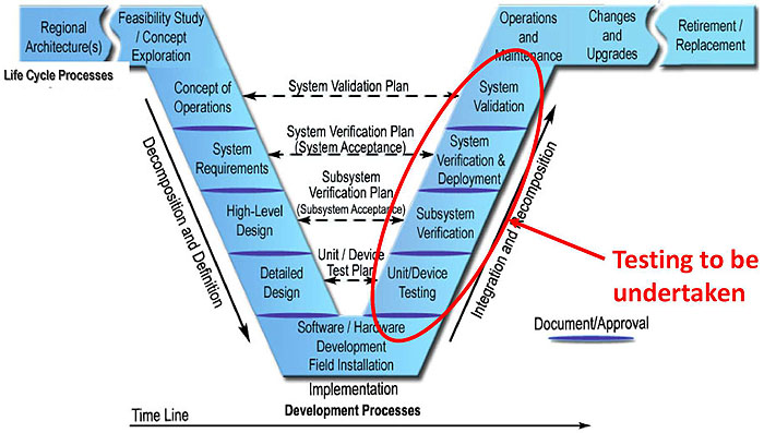
(Extended Text Description: Author's relevant description: This graphic describes the system life cycle. The system life cycle consists of multiple life cycle processes that can be divided into two major processes. On the left side of the "V" model is the "decomposition and definition" process and on the right hand side is the "integration and recomposition" process. The "decomposition and definition" process (also called the top-down process), consists of the life cycle processes from regional architectures, ConOps, system requirements, system design, to field deployment. The "integration and recomposition" process, (also called the bottom-up process) consists of the steps from field deployment, unit testing, system verification and validation, to operation and maintenance, change management, and all the way to system retirement.
Users' needs and requirements are normally developed during the decomposition and definition process as shown on the left side of the "V" chart, and testing takes place during the integration and recomposition process as shown on the right side of the "V" chart.
As for the testing to be undertaken, each of the testing phases includes the following:
- Unit/Device Testing is to test a standalone device
- Subsystem Verification is to test a system interface and its immediate environment, typically under laboratory or central environment
- System Verification & Deployment is to test the entire system interface, including the TMC software.
- System Validation is to ensure the system satisfies all user needs.
)
Source: https://www.fhwa.dot.gov/cadiv/segb/
Slide 13:
Learning Objective #1
System Life Cycle (cont.)
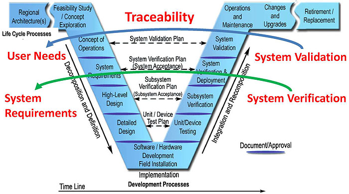
(Extended Text Description: Author's relevant description: This graphic describes traceability during the verification and validation process by illustrating the system life cycle from a different perspective. On the left side of the "V" model, we have "user needs" and "system requirements" defined in the earlier stages of the system life cycle. On the right side, we have "system verification" and "system validation" defined in the later stage of the system life cycle. In order to determine if the user's needs and requirements are fulfilled, the system under test needs to be verified against system requirements, and user needs are validated through the system validation process. "Traceability" is a tool to help determine the system correctness and other attributes such as completeness, accuracy, consistency and testability. Traceability needs to be achieved at many levels throughout the system life cycle. In short, a system that being acquired or developed must be testable or verifiable, and that's why traceability plays such a big role in testing.)
Source: http://www.fhwa.dot.gov/cadiv/segb/
Slide 14:
Learning Objective #1
Verification Methods
- The testing process determines whether the system conforms to the requirements and whether it satisfies its intended use and user needs (IEEE-829).
-
This determination may be based on one or more of the following methods:
- Inspection
- Demonstration
- Analysis
- Testing
Slide 15:
Learning Objective #1
Testing Process
-
According to IEEE 829, the testing process provides an objective assessment of the system products throughout each project's life cycle:
- At the completion of each development iteration
- At installation and go-live
- During operations and maintenance
- System upgrades
- System replacement
Slide 16:
Learning Objective #1
Testing Process (cont')
Three major stages:
-
Step 1 - Test Planning
- Test plan
-
Step 2 - Test Documentation Preparation
- Test design
- Test case
- Test procedure
-
Step 3 - Test Execution and Reporting
- Test report
Slide 17:
Learning Objective #1
Testing Process and System Life Cycle

(Extended Text Description: Author's relevant description: This graphic illustrates how the testing processes relate to the system life cycle. Test planning occurs at the beginning of the system life cycle when the user's needs and requirements are being developed. Writing test plans usually takes place in this stage. Test documentation preparation such as performing test design and developing test cases and test procedures occurs during the system design phase. Please note the difference between test plans and test documentation. Test plans are developed at the beginning of the testing process for test planning purpose and describe the technical and management approach to be followed for testing a system. Test documentation including test cases and test procedures is prepared while a test design is being performed, which typically occurs after its associated test plan is written. If an ITS device is acquired, the test plans and test documentation should be developed prior to the delivery of the device. The test plans and test documents can then be used for acceptance testing at the delivery of the device and after the field installation. Test execution and reporting is conducted at the completion of system development or after the ITS device is delivered. The testing takes place at multiple levels as discussed earlier. In addition to the unit testing, it also includes the testing performed at the subsystem and system levels and during operations, maintenance, and system upgrades. During this process, revisions to the test plan and test documentation prepared in the earlier stages may be required.)
Source: http://www.fhwa.dot.gov/cadiv/segb/
Slide 18:

Slide 19:
Learning Objective #1
Which of the following Statements is not correct?
Answer Choices
- Requirements can be verified by inspection, demonstration, analysis, and testing of the system products.
- The testing process provides an objective assessment of system products throughout the system life cycle.
- Test documentation needs to be prepared only at the completion of system development.
- Development of test plans can begin as soon as the system ConOps is being developed.
Slide 20:
Learning Objective #1
Review of answers
 a) Requirements can be verified by inspection, demonstration, analysis and testing of the system products.
Incorrect. The statement is true.
 b) The testing process provides an objective assessment of system products throughout the system life cycle.
Incorrect. The statement is true.
Slide 21:
Learning Objective #1
Review of answers (cont.)
 c) Test documentation needs to be prepared only at the completion of system development.
Correct. The statement is not correct.
The test documentation is typically prepared at the system design stage and not after the system development is complete.
 d) Development of test plans can begin as soon as the system ConOps is being developed.
Incorrect. The statement is true. It is worth noting that development of test plans may begin early in the system life cycle, but they cannot be finalized until the requirements are fully developed.
Slide 22:
Summary of Learning Objective #1
Describe within the context of a testing lifecycle the role of a test plan and the testing to be undertaken
- Discussed the purpose of testing a CCTV system
- Reviewed the concept of system life cycle and testing to be undertaken
- Reviewed verification methods
- Discussed the testing process in relation to the system life cycle
Slide 23:
Learning Objective #2 — Recognize the purpose, structure, and content of well-written test plans
- Purpose of test plans
- What is a test plan?
-
Structure of test plans
- Master Test Plan (MTP)
- Level Test Plan (LTP)
- Content of test plans
Slide 24:
Learning Objective #2
Purpose of Test Plans
-
Provide an overall document for:
- Test planning
- Test management
- Identify test activities and efforts
- Set objective for each test activity
- Identify the risks, resources, and schedule
- Determine requirements for test documentation
Slide 25:
Learning Objective #2
What is a Test Plan?
IEEE 829 defines Test Plan as:
- A document describing the scope, (technical and management) approach, resources, and schedule of intended test activities.
- It identifies test items, the features to be tested, the testing tasks, who will do each task, and any risks requiring contingency planning.
- The document may be a Master Test Plan (MTP) or a Level Test Plan (LTP).
Test Plan is not defined in NTCIP standards!
Slide 26:
Learning Objective #2
Structure of Test Plans

(Extended Text Description: Author's relevant description: This graphic shows the relationship between a Master Test Plan and multiple Level Test Plans, and how the test plans can be structured for a project. A master test plan is an overall test planning document that consists of three test levels including unit test, subsystem integration test, and system acceptance test. For each test level, a separate test plan is generally required because each level requires different resources, methods, and environments.)
A Master Test Plan may not always be required!
Slide 27:
Learning Objective #2
An Example of ITS Test Plans
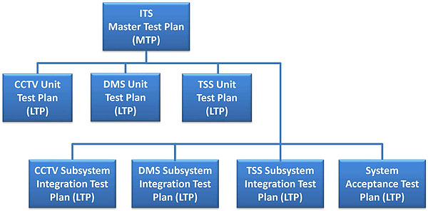
(Extended Text Description: Author's relevant description: This graphic shows an example of an ITS Master Test Plan and multiple Level Test Plans that includes subcomponents of the ITS systems. The overall ITS includes multiple subsystems such as CCTV, DMS, and TSS (transportation sensor systems). The level testing will include unit testing and subsystem testing for each system component and subsystem. It will also include the system acceptance testing for the overall system with all the system components included.)
Slide 28:
Learning Objective #2
An Example of CCTV Test Plans
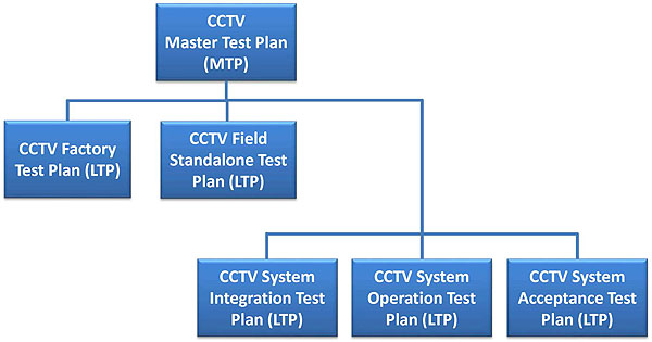
(Extended Text Description: Author's relevant description: This graphic shows an example of CCTV testing that includes a Master Test Plan and multiple Level Test Plans for a CCTV system. In this example, only CCTV system is tested at different levels such as factory test, field standalone test, system integration test, system operation test, and system acceptance test. The factory test and field standalone test are the testing at unit level and only limited system interface will be tested in a simulated environment. System integration testing is to test the entire CCTV system in the real environment including the actual field conditions and central system. A system operational test may also be needed for testing the CCTV system in an extended period such as 20 or 30 days prior to final system acceptance test. The system acceptance test is to focus on the fitness for use and validate the system is implemented per the user's needs.)
Slide 29:
Learning Objective #2
Master Test Plan Outline (IEEE 829)
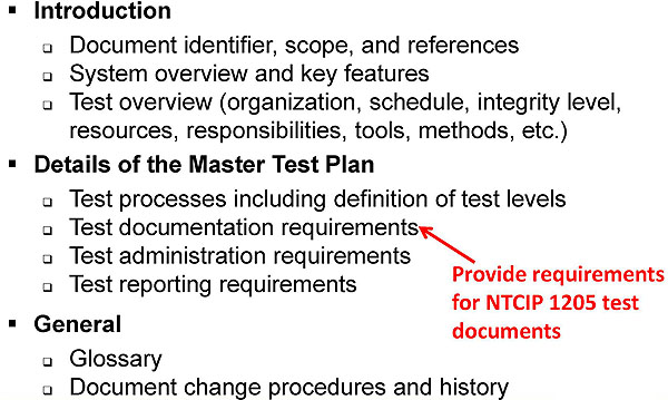
(Extended Text Description: This graphic shows that if an MTP is developed, the MTP needs to list the requirements for test documentation. For the NTCIP 1205 testing, requirements for test documents may include requirements test case traceability matrix, test cases, and test procedures. The bulleted list includes the following:
-
Introduction
- Document identifier, scope, and references
- System overview and key features
- Test overview (organization, schedule, integrity level, resources, responsibilities, tools, methods, etc.)
-
Details of the Master Test Plan
- Test processes including definition of test levels
- Test documentation requirements
- Test administration requirements
- Test reporting requirements
-
General
- Glossary
- Document change procedures and history
The text to the side, "Provide requirements for NTCIP 1205 test documents" has an arrow pointing to "Test documentation requirements.")
Slide 30:
Learning Objective #2
Level Test Plan Outline (IEEE 829)

(Extended Text Description: This graphic shows that a test traceability matrix may be also included in the level test plan. For testing NTCIP 1205, this can be the requirements test case traceability matrix that is used to further develop test cases and test procedures during the test design. The bulleted list includes the following:
-
Introduction
- Document identifier, scope, and references
- Level in the overall sequence
- Test classes and overall test conditions
-
Details for the level of test plan
- Test items and their identifiers
- Test Traceability Matrix
- Features to be tested
- Features not to be tested
- Approach
- Item pass/fail criteria
- Suspension criteria and resumption requirements
- Test deliverables
The text to the side, "For developing test cases and test procedures for NTCIP 1205" has an arrow pointing to "Test Traceability Matrix.")
Slide 31:
Learning Objective #2
Level Test Plan Outline (cont.)
-
Test Management
- Planned activities and tasks; test progression
- Environment/infrastructure
- Responsibilities and authority
- Interfaces among the parties involved
- Resources and training
- Schedules, estimates, and costs
- Risk(s) and contingency(s)
Slide 32:
Learning Objective #2
Level Test Plan Outline (cont.)
-
General
- Quality assurance procedures
- Metrics for specific measures
- Test coverage (% of requirements tested)
- Glossary
- Document change procedures and history
Slide 33:

Slide 34:
Learning Objective #2
Develop a Sample CCTV Unit Test Plan
Refer to the Student Supplement for details.
-
Level in the overall sequence
- Show the CCTV unit testing in the overall test hierarchy -a diagram will be helpful
-
Test classes and overall test conditions
- Describe the attributes of the CCTV camera unit test -Pan-Tilt-Zoom (PTZ), presets, focus, iris, alarms & zones
- Positive testing - valid input values
- Negative testing - invalid values for error processing
- Boundary testing - input values just above, just below, and just on each limit
Slide 35:
Learning Objective #2
Develop a Sample CCTV Unit Test Plan (cont')
-
Test Items
- CCTV camera model, make, firmware version, etc.
- Reference to the CCTV user manual, operations guide, installation guide, etc.
- Transfer from other environments to the test environment
-
Test Traceability Matrix
- Provide a list of requirements and corresponding test cases or procedures - Requirements to Test Case Matrix defined in NTCIP 8007
- Or a reference to a larger Test Traceability Matrix for all levels of test
Slide 36:
Learning Objective #2
Develop a Sample CCTV Unit Test Plan (cont')
-
Features to be tested and not to be tested
- CCTV features based on project-specific requirements - Requirements Traceability Matrix (RTM)
- Remote control functions may not be tested
-
Test Approach
- Overall approach for the unit testing
- Commonly combined in a Test Matrix with features to be tested
- Test methods - black box, white box, analysis, and inspection
Slide 37:
Learning Objective #2
Features to be Tested - CCTV Configuration

(Extended Text Description: This graphic illustrates an example RTM from A317b training module for CCTV configuration. On the left side of the RTM, it shows some of the project requirements for configuring a CCTV camera and on the right side of the table, it shows NTCIP 1205 dialogs and objects that are associated with each requirement. The features to be tested for the CCTV unit resting will be NTCIP objects shown on this RTM. These objects will need to be included in the unit test plan, typically included in the test matrix. The table contains the content below:
| RQ. ID | Requirement | Dialog | Object Reference and Title (NTCIP 1205 Section 3) |
|---|---|---|---|
| 3.3.1 | Data Exchange Requirements for Managing Configuration | D.3 Generic SNMP SET Interface | |
| 3.3.1.1 | Configure Range Maximum presets | 3.2.1 | rangeMaximumPreset |
| 3.3.1.2 | Configure Range-Pan Left Limit | 3.2.2 | rangePanLeftLimit |
| 3.3.1.3 | Configure Range-Pan Right Limit | 3.2.3 | rangePanrightLimit |
| 3.3.1.4 | Configure Range Pan Home Position | 3.2.4 | rangePanHomePosition |
| 3.3.1.5 | Configure True North Offset | 3.2.5 | rangeTrueNorthOffset |
| 3.3.1.6 | Configure Range Iris Limit | 3.2.10 | rangIirisLimit |
| 3.3.1.13 | Configure Timeout Pan | 3.3.1 | timeOurPan |
| 3.3.1.16 | Configure Timeout Focus | 3.3.4 | timeOutFocus |
| 3.3.1.19 | Configure Label Table | 3.11.2 | labelTable |
The text at the bottom "Features to be Tested" has an arrow pointing to the right column, which is outlined in red, starting with 3.2.1 through 3.11.2.)
Slide 38:
Learning Objective #2
Features to be Tested - Camera Control
| Rq. ID | Requirement | Dialog | Object Reference and Title NTCIP 1205 |
|---|---|---|---|
| 3.3.2 | Camera Control | D.3 Generic SNMP SET Interface | |
| 3.3.2.1 | Preset Go to Position | 3.4.1 presetGotoPosition | |
| 3.3.2.2 | Go to a Stored Position | 3.4.2.presetStorePosition | |
| 3.3.2.6 | Zoom Operation |
3.2.8 rangeZoomLimit 3.3.3 timeoutZoom 3.3.3 positionZoomLens |
|
| 3.3.2.4 | Camera Position Horizontally (Pan) |
3.2.2 rangePanLeftLimit 3.2.4 rangePanHomePosition 3.2.11 rangeMinimumPanStepAngle 3.3.1 timeoutPan 3.5.1 positionPan 3.2.3 rangePanRightLimit 3.2.4 rangePanHomePosition 3.2.11 rangeMinimumPanStepAngle 3.3.1 timeoutPan |
|
Slide 39:
Learning Objective #2
Features to be Tested - CCTV Monitoring
| Rq. ID | Requirement | Dialog | Object Reference and Title NTCIP 1205 Section 3 |
|---|---|---|---|
| 3.3.3 | Status condition within the device | D.1 Generic SNMP GET Interface | |
| 3.3.3.2 | Temperature | 3.7.5 alarmTemperatureCurrentValue | |
| 3.3.3.2 | Pressure |
3.7.6 alarmPressureHighLowThreshold 3.2.7 alramPressureCurrentValue |
|
| 3.3.3.2 | Washer fluid |
3.7.8 alarmWasherFluidHighLowThreshold 3.2.9 alarmWasherCurrentValue |
|
| 3.3.3.3 | ID Generator | 3.11 cctv label Objects | |
Note that these are only examples and do not include all NTCIP objects that are required for the project. All required objects included in the project RTM will need to be included in the test plans.
Slide 40:

Slide 41:
Learning Objective #2
Which of the following is included in a Level Test Plan (LPT) but not in a Master Test Plan (MTP)?
Answer Choices
- Test scope
- Test processes
- Test resources and responsibilities
- Test Traceability Matrix
Slide 42:
Learning Objective #2
Review of answers
 a) Test scope
Incorrect! Included in both the LTP and MTP.
 b) Test processes
Incorrect! Included in the MTP only.
 c) Test resources and responsibilities
Incorrect! Included in both the LTP and MTP.
 d) Test Traceability Matrix
Correct! Test Traceability Matrix is only included in the LTP, but not in the MTP.
Slide 43:
Summary of Learning Objective #2
Recognize the purpose, structure and content of well-written test plans
- Discussed the definition of Test Plan per IEEE 829
- Identified the difference between the Master Test Plan (MTP) and the Level Test Plan (LTP), and when and how to use them
- Discussed the structure and content of the MTP and LTP
Slide 44:
Learning Objective #3 — Describe test documentation for NTCIP 1205
- Overview of test documentation
- Understand the difference between test plans and test documentation
- Overview of a test design and the relationships between test plans, test design, test cases, and test procedures
Slide 45:
Learning Objective #3
Test Documentation
According to IEEE 829:
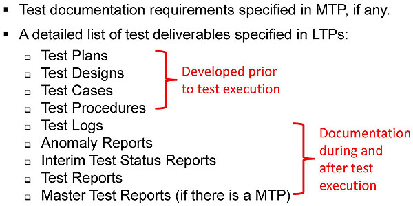
(Extended Text Description: This slide describes the test deliverables/documentation defined in the 2008 version of IEEE 829 standard. Test should not begin until all of the test documents are prepared. The test plans, test design, test cases and test procedures should be well developed and approved for use prior to the test. The rest of test documents are to serve the purpose for test reporting. The bulleted text contains the following:
- Test documentation requirements specified in MTP, if any.
-
A detailed list of test deliverables specified in LTPs:
- Test Plans
- Test Designs
- Test Cases
- Test Procedures
- Test Logs
- Anomaly Reports
- Interim Test Status Reports
- Test Reports
- Master Test Reports (if there is a MTP)
To the right, the text "Developed prior to test execution" relates to Test Plans, Test Designs, Test Cases, and Test Procedures.
To the right, the text "Documentation during and after test execution" relates to Test Logs, Anomaly Reports, Interim Test Status Reports, Test Reports, Master Test Reports (if there is a MTP).)
Slide 46:
Learning Objective #3
Test Documentation prior to Test Execution

(Extended Text Description: Author's relevant description: This graphic illustrates the test documentation required prior to conducting the testing. In this diagram, three levels of tests are used. They are the unit test, subsystem integration test, and system acceptance test. This diagram only expands the Unit Test Plan to include the test documents associated with the unit testing. The successor documents also apply to all levels of tests. The main step is to develop the test design, which is a document to specify the details of the test approach for features to be tested and identifying the associated tests, commonly by including the organization of the tests into groups. Test cases and test procedures are generally developed during test design.)
Slide 47:
Learning Objective #3
Test Documentation during and after Test Execution
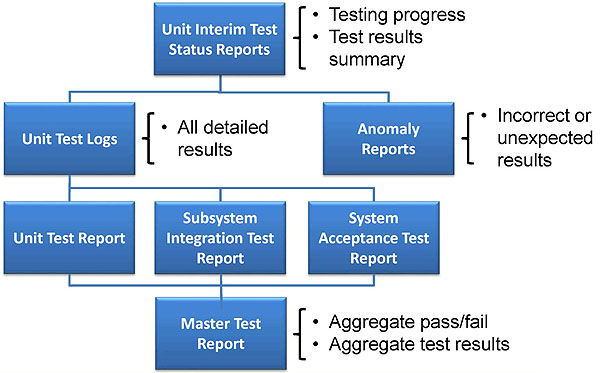
(Extended Text Description: Author's relevant description: This graphic lists the test documentation required during and after the testing. This diagram still uses the three levels of test as used in last slide. Predecessor documents such as Unit Interim Test Status Reports, Unit test logs and anomaly reports also apply to all levels of test. In this case, the other levels of test are subsystem integration test report and system acceptance test report.)
Slide 48:
Learning Objective #3
Understand the Difference between Test Plans and Test Documentation
-
Test plans
- Defines the test documents required
- Developed earlier than test documents
-
Test documentation includes all information that is to be delivered by test activities:
- Test documents - test cases, test procedures, test reports, etc.
- Test input and output data
- Test tools
Slide 49:
Learning Objective #3
Test Design
IEEE 829 defines a test design as a test document that:
- Specifies the details of the test approach
-
Identifies the features to be tested by this design
- Requirements Test Case Traceability Matrix
-
Identifies the associated tests - commonly including the organization of the tests into groups
- Test cases
- Test procedures
Slide 50:
Learning Objective #3
Requirements Test Case Traceability Matrix
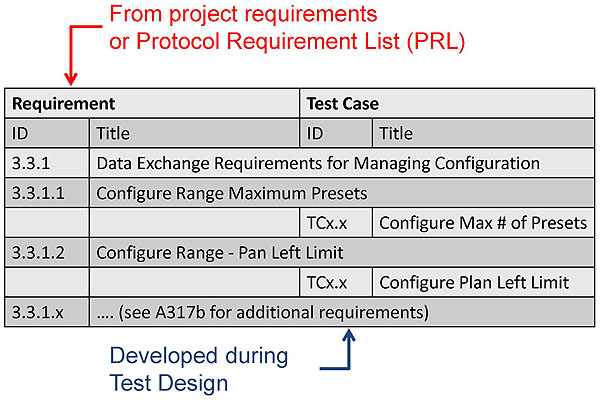
(Extended Text Description: This graphic shows the format of the Requirements Test Case Traceability Matrix that is defined in NTCIP 8007 and is commonly used in the NTCIP standards. The left side of the matrix should list all the project requirements that can be traced to one or more test cases listed on the right side of the matrix. Each requirement and test case are given an unique ID number. The requirements can be obtained from the project specifications or a Project Requirement List. This slide shows some of the data exchange requirements in an example PRL used in the A317b training module. The slide contains the following table:
The text "From project requirements or Protocol Requirement List (PRL)" points to "Requirement."
| Requirement | Test Case | ||
|---|---|---|---|
| ID | Title | ID | Title |
| 3.3.1 | Data Exchange Requirements for Managing Configuration | ||
| 3.3.1.1 | Configure Range Maximum Presets | ||
| TCx.x | Configure Max # of Presets | ||
| 3.3.1.2 | Configure Range - Pan Left Limit | ||
| TCx.x | Configure Plan Left Limit | ||
| 3.3.1.x | .... (see A317b for additional requirements) | ||
The text "Developed during Test Design" points to ".... (see A317b for additional requirements).")
Slide 51:
Learning Objective #3
Relationship between Test Plan, Test Design, Test Case, and Test Procedure
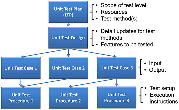
(Extended Text Description: Author's relevant description: This graphic shows the relationship between Test Plan, Test Design, Test Case, and Test Procedure using the unit test as an example. For each level test plan, it directly relates to the following test documents: One test design document, One or multiple test cases, and One or multiple test procedures.)
Slide 52:
Learning Objective #3
Relationship between Test Plan, Test Design, Test Case, and Test Procedure (cont.)
-
Test Plan vs. Test Design
- Only one test design for each test plan
-
Test Design vs. Test Case
- One test design may be associated with multiple test cases
- Any one test case is associated with only one test design
-
Test Case vs. Test Procedure
- One test case may be associated with multiple test procedures, and vice versa - IEEE 829
- For simple devices (e.g. CCTV), NTCIP combines test case and test procedure
Slide 53:

Slide 54:
Learning Objective #3
Which of the following is part of test documentation?
Answer Choices
- Test Data
- Test Plans
- Requirement Test Case Traceability Matrix
- All of the above
Slide 55:
Learning Objective #3
Review of answers
 a) Test Data
Incorrect! Included in test deliverables, so it is part of the test documentation.
 b) Test Plans
Incorrect! Included in test deliverables, so it is part of the test documentation.
 c) Requirement Test Case Traceability Matrix
Incorrect! Included in both LTP and test design, so it is part of the test documentation.
 d) All of the above
Correct! All of the above are part of test documentation.
Slide 56:
Summary of Learning Objective #3
Describe test documentation for NTCIP 1205
- Reviewed test deliverables/documentation
- Discussed the difference between test plans and test documentation
- Reviewed the test design and the relationships between the test plan, test design, test cases, and test procedures
Slide 57:
Learning Objective #4 — Describe the application of a good test plan to a CCTV system based on NTCIP 1205 Standard using a sample Requirements to Test Case Traceability Table
- Describe the basis of a CCTV system and its test environment
- Identify key elements of the NTCIP 1205 standard that are relevant to the testing
- Develop sample test documents including test design, test cases, and test procedures
Slide 58:
Learning Objective #4
Basis of a CCTV System
CCTV Field Hardware
- Camera and enclosure
- Lens assembly - focus, iris
- Pan/Tilt assembly
- Camera control receiver
- Equipment cabinet
- Communications device
- Accessories - camera power supply, wiper, heater, washer, blower, environmental sensor, etc.
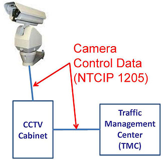
(Extended Text Description: Author's relevant description: This graphic describes the basis of a CCTV system and indicates that NTCIP 1205 only applies to the camera control which does not include the video display function and video format.)
Slide 59:
Learning Objective #4
CCTV Camera Test Environment for Unit Testing
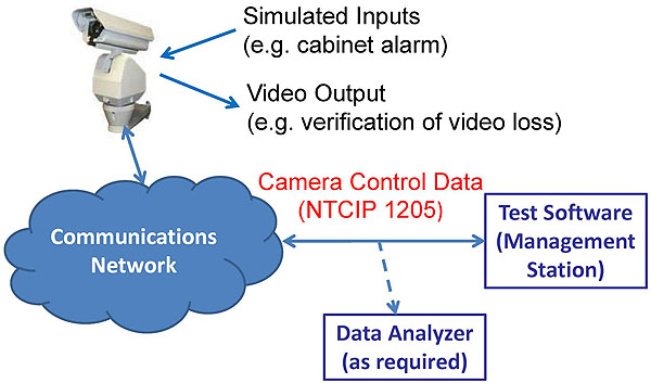
(Extended Text Description: Author's relevant description: This graphic illustrates a typical CCTV camera test environment using the unit test as an example. For NTCIP testing, the test CCTV camera is required to be connected to a test software installed on a management station. A data analyzer may be used to capture the data exchanged between the camera and the management station. Simulated inputs (such as cabinet door alarm) may be used if camera itself is not connected to an equipment cabinet. Whether a cabinet is required or not for testing, it is dependent on the project requirements and the test plan developed by the agency. Video output will need to be monitored on a video monitor so that loss of video image can be verified. The communication network can be serial or Ethernet network depending on the requirements of the project.)
Slide 60:
Learning Objective #4
Identify Key Elements of NTCIP 1205
What are included in NTCIP 1205?
-
CCTV Management Information Base (MIB)
- CCTV Objects (range, timeout, preset, position, system feature, alarm, input, output, zone, label, onscreen menu)
-
Conformance Groups
- CCTV Configuration
- Extended Functions
- Motion Control
- On-screen Menu Control
Slide 61:
Learning Objective #4
Identify Key Elements of NTCIP 1205 (cont.)
What are NOT included in NTCIP 1205, but required for developing test documents?

(Extended Text Description: This graphic describes the key elements that are required for developing test plans and test documents, but not included in NTCIP 1205. The graphic also illustrates that user needs, requirements, dialogs, PRL ad RTM are included in training modules A317a and A317b. The bulleted list contains the following:
- User Needs
- Requirements
- Dialogs
- Protocol Requirements List (PRL)
- Requirements Traceability Matrix (RTM)
- Requirements Test Case Traceability Matrix (RTCTM)
- Test Cases
- Test Procedures
The text at the side, "Included in A317a & A317b modules" refers to User Needs, Requirements, Dialogs, Protocol Requirements List (PRL), and Requirements Traceability Matrix (RTM).)
Slide 62:
Learning Objective #4
Develop Test Documents - Test Design
Develop a Requirements Test Case Traceability Matrix (RTCTM)
- The main purpose of Test Design is to identify the features to be tested by a particular test (e.g. unit test)
- The features to be tested are included in the RTCTM
- Based on a Requirements Traceability Matrix (RTM)
Slide 63:
Learning Objective #4
An example of RTM from A317b module
| Rq. ID | Requirement | Dialog | Object Reference and Title (NTCIP 1205 Section 3) |
|---|---|---|---|
| 3.3.2 | Camera Control | D.3 Generic SNMP SET Interface | |
| 3.3.2.1 | Preset Go to Position | 3.4.1 presetGotoPosition | |
| 3.3.2.2 | Go to a Stored Position | 3.4.2.presetStorePosition | |
| 3.3.2.6 | Zoom Operation |
3.2.8 rangeZoomLimit 3.3.3 timeoutZoom 3.3.3 positionZoomLens |
|
| 3.3.2.4 | Camera Position Horizontally (Pan) |
3.2.2 rangePanLeftLimit 3.2.4 rangePanHomePosition 3.2.11 rangeMinimumPanStepAngle 3.3.1 timeoutPan 3.5.1 positionPan 3.2.3 rangePanRightLimit 3.2.4 rangePanHomePosition 3.2.11 rangeMinimumPanStepAngle 3.3.1 timeoutPan |
|
Slide 64:
Learning Objective #4
Develop a Requirements Test Case Traceability Matrix (RTCTM)
| Requirement | Test Case | ||
|---|---|---|---|
| ID | Title | ID | Title |
| 3.3.2 | Camera Control | ||
| 3.3.2.1 | Preset Go to Position | ||
| 3.3.2.2 | Move Camera to a Stored Position | ||
| C3.01 | Preset Position | ||
| 3.3.2.3 | Zoom Operation | ||
| C3.05 | Delta Zoom Motion | ||
| C3.06 | Absolute Zoom Motion | ||
| C3.07 | Continuous Zoom Motion with Timeout | ||
| C3.08 | Continuous Zoom Motion with Stop | ||
Slide 65:
Learning Objective #4
Develop a Requirements Test Case Traceability Matrix (RTCTM) (cont.)
| Requirement | Test Case | ||
|---|---|---|---|
| ID | Title | ID | Title |
| 3.3.2 | Camera Control | ||
| ... | ... | ||
| ... | ... | ||
| 3.3.2.4 | Camera Position Horizontally (Pan) | ||
| C3.11 | Delta Pan Motion | ||
| C3.12 | Absolute Pan Motion | ||
| C3.13 | Continuous Pan Motion with Timeout | ||
| C3.14 | Continuous Pan Motion with Stop | ||
Slide 66:
Learning Objective #4
Develop Test Documents - Test Case
Use "C3.01 Preset Position" as an example
-
Test Case Identifier
- C3.01
-
Test Case Title
- Preset Position
- Test Case Description
-
Variables
- input and output values and timing are included in test procedures
- Pass/Fail Criteria
Slide 67:
Learning Objective #4
Develop Test Documents - Test Case (cont.)
| Test Case: C3.01 | Title: | Preset Position | |
|---|---|---|---|
| Description: | This test case stores and moves the camera to preset positions | ||
| Variables: | Max_Preset | From Project Requirements | |
| Preset_Speed | From the Test Plan | ||
| Preset_Pan_Position1 | From the Test Plan | ||
| Preset_Pan_Position2 | From the Test Plan | ||
| Preset_Tilt_Position1 | From the Test Plan | ||
| Preset_Tilt_Position2 | From the Test Plan | ||
| Pass/Fail Criteria: | The Device Under Test (DUT) shall pass every verification step included within the Test Case in order to pass the Test Case | ||
Slide 68:
Learning Objective #4
Develop Test Documents - Test Procedure
Use "C3.01 Preset Position" as an example
-
Test Procedure Identifier
- NTCIP combines Test Procedure with Test Case
- Inputs, outputs, and special requirements
- Ordered description of the steps to be taken to execute the test case
-
Keywords
- Defined in NTCIP 8007
-
Test results
- Pass or Fail
Slide 69:
Learning Objective #4
Develop Test Documents - Test Procedure (cont.)
Continued after the test case
| Step | Test Procedure | Results |
|---|---|---|
| 1 |
CONFIGURE: Determine a preset position for the camera between 0 and rangeMaximumPreset.0 (per the project requirement). RECORD this information as: >>Max_Preset |
|
| 2 | SET-UP: if Max_Preset is less than 2, then EXIT | |
| 3 |
GET the following object: >>rangeMaximumPreset.0 |
Pass / Fail |
| 4 | SET-UP: VERIFY that the RESPONSE VALUE is equal to Max_Preset; otherwise, EXIT. |
Slide 70:
Learning Objective #4
Develop Test Documents - Test Procedure (cont.)
| Step | Test Procedure | Results |
|---|---|---|
| 5 |
CONFIGURE: Determine the following value from the test plan. RECORD the information as: >>Preset_Speed >>Preset_Pan_Position1 >>Preset_Pan_Position2 >>Preset_Tilt_Position1 >>Preset_Tilt_Position2 |
|
| 6 |
SET the following objects to the values shown: >>positionPan.0 = 02 Preset_Speed Preset_Pan_Position1 >>postionTilt.0 = 02 Preset_Speed Preset_Tilt_Position1 |
Pass / Fail |
| 7 | VERIFY that camera is in position 1. | Pass / Fail |
| 8 | SET presetStorePosition.0 to 1 | Pass / Fail |
Slide 71:
Learning Objective #4
Develop Test Documents - Test Procedure (cont.)
| Step | Test Procedure | Results |
|---|---|---|
| 9 |
SET the following objects to the values shown: >>positionPan.0 = 02 Preset_Speed Preset_Pan_Position2 >>postionTilt.0 = 02 Preset_Speed Preset_Tilt_Position2 |
Pass / Fail |
| 10 | VERIFY that camera moved to position 2. | Pass / Fail |
| 11 | SET presetStorePosition.0 to 2 | Pass / Fail |
| 12 | SET presetGotoPosition.0 to 1 | Pass / Fail |
| 13 | VERIFY that camera moved in position 1. | Pass / Fail |
| 14 | GET presetPositionQuery.0 | Pass / Fail |
| 15 | VERIFY that RESPONSE VALUE = 1 | Pass / Fail |
| 16 | SET presetGotoPosition.0 to 2 | Pass / Fail |
Slide 72:
Learning Objective #4
Develop Test Documents - Test Procedure (cont.)
| Step | Test Procedure | Results | |
|---|---|---|---|
| 17 | VERIFY that camera moved in position 2. | Pass / Fail | |
| 18 | GET presetPositionQuery.0 | Pass / Fail | |
| 19 | VERIFY that RESPONSE VALUE = 2 | Pass / Fail | |
| Test Case Results | |||
| Tested By: | Date Tested: | Pass / Fail | |
| Test Case Notes: | |||
Slide 73:

Slide 74:
Learning Objective #4
Which is a test document included in NTCIP 1205?
Answer Choices
- Protocol Requirements List (PRL)
- Requirements Traceability Matrix (RTM)
- Requirements Test Case Traceability Matrix (RTCTM)
- None of the above
Slide 75:
Learning Objective #4
Review of answers
 a) Protocol Requirements List (PRL)
Incorrect, PRL is not a test document and not included in NTCIP1205
 b) Requirements Traceability Matrix (RTM)
Incorrect, RTM is not a test document and not included in NTCIP 1205
 c) Requirement Test Case Traceability Matrix (RTCTM)
Incorrect, RTCTM is a test document, but not in NTCIP 1205
 d) None of the above
Correct! None of the above are correct answers
Slide 76:
Summary of Learning Objective #4
Describe the application of a good test plan to a CCTV system based on NTCIP 1205 Standard using a sample Requirements to Test Case Traceability Table
- Reviewed the basis of a CCTV system and its test environment
- Identified key elements of the NTCIP 1205 standard that are relevant to the testing
- Developed sample test documents including test design, test cases, and test procedures
Slide 77:
Learning Objective #5 — Describe test tools and test conditions for NTCIP 1205
- NTCIP test tools and equipment
- Address the consequences of positive and negative testing
- Address the consequences of testing boundary conditions
- Understand the complexity of NTCIP testing
Slide 78:
Learning Objective #5
NTCIP Test Tools and Equipment
- Review of NTCIP test environment
- Minimum requirements for test tools and equipment
- Types of NTCIP test tools
Slide 79:
Learning Objective #5
Review of NTCIP Test Environment
-
Device Under Test (DUT)
- NTCIP device that is the object of testing
- Controller, CCTV camera, DMS, etc.
-
"Certified" Test Software
- Approved for use prior to the testing
-
Data Analyzer
- Capture data exchanged
- Use for in-depth analysis when anomalies occur
-
Communication network
- Ethernet, serial (RS232/RS422/RS485), wireless, etc.
Slide 80:
Learning Objective #5
Review of NTCIP Test Environment (cont.)

(Extended Text Description: Author's relevant description: Similar to the graphic on slide 59, this graphic illustrates a typical CCTV camera test environment using the unit test as an example.)
Slide 81:
Learning Objective #5
Minimum Requirements for Test Tools
- Capable of performing tests for conformance to specific NTCIP information level standards
- Support for communication testing such as SNMP
- Scripting features to support automated testing
- Support various protocols including PPP, PMPP, TCP/IP, etc.
- Support a wide variety of media including Ethernet and Serial
Slide 82:
Learning Objective #5
Types of NTCIP Test Tools
Passive Test Tools
- Used as data analyzer
- Monitor data exchange only
- Live data capture
- Do NOT provide or respond to an ITS device stimulus
-
Examples
- Serialtest
- Ethereal
- Other protocol analyzers
Slide 83:
Learning Objective #5
Types of NTCIP Test Tools (cont')
Active Test Tools
- Used as main test software
- Provide a means to send message to DUT and await response
-
Limitations
- Do NOT support all objects in NTCIP such as proprietary logical blocks
- Do NOT support sophisticated communication testing, e.g. communication load testing
- Special purpose software needs to be developed to perform additional testing
Slide 84:
Learning Objective #5
Types of NTCIP Test Tools (cont.)
Examples of Active NTCIP Test Software
- DeviceTester
- NTCIP Exerciser
- Ntester
- SimpleTester
Slide 85:
Learning Objective #5
Address the Consequences of Positive and Negative Testing
-
Positive testing
- Valid input values
- DUT should process successfully
-
Negative testing
- Invalid input values, dialogs, or data exchange sequence
- DUT should NOT process
- DUT should remain in normal operation
-
DUT should provide an appropriate error processing
- For example, DUT responds with an error message when the test moves camera to an invalid zone
Slide 86:
Learning Objective #5
Address the Consequences of Testing Boundary Conditions
-
All boundary values should be tested
- just below each limit
- just above each limit
- just on each limit
-
If the boundary value is valid, DUT should:
- Process it successfully and respond accordingly
-
If error conditions occur, DUT should:
- Respond with proper error messages
- Remain in normal operation
- No communications "lock-up"
Slide 87:
Learning Objective #5
Understand the Complexity of NTCIP Testing
-
Testing is a complex process
- Test planning
- Test documentation preparation
- Test execution
- Test result reporting
-
All NTCIP objects required by the project should be tested
- Perform sampling of valid inputs
- Test boundary conditions
- Selectively test error conditions for critical functions
Slide 88:
Learning Objective #5
Understand the Complexity of NTCIP Testing (cont.)
-
Progression testing
- Testing new and corrected features as a result of new releases of software
-
Regression testing
- Testing to ensure that no unintended changes have occurred
- Test agency will determine the extent of tests that must be repeated
- At a minimum, regression testing should be done for all the software affected by the test failure
Slide 89:

Slide 90:
Learning Objective #5
Which of the following statements is correct?
Answer Choices
- Data analyzer is an active test tool and can be used to respond to the DUT's request
- All possible permutations and combinations of valid input values need to be tested
- Performing boundary analysis is not necessary during NTCIP testing
- None of the above
Slide 91:
Learning Objective #5
Review of answers
 a) Data analyzer is an active test tool and can be used to respond to the DUT's request
Incorrect. Data analyzer is a passive test tool and can only be used to monitor the data exchanged between two components.
 b) All possible permutations and combinations of valid input values need to be tested
Incorrect. It is impossible to test all possible permutations and combinations of valid input values; Instead, testing samples within the required range should produce acceptable test results.
Slide 92:
Learning Objective #5
Review of answers
 c) Performing boundary analysis is not necessary during NTCIP testing
Incorrect. Performing boundary analysis with positive and negative range is necessary to verify the DUT's response to all required dialogs and objects.
 d) None of the above
Correct. None of the above are correct answers.
Slide 93:
Summary of Learning Objective #5
Describe test tools and test conditions for NTCIP 1205
- Reviewed the test tools and equipment
- Discussed the consequences of positive and negative testing
- Discussed the consequences of testing boundary conditions
- Discussed the complexity of NTCIP testing
Slide 94:
What We Have Learned
- The testing process determines whether the system conforms to the requirements and whether it satisfies its intended use and user needs.
- Requirements can be verified by inspection, demonstration, analysis and testing of the system products.
- The testing process provides an objective assessment of system products throughout the system lifecycle.
- A test plan is a document that describes the scope, approach, resources and schedule of intended test activities.
- The test plan may be a Master Test Plan or a Level Test Plan.
Slide 95:
What We Have Learned
- A list of test documents delivered at the completion of the test is included in Level Test Plans.
- The details of Requirements Test Case Traceability Matrix are developed as part of test design.
- Test cases define test input and output values.
- Keywords used in test procedures are defined in NTCIP 8007.
- NTCIP test tools include passive and active test tools.
Slide 96:
Resources
- IEEE 829, IEEE Standard for Software Test Documentation, IEEE, 1998 or 2008 version.
- NTCIP 1205 v01.08, National Transportation Communications for ITS Protocol: Object Definition for Closed Circuit Television (CCTV) Camera Control, AASHTO/ITE/NEMA, December 2001 (or Revision Amendment 1, November 2004).
- NTCIP 8007:2008, National Transportation Communications for ITS Protocol: Testing and Conformity Assessment Documentation within NTCIP Standards Publications, v01, AASHTO/ITE/NEMA, May 2008.
Slide 97:
Resources
- NTCIP 9001 Version v04, National Transportation Communications for ITS Protocol, The NTCIP Guide, AASHTO/ITE/NEMA, July 2009.
- Systems Engineering Guidebook for Intelligent Transportation Systems Version 3.0, United States Department of Transportation, November 2009.
- PCB Training Modules Available at stds training.aspx
Slide 98:
