Module 39 - A307a
A307a: Understanding User Needs for Advanced Transportation Controllers Based on ATC 5201 Standard v06
HTML of the PowerPoint Presentation
(Note: This document has been converted from a PowerPoint presentation to 508-compliant HTML. The formatting has been adjusted for 508 compliance, but all the original text content is included, plus additional text descriptions for the images, photos and/or diagrams have been provided below.)
Slide 1:
(Extended Text Description: Welcome - Graphic image of introductory slide. A large dark blue rectangle with a wide, light grid pattern at the top half and bands of dark and lighter blue bands below. There is a white square ITS logo box with words "Standards ITS Training" in green and blue on the middle left side. The word "Welcome" in white is to the right of the logo. Under the logo box is the logo for the U.S. Department of Transportation, Office of the Assistant Secretary for Research and Technology.)
Slide 2:

(Extended Text Description: This slide, entitled "Welcome" has a photo of Ken Leonard, Director, ITS Joint Program Office, on the left hand side, with his email address, Ken.Leonard@dot.gov. A screen capture snapshot of the home webpage is found on the right hand side - for illustration only - from August 2014. Below this image is a link to the current website: www.its.dot.gov/pcb - this screen capture snapshot shows an example from the Office of the Assistant Secretary for Research and Development - Intelligent Transportation Systems Joint Program Office - ITS Professional Capacity Building Program/Advanced ITS Education. Below the main site banner, it shows the main navigation menu with the following items: About, ITS Training, Knowledge Exchange, Technology Transfer, ITS in Academics, and Media Library. Below the main navigation menu, the page shows various content of the website, including a graphic image of professionals seated in a room during a training program. A text overlay has the text Welcome to ITS Professional Capacity Building. Additional content on the page includes a box entitled What's New and a section labeled Free Training. Again, this image serves for illustration only. The current website link is: https://www.its.dot.gov/pcb.)
Slide 3:

Slide 4:
A307a:
Understanding User Needs for Advanced Transportation Controllers Based on ATC 5201 Standard v06
Slide 5:
Instructor

Ralph W. Boaz President
Pillar Consulting, Inc.
San Diego, CA, USA
Slide 6:
Target Audience
- Traffic management and engineering staff
- Traffic Management Center/operations staff
- Traffic signal maintenance staff
- System developers
- Software developers
- Private and public sector users including manufacturers
- Procurement personnel
Slide 7:
Recommended Prerequisites
- I101: Using ITS Standards: An Overview
- A101: Introduction to Acquiring Standards-based ITS Systems
- A102: Introduction to User Needs Identification
- A201: Details On Acquiring Standards-based ITS Systems
- A202: Identifying and Writing User Needs When ITS Standards Do Not Have SEP Content
- A103: Introduction to ITS Standards Requirements Development
- A203: Writing Requirements When ITS Standards Do Not Have
SEP Content
Slide 8:
Recommended Prerequisites (cont.)
- C101: Introduction to the Communications Protocols and Their Uses in ITS Applications
- A207a: Building an ITS infrastructure Based on the ATC 5201 Standard Part 1 of 2
- A207b: Building an ITS infrastructure Based on the ATC 5201
Standard Part 2 of 2
- A208: Using the ATC 5401 Application Programming Interface Standard to Leverage ITS Infrastructures
Slide 9:
Curriculum Path

(Extended Text Description: This slide contains a graphic illustration indicating the sequence of training modules that lead up to this course. Each module is represented by a box with the name of the module in it and arrows showing the logical flow between the modules. There are 12 boxes in total; three rows of 4 boxes. The sequence goes from left to right with the fourth box on the first and second rows having arrows which connect to the first box on the second and third rows respectively. The module titles are as follows: I101: Using ITS Standards: An Overview, A101: Introduction to Acquiring Standards -based ITS Systems, A102: Introduction to User Needs Identification, A201: Details on Acquiring Standards-based ITS Systems, A202: Identifying and Writing User Needs When ITS Standards, Do Not Have SEP Content, A103: Introduction to ITS Standards Requirements Development, A203: Writing Requirements When ITS Standards Do Not Have SEP Content, C101: Intro. to Comm. Protocols and Their Uses in ITS Applications, A207a: Building an ITS Infrastructure Based on the ATC 5201 Standard (Part 1), A207b: Building an ITS Infrastructure Based on the ATC 5201 Standard (Part 2), A208: Using the ATC 5401 Application Programming Interface Standard to Leverage ITS Infrastructures, A307a: Understanding User Needs for Advanced Transportation Controllers (ATC) Based on 5201 Standard v06. The last box is highlighted indicating that it represents the current module in the series.)
Slide 10:
Learning Objectives
- Identify the advantages of transportation controllers based on ATC 5201 Standard v06
- Describe a systems engineering-based ATC specification development process
- Identify and write user needs for ATCs
- Create a concept of operations (ConOps)
Slide 11:
Learning Objective #1: Identify the Advantages of Transportation Controllers Based on ATC 5201 Standard v06
- Discuss the purpose of the ATC 5201 Standard v06
- Identify key elements of the ATC 5201 Standard v06 architecture
- Describe how ATC 5201 Standard v06 works with other ITS standards
Slide 12:
Learning Objective #1
Discuss the Purpose of the ATC 5201 Standard v06

(Extended Text Description: This slide, entitled "Discuss the Purpose the ATC 5201 Standard v06," contains a graphic used to highlight bulleted text in the slide. There is a blue box in the lower right of the slide that appears with an arrow pointing to the slide text "Multi-tasking/multi-application." The box contains the text "When using ATC Application Programming Interface (API) Software." The bulleted text in the slide is as follows:
-
Provide a general purpose field-computing platform for transportation applications that are:
-
Open architecture
- Any manufacturer can build products conforming to the standards
-
Modular
- Reduces maintenance costs
- Increases testability
-
Multi-tasking/multi-application
- Can do multiple things at the same time
- May be used for many purposes
-
Open architecture
)
Slide 13:
Learning Objective #1
Discuss the Purpose of the ATC 5201 Standard v06 (cont.)
-
Provide a general purpose field-computing platform for transportation applications that:
-
Can grow with technology
- Standards allow for evolution within a framework
-
Upgrade for legacy transportation field cabinet systems (TFCSs)
- Get contemporary performance and capabilities using older cabinet architectures
-
Can grow with technology
Slide 14:
Learning Objective #1
Traditional Controllers Run a Single Application Program at a Time
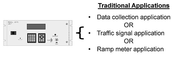
(Extended Text Description: This slide, entitled "Traditional Controllers Run a Single Application Program at a Time," has a graphic of a transportation controller on the left side of the slide, a list of three applications used in transportation controllers on the right side of the slide and a left brace that is used to indicate that the applications on the right may run within the controller on the left. The text to the right reads, Traditional Applications, Data collection application OR Traffic signal application OR Ramp meter application. The controller on the left is rectangular and about 2.5 times as wide as it is tall. There is a small rectangular screen in the upper center of the controller. There are two rectangular key pads (side by side) beneath the screen. To the left of the keypad is an LED with the word "ACTIVE" underneath it. To the left of the LED at mid-height of the controller is a rectangular latch. The upper left portion of the controller has the words "MODEL 2070 UNIT." To the right of the keypads is a toggle switch with the word "AUX" to the left of it and the words "ON" and OFF" above and below it respectively. To the right of the switch and slightly higher is a round knob that has the word "CONTRAST" beneath it. Below the Contrast Knob are two small rectangular connectors arranged vertically. Above the first connector is the word "C50S" below the second connector is the word "C50J." Near the right edge of the controller are two large screws with one located near the top controller and the other located near the bottom of the controller. To the right of the screws is a narrow hinge that runs down the entire height of the controller.)
Graphics: Ralph W. Boaz
Slide 15:
Learning Objective #1
Any ATC Can Run Multiple Application Programs Simultaneously
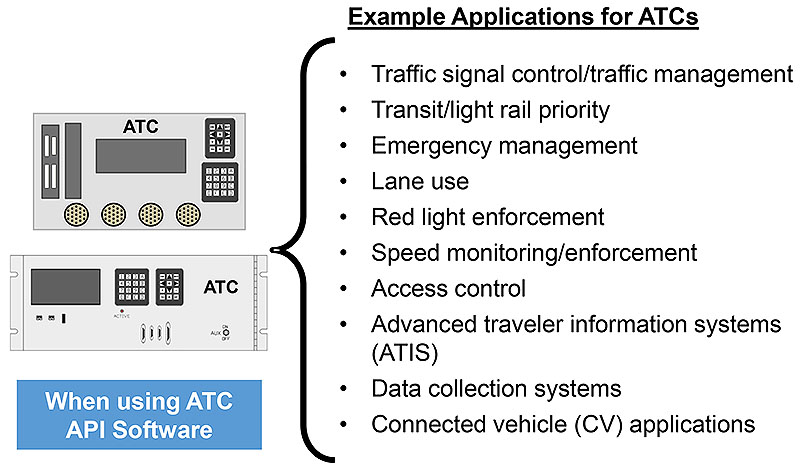
(Extended Text Description: This slide, entitled "Any ATC Can Run Multiple Application Programs Simultaneously," has two graphics of transportation controllers and a text box on the left side of the slide, and a list of 10 applications that could be used in transportation controllers on the right side of the slide. There is a large left brace in the center of the slide indicating that the applications on the right may run within the controllers on the left. The two controllers and the text box are aligned by their centers vertically. The text on the right reads, Example Applications for ATCs, Traffic signal control/traffic management, Transit/light rail priority, Emergency management, Lane use, Red light enforcement, Speed monitoring/enforcement, Access control, Advanced traveler information systems (ATIS), Data collection systems, Connected vehicle (CV) applications. The first controller is twice as wide as it is tall. It has a display centered within the controller, two keypads aligned vertically on the right, and four large circular connectors along the bottom. There are two rectangular expansion slots that are nearly the height of the controller that are next to each other along the left side of the controller. The left most slot has several D-Sub connectors in it. The other slot is empty. It has the word "ATC" at the top center of the controller. The second controller is 2.5 times has wide as it is tall. It is about 10% shorter that the first controller. It has a display on the left side of the controller, two keypads aligned horizontally in the center of the controller, and the word "ATC" at the top right of the controller. Below the display and the keypads there are various connectors. The text box is about the same width as the second controller but approximately 15% shorter. It contains the words "When using ATC API Software." The bulleted text to the right contains the following:
Example Applications for ATCs
- Traffic signal control/traffic management
- Transit/light rail priority
- Emergency management
- Lane use
- Red light enforcement
- Speed monitoring/enforcement
- Access control
- Advanced traveler information systems (ATIS
- Data collection systems
- Connected vehicle (CV) applications
)
Graphics: Ralph W. Boaz
Slide 16
Learning Objective #1
Identify Key Elements of the ATC 5201 Standard v06 Architecture
- Based on an "engine board" concept
- Computational capability can grow with technology
- Uses Linux operating system - open source, multi-process, multi-application
- Mechanical specifications primarily for physical interfaces only
- Works with all major transportation field cabinet system standards and specifications
- Source code portability for application software
- Multiple and concurrent application programs when using application programming interface (API) software
Slide 17:
Learning Objective #1
ATC Engine Board Concept

(Extended Text Description: This slide, entitled "ATC Engine Board Concept," is a graphic representation of a circuit board. It is approximately 40% of the height of the slide twice as wide as it is tall. There are seven variously shaped labeled rectangles representative of electronic components on the board. They are labeled "ENET 1," "ENET 2," "USB," "RTC," "CPU + LINUX O/S," "MEMORY" and "SERIAL I/O." There are two additional rectangles, identical in shape, representative of electronic connectors at the top and bottom of the board.)
Graphics: Ralph W. Boaz
Slide 18:
Learning Objective #1
Engine Boards Used to Create Different Types of Transportation Controllers

(Extended Text Description: This slide, entitled "Engine Boards Used to Create Different Types of Transportation Controllers," is agraphic illustrating how the Engine Board can be used to build controller units that are of different designs. The Engine Board shown in Slide 17 is shown in the lower center of the slide. Its width is about 40% the width of the slide. To the upper left and upper right of the Engine Board are graphics of other electronic boards about equal in size to the Engine Board. They have labels above them "2070 Host Module" and "NEMA Host Module," respectively. The Host Boards are rectangular but angled inward towards the Engine Board. The 2070 Host Module has a slender metallic plate perpendicular to the board on the left side. There is a slender connector running along the right edge of the board. In the center of the board is an Engine Board that takes up approximately 75% the width of the Host Module. The Engine Board is outlined by a heavy dashed line. The NEMA Host Module has a small rectangular connector and four circular connectors running along the bottom of the board. They are all approximately 25% of Host Board in height. There is a slender connector running along the right side of the Host Board but not quite to the edge. There are metallic circles in each of the corners of the board. In the center of the board is an Engine Board that takes up approximately 50% the width of the Host Module. The EngineBoard is outlined by a heavy dashed line. There are four heavy dashed lines connecting the corners of the large Engine Board to the four corners of the Engine Board on the 2070 Host Module. There are four heavy dashed lines connecting the corners of the large Engine Board to the four corners of the Engine Board on the NEMA Host Module.)
Graphics: Ralph W. Boaz
Slide 19:
Learning Objective #1
ATC 5401 Standard Defines API Software Which Allows Concurrent Application Programs
-
Front panel management
- Application programs able to use dedicated window(s
- Operational users interact with window/application program in "focus"
-
Field input/output (I/O) management
- Application programs "register" to access a field I/O device
- Application programs have "read access" to all input and output field devices
- Application programs "reserve" exclusive "write access" to output points of a field I/O device
Slide 20:
Learning Objective #1
ATC 5401 Standard Defines API Software Which
Allows Concurrent Application Programs (cont.)
-
Real-time clock management
- Set/Get Time Functions
- Daylight Saving Time (DST) Functions
- Time Source and Signaling Functions
-
API utilities
- ATC configuration window
- Standard utilities for setting system time, setting Ethernet ports, selecting system services, getting Linux and API information
- Extensible so additional utilities may be added
Slide 21:
Learning Objective #1
Front Panel Manager Window

(Extended Text Description: This slide, entitled "Front Panel Manager Window," is a graphic illustrating how multiple concurrently running programs can operate on a single ATC controller unit. In the upper part of the slide is a square about 1/8 the height of the slide representing a LCD screen and keypads (see Slide #25) portion of a transportation controller. Below the square is an enlargement of the LCD screen. There are dotted lines extending from the LCD in the square to the edges of the enlargement. The enlarged LCD screen is about 25% of the height of the slide and extends almost the entire width of the slide. There are 8 lines x 40 fixed width characters across shown in the LCD as follows: Line 1. "FRONT PANEL MANAGER VER 1.00" Line 2. "SELECT WINDOW: 0-F SET DEFAULT: *,0-F" Line 3. "0 Ramp Meter Prgrm 1*Signal Program" Line 4. "2 Emergency Mngmnt 3 Data Distributor" Line 5. "4 System Checker 5" Line 6. "6 7" Line 7. "8 9" Line 8. "[MORE - UP/DN ARROW] [CONFIG INFO-NEXT]" )
[Application programs shown are for example purposes only and not included in API Software]
Graphics: Ralph W. Boaz
Slide 22:
Learning Objective #1
Examples of ATC Units
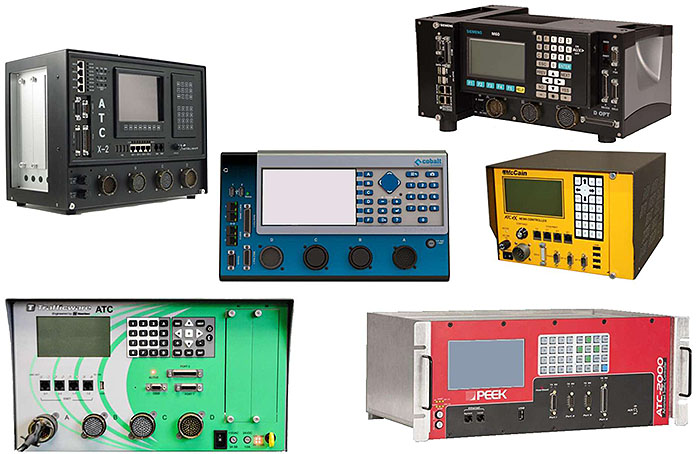
(Extended Text Description: This slide, entitled "Examples of ATC Controller Units," contains six photographs of controllers of various shapes, sizes and designs. All of the controllers have a Liquid Crystal Display (LCD) screen and a key pad with differing arrangements of keys. All of the controllers have various electronic cable connectors including RJ45 jacks typical of Ethernet connections (appear as small dark squares approximately 1/2 " W X 1/2" H), 9 pin Sub D connectors (1" W X 1/2" H) typically used for serial connections, 15 pin Sub D connectors (1.5" W X 1/2" H) typically used for serial connections, 25 pin Sub D connectors (2" W X 1/2" H) typically used for serial connections, and USB ports (1/2" W X 1/4" H) common to computers. Some of the units have round circular connectors about 1.5 inches in diameter. The controllers are arranged in a staggered fashion with two controllers on the left side of the slide, one controller in the middle and three controllers to the right side.
- The controller in the upper left is angled to the right. The unit is 10.75" W X 7.75" D X 10.5" H. On the lower 1/3 of the controller, there are four circular connectors evenly spaced across the width of the controller. They are labeled left to right "A," "B," "C" and "D." To the left of the A connector are two small knobs. Above the circular connectors, on the left 1/8 of the controller are electronic cable connectors rotated 90 degrees so they are shown taller than wider. These include four RJ45 jacks, two 25 pin Sub D connectors, a 9 pin Sub D connector and a 15 pin Sub D connector. There are numerous small LEDs adjacent to the RJ45 jacks. Centered in the upper 1/3 area of the controller is an LCD screen. Below the screen are additional electronic connectors including four USB ports, six RJ45 jacks. To the right of the LCD screen is a keypad with 28 keys. Below the keypad and above the D connector is a knob. Facing the left side of the controller are two panels (1.5" W X 7" H each) which are held in place by two round thumbscrews (each).
- The controller in the lower left is facing forward. The unit is 17.04" W x 11.09" D x 10.03" H. There is an LCD screen on the upper left portion of the controller. It is about 25% of the width and height of the controller. To the right of the LCD screen is a keypad with 30 keys four of which appear to be arrows. Below the LCD screen are four RJ45 jacks and a USB port. Below the key pad are a 9 pin Sub D connector, a 15 pin Sub D connector and a 25 pin Sub D connector. To the right of the keypad are two panels (1.5" W X 7" H each) which are held in place by two round thumbscrews (each). Below the RJ45 jacks and Sub D connectors are four circular connectors evenly spaced across 75% if the width of the controller. They are labeled left to right "A," "B," "C" and "D." To the right of the D connector and below the two panels are a rectangular toggle switch, two plastic screws about .25" in diameter, a group of four LEDs and a plastic key.
- The controller in the center is facing forward. The unit is 14.84" W X 6.13" D X 8.50" H. On the left 1/8 of the controller there are electronic cable connectors rotated 90 degrees so they are shown taller than wider. These include two USB ports, four RJ45 jacks, a 25 pin Sub D connector, a 9 pin Sub D connector and a 15 pin Sub D connector. On the lower 1/3 of the controller and to the right of the electronic cable connectors, there are four circular connectors evenly spaced across the remaining width of the controller. They are labeled left to right "D," "C," "B" and "A." To the right of the A connector is a plastic screw about .25" in diameter. Above the D and C connectors is a LCD screen that takes up about 50% of the height and 40% of the width of the controller. To the right of the screen above the B and A connectors is a keypad with 24 keys. One of the keys is a large diamond shape which appears to have arrows on its corners.
- The controller on the upper right of the slide is angled to the left. The unit is 15.5" W 9.5" D X 7" H. The LCD screen is in the upper center of the controller. Below the LCD are five buttons. To the right of the LCD and buttons is a keypad of 30 keys, four of which are arrows. To the right of the keypad are a 25 pin Sub D connector, a 15 pin Sub D connector, a 9 pin Sub D connector, an RJ45 port and a rectangular infrared port. Below the LCD, Key pad and connectors are three large circular connectors labeled A, B and C. There is a horizontally mounted 37 pin Sub D connector to the right of the C circular connector labeled "D OPT." Arranged on the left side of the controller in thin panel containing with a 9 pin Sub D connector, a 25 pin Sub D connector, a plastic key hole, four USB ports and four RJ45 ports. There are two round thumb screws securing the panel to the controller chassis.
- The controller on the right middle of the slide is angled to the left. The unit is 10" W X 10.5" D X 7" H. There is an LCD screen on the upper left portion of the controller. It is about 30% of the height and 40% of the width of the controller. To the right of the LCD screen is a keypad with 28 keys, four of which appear to be arrows. Below the LCD screen is a knob and four RJ45 jacks. Below the knob is a circular connector. To the left of the circular connector are a knob and a small rectangular toggle switch. Beneath the RJ45 jacks are a 15 pin Sub D connector and three 9 pin Sub D connectors. To the right of the 9 pin Sub D connector and aligned with the right edge of the key pad are four USB ports. To the right of the keypad and USB ports is a panel (1.5" W X 7" H) which is held in place by two round thumbscrews.
- The controller on the lower right is angled to the right. The unit is 19" W x 10.5" D x 7" H. There is an LCD screen on the upper left portion of the controller. It is about 25% of the width and 50% of the height of the controller. To the right of the LCD screen is a keypad with 32 keys. In the lower left front of the controller are two plastic screws about .25" in diameter. To the right of the screws below the left side of the LCD screen are two RJ45 jacks. To the right of the RJ45 jacks aligned with the right side of the LCD screen is a USB port. Below the key pad are a 15 pin Sub D connector, two 9 pin Sub D connectors, and a 25 pin Sub D connector. To the right of the 25 pin Sub D connector is a metal posted toggle switch. On the left and right sides of the controller are wire pull handles that are about 50% of the height of the controller aligned and centered vertically.)
Photos: Econolite, Intelight, McCain, Peek, Siemens, and Trafficware
Slide 23:
Learning Objective #1
Describe How ATC 5201 Standard v06 Works
With Other ITS Standards
- ATC 5201 Standard provides the capability to support multiple applications using different (or same) types of NTCIP communications simultaneously (when using API Software)
- ATC 5201 Standard provides interfaces and computational power for applications such as Adaptive Control and Connected Vehicle applications
- Provides internal cabinet interfaces for Model 33X Cabinets, NEMA TS 1 and TS 2 Type 2 Cabinets, NEMA TS 2 Type 1 Cabinets, and ITS Cabinets
- Generally, ATC 5201 Standard v06 has more rigorous environmental and testing requirements than the major TFCS standards and specifications
Slide 24:
Learning Objective #1
ATC Units in Different TFCSs
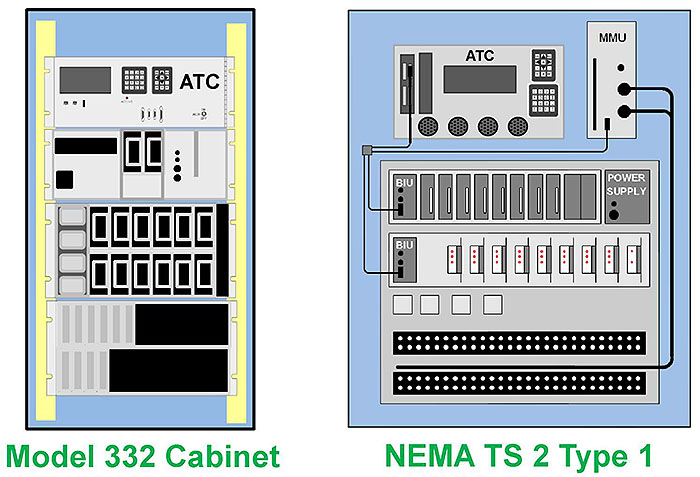
(Extended Text Description: This slide, entitled "ATC Controller Units in Different TFCSs," illustrates that ATC 5201 conforming controller units can be designed to be used in existing TFCSs. The left of the slide is a graphic of the interior Model 332 Cabinet. The graphic is about 65% of the height of the slide and 25% of the width. There are side rails of an equipment rack which run along the left and right sides of the front of the cabinet interior. There are four sections of the equipment that extend edge to edge of the cabinet interior attaching to the side rails of the rack.
- The first (top) section is a controller unit. It is located about 5% of the way down from the top of the rack vertically. LCD, keypads, and various connectors are shown. The controller itself takes up approximately 15% of the vertical rack space. It has the letters "ATC" on the upper right of the controller.
- The second section takes up approximately 15% of vertical rack space and is made up of three areas distributed horizontally across the section. The first area on the left is approximately 40% of the horizontal rack. It contains two rectangles representing components. 50% of the middle area holds two other rectangular components. The third area has lights and/or knobs on its left side and a handle extending down the middle of the subassembly.
- The third section takes up approximately 25% of vertical rack space and is made up of three areas distributed horizontally across the section. The left area takes up approximately 15% of the horizontal width of the assembly. Aligned down the left area are four rounded rectangles. The middle area takes up approximately 75% of the horizontal width of the assembly. It contains two rows of 6 rectangular devices evenly distributed. The right area takes up approximately 5% of the horizontal width of the assembly.
- The fourth section takes up approximately 25% of vertical rack space and is made up of two rows of similar thin rectangular devices. The top row has six of such devices. The bottom row has for of the devices. There is a label "Model 332 Cabinet" centered below the cabinet graphic. The right of the slide is a graphic of the interior of a NEMA TS 2 Type 1 cabinet. The graphic is about 65% of the height of the slide and 40% of the width. There are three sections within the cabinet graphic, two on upper part of the graphic and a larger section below the other two that takes up most remainder of the cabinet.
- The upper left section of the graphic is a controller unit. It is located about 25% of the height and 40% of the width of the graphic. LCD, keypads, four large circular connectors and various other connectors are shown. It has the letters "ATC" at the center top of the controller.
- The upper right section of the graphic (bottom aligned with the controller) is a single device that takes up approximately 30% of height and 10% of the width of the width. It has a thin slot running along the left side of the device, a rectangular connector in lower center of the device, and three round connectors on the right side of the device. It has the letters "MMU" at the center top of the device.
- The lower section of the graphic is a rectangular assembly that takes up approximately 55% of the height and 85% of the width of the graphic cabinet graphic. Within this lower section there are many smaller devices of various shapes and sizes aligned in five rows. – The first row consists of an assembly of devices that take up about 80% of the width of the lower section and 20% of the height. There is an additional device to the right of this assembly that is almost square.
- Starting from the left of the assembly is a rectangular device that is about twice as tall as it is wide. It has three connectors (two round connectors and one rectangular connector) on the left side of the device. It has the letters "BIU" at the top center of the device. To the right of the BIU are eight evenly spaced rectangular devices the same height as the BIU but slightly thinner. Each has a handle. There are two additional devices of the same size as the previous but they are closer together and have no handle.
- The device to the right of the assembly has two circular connectors in the lower left corner. It has the words "POWER SUPPLY" centered at the top
The second row consists of an assembly of devices that take up about the width of the lower section and 20% of the height. Starting from the left of the assembly is a rectangular device that is about twice as tall as it is wide. It has three connectors (two round connector and one rectangular connector) on the left side of the device. It has the letters "BIU" at the top center of the device. To the right of the BIU are eight evenly spaced nine rectangular devices. These devices consist of a smaller rectangle with three lights (except for the far right one has two lights) attached to a thick line that extends to the same height of the BIU. – The third row consists of four squares about 5% of the lower section height. The four squares are evenly spaced and take up the left half of the row. – The fourth row has a single long rectangular rack of 54 round connectors arranged in in 2 rows and evenly spaced. – The fifth row is the same as the fourth.
- There is a thin cable extending from a rectangular connector on the controller downward then to a small square near the left side of the graphic just above the lower section. There is a thin cable extending downward from the MMU then leftward to the small square. A thin cable extends downward from the small square then to the right to connect to a rectangular connector on the BIU in row one of the lower section. There is another thin cable that extends downward from the small square then to the right to connect a rectangular connector on the BIU in row two of the lower section. There are two thick cables which extend from round connectors on the MMU to the right and then downward along the right outside of the lower section then to the left across the lower section in between rows 4 and 5. There is a label "NEMA TS 2 Type 1" centered below the cabinet graphic.
)
Graphics: Ralph W. Boaz
Slide 25:
Learning Objective #1
ATC 5201 Working With Other ITS Standards
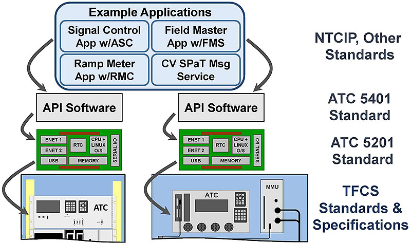
(Extended Text Description: This slide, entitled "ATC 5201 Working With Other ITS Standards," illustrates how ATC 5201 and ATC 5401 Standard enables the use of other ITS standards. There is a graphic on the left 2/3 of the slide. On the right 1/3 of the slide are labels that identify the standards that are used at each level. Level 1 of the graphic shows the top portions of the graphic illustrations of the Caltrans 332 and the NEMA TS 2 cabinets from the previous slide aligned side by side. In the Caltrans 332 cabinet, the ATC controller is shown. In the NEMA TS 2 Type 1 Cabinet the ATC controller and the MMU are shown. To the right of the cabinets is the label "TFCS Standards & Specifications." Level 2 of the graphic shows two Engine Board graphics as described in Slide 55 except they are about 1/8 the width and 1/10 the height of the slide. They are aligned side by side and centered above the cabinet graphics (one over each cabinet). There are thick curved arrows extending out of the left side of each Engine Board and pointing to the left side of the controller in the cabinets below them. To the right of the cabinets is the label "ATC 5201 Standard." Level 3 of the graphic shows a rectangle labeled "API Software" above each of the two Engine Boards. They are aligned side by side and centered above the Engine Board graphics (one over each Engine Board). There are thick curved arrows extending out of the left side of the API Software Pillar Consulting, Inc.rectangles and pointing to the left side of the Engine Boards below them. To the right of the API Software rectangles is the label "ATC 5401 Standard." Level 4 is a large rounded rectangle that is about 25% of the height of the slide and 40% of the width of the slide. It is aligned so that it is centered above the two API Software rectangles. At the top of the rounded rectangle is the label "Example Applications." The remainder of the large rounded rectangle is made up of four identically sized rounded rectangles. The upper left rounded rectangle is labeled "Single Control App w/ASC." The upper right rounded rectangle is labeled "Field Master App w/FMS." The lower left rounded rectangle is labeled "Ramp Meter App w/RMC." The lower right rounded rectangle is labeled "SPAT Message Service." There is a thick curved arrow extending out of the left side of the large rounded rectangle and pointing to the left side of the API Software rectangle to the lower left. There is a thick curved arrow extending out of the right side of the large rounded rectangle and pointing to the right side of the API Software rectangle to the lower right. To the right of the large rounded rectangle is the label "NTCIP, Other Standards.")
Graphics: Ralph W. Boaz
Slide 26:

Slide 27:
Learning Objective #1
Which of the following features of ATC units allows them to run concurrent application programs?
Answer Choices
- Has a computational capability that can grow with technology
- Works with all major transportation field cabinet systems
- Works with NTCIP standards
- Runs API software
Slide 28:
Learning Objective #1
Review of Answers
 a) Has a computational capability that can grow with technology
Incorrect. Being able to grow with technology is a feature of ATCs which mitigates obsolescence.
 b) Works with all major transportation field cabinet systems
Incorrect. This feature allows ATC units with contemporary processing power to be used to upgrade older cabinet systems.
 c) Works with NTCIP standards
Incorrect. ATC units provide the computing resources for NTCIP communications but the applications determine their use.
 d) Runs API software
Correct! The API software, defined by the ATC 5401 Standard, runs on ATC units and allows application programs to share the resources of the controller.
Slide 29:
Summary of Learning Objective #1
Identify the Advantages of Transportation Controllers Based on ATC 5201 Standard v06
- Discuss the purpose of the ATC 5201 Standard v06
- Identify key elements of the ATC 5201 Standard v06 architecture
- Describe how ATC 5201 Standard v06 works with other ITS standards
Slide 30:
Learning Objective #2: Describe a Systems Engineering-Based ATC Specification Development Process
- Traditional approaches to developing transportation controller procurement specifications
- Systems engineering approach to developing an ATC procurement specification
- Benefits of the specification development process
- Challenges to preparing a good ATC specification
Slide 31:
Learning Objective #2
Traditional Approaches to Developing Transportation Controller Procurement Specification
-
Not based on formalized user needs and requirements)
- Agencies often use an existing specification, copy it, and distribute
- Not connected to other stakeholders who may have user needs that apply to the transportation controller
- Funding problems as policy makers and senior managers see no relationship between their approved strategic or regional plans and the potential solutions offered by ATCs
- Hardware and application procurement are combined for a single purpose use (e.g. signal control, ramp meter, data collection)
Slide 32:
Learning Objective #2
Systems Engineering Approach to Developing an ATC Procurement Specification
- Develop concept of operations with user needs
- Develop requirements based on user needs
- Show traceability to user needs in an ATC specification
Slide 33:
Learning Objective #2
Systems Engineering Processes Used in Standards Development
IEEE - Systems Engineering
An interdisciplinary collaborative approach to derive, evolve, and verify a life cycle balanced system solution that satisfies customer expectations and meets public acceptability.
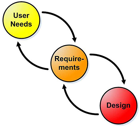
(Extended Text Description: This slide, entitled "Systems Engineering Processes Used in Standards Development," uses a graphic that illustrates the systems engineering process used in standards development. This graphic introduces three circles evenly spaced in a descending fashion from left to right. They contain the text "User Needs," "Requirements" and "Design," respectively. There is a curved arrow leading from the "User Needs" circle to the "Requirements" circle. There is a curved arrow leading from the "Requirements" circle to the "User Needs" circle. This same arrange of arrows occurs between the "Requirements" circle and the "Design" circle.)
Graphics: Ralph W. Boaz
Slide 34:
Learning Objective #2
Systems Engineering Specification Development Process

(Extended Text Description: This slide, entitled "Systems Engineering Specification Development Process," uses a graphic that illustrates the systems engineering process used to develop a specification. There are two circles evenly spaced in a descending fashion from left to right representing processes. They contain the text "User Needs" and "Requirements," respectively. There is a curved arrow extending from the User Needs process to the Requirements process. There is a curved arrow extending from the Requirements process to the User Needs process. There are three rectangular graphics with lines across them representing documents. The first document is located at the top of the slide and is labeled "Strategic or Regional Plans." It has a curved arrow extending from the document to the User Needs process. There is a curved arrow extending from the User Needs process two the second document located in the lower left of the slide that is labeled "Concept of Operations." There is a curved arrow extending from the Requirements process to the third document located in the lower right of the slide that is labeled "Agency Specification." There is a dotted double arrow extending between the second and third documents. The double arrow is labeled "Traceability.)
Graphics: Ralph W. Boaz
Slide 35:
Learning Objective #2
Relationships of User Needs and Requirements
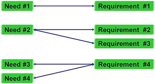
(Extended Text Description: This slide, entitled "Relationships of User Needs and Requirements," uses graphics to highlight the relationships between a user needs and requirements. User needs are represented by green boxes on the left side of the slide labeled "Need #1," "Need #2," "Need #3," and "Need #4." Requirements are represented by green boxes on the right side of the slide labeled "Requirement #1," "Requirement #2," "Requirement #3," and "Requirement #4." Three relationships between the user needs and the requirements are represented using solid blue lines with arrows on each end connecting the needs and requirements as follows: One-to-One – Need #1 is connected to Requirement #1; One-to-Many – Need #2 is connected to Requirement #2 and Requirement #3; and Many-to-One – Need #3 and Need #4 are connected to Requirement #4.)
Graphics: Ralph W. Boaz
Slide 36:
Learning Objective #2
Benefits of the Systems Engineering Specification Development Process
- User needs identified by a broad base of stakeholders
- Existing strategic or regional plans already approved by policy makers and higher management are part of user needs development
- Provides justification for investment in ATC units that non-technical people can understand
- Shows accountability to the public
Slide 37:
Learning Objective #2
Challenges to Preparing a Good ATC Specification
- Internal resistance to change
- External resistance to change
- Procurement schedules may not allow for the time and effort to go through a rigorous process
- Identifying and getting stakeholders together
- Difficulty getting stakeholders to describe their user needs as opposed to design requirements
- Often, people procuring the equipment are unfamiliar with a systems engineering process
Slide 38:

Slide 39:
Learning Objective #2
Which of the following is NOT a good source for discovering user needs?
Answer Choices
- Regional plans
- Integration testing
- Stakeholders
- Strategic plans
Slide 40:
Learning Objective #2
Review of Answers
 a) Regional plans
Incorrect. Regional plans provide insight into the future and are a good source for discovering user needs.
 b) Integration testing
Correct! It is not a good practice to depend on integration testing to discover user needs.
 c) Stakeholders
Incorrect. Stakeholders are a good source (essential source) for discovering user needs.
 d) Strategic plans
Incorrect. Strategic plans provide insight into the future and are a good source for discovering user needs.
Slide 41:
Summary of Learning Objective #2
Describe a Systems Engineering-Based ATC Specification Development Process
- Traditional approaches to developing transportation controller procurement specifications
- Systems engineering approach to developing an ATC procurement specification
- Benefits of the specification development process
- Challenges to preparing a good ATC specification
Slide 42:
Learning Objective #3: Identify and Write User Needs for ATCs
- Sources of needs for ATCs
- Characteristics of well-written user needs
- User needs as a process of discovery
Slide 43:
Learning Objective #3
Sources of User Needs for ATCs
- Stakeholders
-
Derived user needs from:)
- Existing strategic or regional plans
- Existing or planned operational applications
-
Architectural constraints (similar to user needs))
- Existing or planned transportation field cabinet systems
- Existing or planned communications infrastructure
- Derived user needs from ATC 5201 Standard v06
Slide 44:
Learning Objective #3
Sources of User Needs - Stakeholders
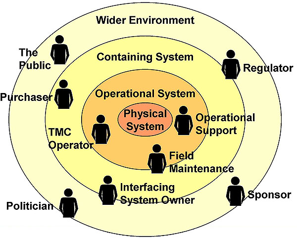
(Extended Text Description: This slide, entitled "Sources of User Needs – Stakeholders" illustrates the broad base of stakeholders that could contribute user needs for an ATC project. It uses a graphic of four concentric circles arranged in a fashion similar to an archery target. The innermost circle is a reddish tan. The three bands of colors that are further from the center are in lighter shades of tan. This is called an "onion diagram" as onions are made up of multiple layers. The inner circle is labeled "Physical System." The next layer outward is labeled "Operational System." The next layer outward is labeled "Containing System." The outermost layer is labeled "Wider Environment." There are smaller black representations of people positioned in the different layers of the diagram. Each person has a project role next to it as follows: Inner Circle has no people – It represents the system; Next Layer Outward has three people labeled "TMC Operator", "Field Maintenance" and "Operational Support" respectively; Next Layer Outward has two people labeled "Interfacing System Owner" and "Purchaser" respectively; and Outermost Layer has four people labeled "Sponsor," "Regulator," "The Public" and "Politician" respectively. The picture demonstrates while they are all stakeholders, different stakeholders have different levels of influence on the physical system to be defined. The most influence coming from those closest to the center.)
© Ian Alexander 2006 (adapted with permission)
Slide 45:
Learning Objective #3
Characteristics of Well-Written User Needs
- Uniquely identifiable
- Major desired capability
- Captures rationale
- Solution-free
Slide 46:
Learning Objective #3
An Example User Need
7.8.2.1 Traffic Signal Control
The user needs to safely control the flow of traffic through the city's signalized intersections. There are over 100 signalized intersections within the city limits. The city uses pre-timed, semi-actuated and fully actuated modes of traffic signal operation. Traffic signals may be operated as a standalone intersection or in coordination with other intersections.
| Uniquely Identifiable? | ✓ |
| Major Desired Capability? | ✓ |
| Captures Rationale? | ✓ |
| Solution-Free? | ✓ |
Slide 47:
Learning Objective #3
An Example User Need
7.3.5 Keypads
The user needs the controller to have keypads as described in Section 9.4.2 of the Caltrans TEES 2009. The city has had no maintenance issues with these types of keypads on their existing controllers. The keypads work well with the city's existing signal control software.
| Uniquely Identifiable? | ✓ |
| Major Desired Capability? | X |
| Captures Rationale? | X |
| Solution-Free? | X |
Slide 48:
Learning Objective #3
User Needs as a Process of Discovery
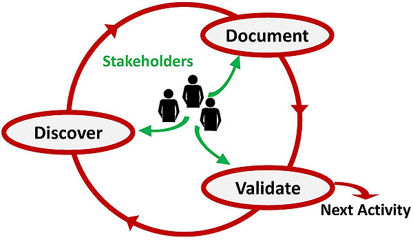
(Extended Text Description: This slide, entitled "User Needs as a Process of Discovery," shows how the development of user needs can be a process of discovery. It shows a large circle with three arrows located equidistantly around the circle pointing in a clock-wise direction. Between the arrows are three ovals with text located equidistantly around the circle. The first oval (on the left side of the circle) says "Discover." Going clockwise around the circle, the next oval says "Document." Continuing clock-wise around the circle the next oval says "Validate." In the middle of the circle are small representations of people with the word "Stakeholders" over them. There are arrows pointing out from the people to the ovals around the circle. The "Validate" oval (located on the lower right portion of the circle has an arrow pointing from the oval to text to the right that says "Next Activity.")
© Ian Alexander 2006 (adapted with permission)
Slide 49:
Learning Objective #3
User Needs from Strategic and Regional Plans
Case Study
This section uses examples from the "Orange County Intelligent Transportation Systems (ITS) Strategic Deployment Plan (SDP) - Update 2013." This SDP was developed by the Orange County Transportation Authority (OCTA), a Metropolitan Planning Organization (MPO) for Orange County, CA.
The SDP uses ITS "strategies" to provide context for the agencies and the private sector who are deploying technology today and for the following ten years. Strategies are organized as follows: Transit management and multi-modal (MM); traffic management (TM), incident management and emergency response (IM), traveler information (TI), performance monitoring (PM), communications and connectivity (CC), safety (SF), and institutional (IN).
Other strategic or regional plans may have different names and different methods of expressing desired capabilities.
Slide 50:
Learning Objective #3
Example "Strategies" from Orange County ITS Strategic Deployment Plan
MM2 - Bus Rapid Transit (BRT): Roll out BRT service in a two-step implementation process. Technology applications could include transit signal priority (TSP), real-time bus arrival information, and automated fare collection.
MM5 - Support for Pedestrian and Bicycle Travel: Local deployments of pedestrian and bicycle safety, bike-sharing, and information technologies.
Slide 51:
Learning Objective #3
Example User Needs Derived from Orange County ITS SDP "Strategies"
7.8.3.3 Increase Public Use of Transit Buses
The city needs transportation controllers that can be used to help increase ridership of transit buses. The city needs to improve customer service and ridership experience through the use of field applications that may include TSP (transit signal priority), real-time bus arrival information, automated fare collection, and others.
7.8.6.1 Non-Vehicle Modes of Transportation
The city needs transportation controllers that provide for pedestrian and bicycle applications. This is to reduce vehicle congestion, improve safety, and promote non-motorized travel.
Slide 52:
Learning Objective #3
Example "Strategies" from Orange County ITS Strategic Deployment Plan
CC1 - Countywide Communications Master Plan: Physical and logical connectivity to support multi-modal and multi-agency operations and data sharing needs.
CC3 - Provide a Connected Vehicles Platform: Allow for the future possibility of connected vehicles in order to capitalize on the robust local operational environment and further enhance the existing foundation.
Slide 53:
Learning Objective #3
Example User Needs Derived from Orange County ITS SDP "Strategies"
7.4.3.1 Multi-Network Ready
The city needs transportation controllers equipped with communications capabilities to accommodate connectivity with multiple systems and communications networks. The city has legacy center-to-field (C2F) communications to some arterials. The majority of the arterials are supported by Ethernet communications through fiber or high speed radios. It is expected that some applications will share a physical network while others will require separate networks.
Slide 54:
Learning Objective #3
Example User Needs Derived from Orange County ITS SDP "Strategies" (cont.)
7.5.1 Connected Vehicle V2I Communications
The city needs transportation controllers that have the processing power to perform connected vehicle vehicle-to-infrastructure (V2I) communications. Connected vehicle applications have the potential for a major advancement in integrated traveler information, safety, transportation management, and eco driving.
Slide 55:
Learning Objective #3
Example Architectural Constraint
6.5.1 Transportation Field Cabinet Systems
The city needs transportation controllers equipped for existing transportation field cabinet systems. The city has 70% of its TFCSs that are NEMA TS 2 Type 1 and 30% of its TFCSs are NEMA TS 2 Type 2. The transportation controllers should be suitable for these cabinet systems.
Slide 56:
Learning Objective #3
Deriving User Needs From ATC 5201 Standard v06
- ATC 5201 v06 did not go through a formal systems engineering process
- ATC 5201 v06 contains a section called "representative usage" where user needs are expressed as "features"
-
Features are organized into three major categories)
- Manage/configure applications
- Manage external devices
- Facilitate ease of maintenance and future hardware/software updates
Slide 57:
Learning Objective #3
Features From ATC 5201 Standard v06
2.3.1 Manage/Configure Applications
2.3.1.1 Install/Update Applications Software Quickly and Efficiently
2.3.1.2 Install/Upgrade O/S Quickly and Efficiently
2.3.1.3 Manage Clock/Calendar Function and Synchronize with Reliable External Source
2.3.1.4 Configure and Verify Parameters for Particular Local Applications
2.3.1.5 Upload/Download Data Block(s) as needed to Transfer Files and Accommodate Bulk Transfers of new Application Databases
Slide 58:
Learning Objective #3
Features From ATC 5201 Standard v06
2.3.1 Manage/Configure Applications (cont.)
2.3.1.6 Monitor and Verify Present Applications Status
2.3.1.7 Allow Operator Control of Application Execution
2.3.1.8 Facilitate the Long Term Storage of Data for Logging and other Data Storage Applications
Slide 59:
Learning Objective #3
Features From ATC 5201 Standard v06
2.3.2 Manage External Devices
2.3.2.1 Manage/Control a Variety of External Field Devices
2.3.2.2 Monitor the Output and Status of a Variety of External Field Devices
2.3.3 Facilitate Ease of Maintenance and Future Hardware/Software Updates
2.3.3.1 Maintain/Update Controller Hardware
2.3.3.2 Maintain/Update Controller Software
2.3.3.3 Support Diagnostics
Slide 60:
Learning Objective #3
Converting ATC Standard v06 Features Into User Needs
Feature
2.3.1.1 Install/Update Applications Software Quickly and Efficiently
This feature allows the local operator or a remote computer to install or update the application software resident on the ATC.
User Need
7.3.8 Install/Update Applications Software Quickly and Efficiently
The user needs to be able to install or update the application software resident on the controller unit. Users may or may not use application programs from the original manufacturer. All application programs need maintenance over time. Depending on the user's organization, application updates may be performed directly on the controller unit, from computer connection, or remotely through a network.
Slide 61:
Learning Objective #3
Converting ATC Standard v06 Features Into User Needs
User Need
7.3.8 Install/Update Applications Software Quickly and Efficiently
The user needs to have the ability to install or update the application software resident on the ATC unit. Users may or may not use application programs from the original manufacturer. All application programs need maintenance over time. Depending on the user's organization they may desire the option to perform these actions directly on the ATC unit or remotely through a computer or computer network.
| Uniquely Identifiable? | ✓ |
| Major Desired Capability? | ✓ |
| Captures Rationale? | ✓ |
| Solution Free? | ✓ |
Slide 62:
Learning Objective #3
Converting ATC Standard v06 Features Into User Needs
Feature
2.3.3.1 Maintain/Update Controller Hardware
This feature addresses the need for controller unit hardware to be maintained and updated as technology changes and additional functional and performance capabilities are needed.
User Need
7.7.2 Maintain/Update Controller Hardware
The user needs the controller unit to be upgradeable. Controller units are commonly in the field for seven years or more. This leads to obsolescence. The user needs to be able to upgrade the controller unit as technology changes and additional functional and performance capabilities are needed.
Slide 63:
Learning Objective #3
Converting ATC Standard v06 Features Into User Needs
User Need
7.7.2 Maintain/Update Controller Hardware
The user needs the controller unit to be upgradeable. Controller units are commonly in the field for seven years or more. This leads to obsolescence. The user needs to be able to upgrade the controller unit as technology changes and additional functional and performance capabilities are needed.
| Uniquely Identifiable? | ✓ |
| Major Desired Capability? | ✓ |
| Captures Rationale? | ✓ |
| Solution Free? | ✓ |
Slide 64:

Slide 65:
Learning Objective #3
Which of the following is NOT a source of user needs for the specification development process?
Answer Choices
- Brand of controller equipment currently used by the agency
- Existing type of transportation field cabinet systems
- Existing strategic or regional plans
- Stakeholders
Slide 66:
Learning Objective #3
Review of Answers
 a) Brand of controller equipment currently used by the agency
Correct! The fact that an agency is using a particular brand of equipment should not become a user need. With ATCs software applications will be portable across vendors.
 b) Existing type of transportation field cabinet systems
Incorrect. The types of TFCSs being or planned to be used by the agency becomes a constraint user need for the controller equipment.
 c) Existing strategic or regional plans
Incorrect. These higher level types of documents help provide the "vision" for the agency and are a source from which user needs can be derived.
 d) Stakeholders
Incorrect. Stakeholders are the primary source of user needs for the transportation controller equipment (especially operational stakeholders).
Slide 67:
Summary of Learning Objective #3
Identify and Write User Needs for ATCs
- Sources of needs for ATCs
- Characteristics of well-written user needs
- User needs as a process of discovery
Slide 68:
Learning Objective #4: Develop a Concept of Operations (ConOps)
- Structure of a ConOps
- Organizing user needs
- Traceability of user needs to sources
Slide 69:
Learning Objective #4
Structure of a ConOps
-
Example from the FHWA Systems Engineering Guidebook V3 -Modified
- Purpose of document
- Scope of the project
- Referenced documents
- Background
- Concept for the proposed procurement
- User-oriented operational description
- User needs
- Appendices
Slide 70:
Learning Objective #4
Content of the ConOps
-
Purpose of document
- Brief statement 1 -2 paragraphs
- Expected operations of the system to be procured
- Instrument for stakeholder discussion and consensus
- Briefly describe contents, intention, and audience
Slide 71:
Learning Objective #4
Content of the ConOps (cont.)
-
Scope of the project)
- Brief statement 1 -2 paragraphs
- Brief overview of the system to be procured
- The departments involved and other agencies involved directly or indirectly
-
Referenced documents)
- List supporting documentation used and other resources that are useful in understanding the operation of the system
- List documentation of any operational documents, strategic, or regional plans that drive the goal of the procurement
Slide 72:
Learning Objective #4
Content of the ConOps (cont.)
-
Background)
- Brief description of the current equipment, how it is used currently, and its drawbacks
- Reasons for the proposed procurement and the general approach to improvements
-
Concept for the proposed procurement)
- Discuss alternative concepts and why they are not optimal
- High-level description of an ATC
- Justification for the approach
Slide 73:
Learning Objective #4
Content of the ConOps (cont.)
-
User-oriented operational description
- Section focuses on how the goals and objectives are accomplished currently
- Describes strategies, tactics, policies, and constraints
- Describes stakeholders including the users and what the users do
- Describes personnel capabilities, organizational structures, personnel & inter-agency interactions, and types of activities
Slide 74:
Learning Objective #4
Content of the ConOps (cont.)
-
User Needs)
- Here is a description of the vision, goals & objectives, and personnel needs that drive the requirements for the system
- User needs are well-written as discussed in Learning Objective #3
- It is recommended that user needs are organized in a fashion similar to the that of the requirements in the specification
-
Appendices)
- Traceability matrix
- Glossary
- Backup or background material for the sections
- Notes
Slide 75:
Learning Objective #4
Organizing User Needs
- Quality and construction user needs
- TFCS user needs
- User interface user needs
- Communications user needs
- Application user needs
- Environmental and testing user needs
- Warranty user needs
- Other user needs
Slide 76:
Learning Objective #4
Traceability of User Needs to Sources
- Include a table in the ConOps that maps each user need to source documents if they exist
| UN ID | User Need | Source(s) |
|---|---|---|
| 7.7.2 | Maintain/Update Controller Hardware | ATC5201(Sec4) |
| 7.8.2.1 | Traffic Signal Control | Stakeholders |
| 7.8.3.3 | Increase Public Use of Transit Buses | SDP(MM2) |
| 7.8.6.1 | Non-Vehicle Modes of Transportation | SDP(MM5) |
Slide 77:

Slide 78:
Learning Objective #4
Which of the following is a TRUE statement?
Answer Choices
- There is only one way to organize user needs in a ConOps
- A ConOps for an ATC is written from a vendor's point of view
- Consider your specification when organizing your user needs
- A ConOps is just "busy work"
Slide 79:
Learning Objective #4
Review of Answers
 a) There is only one way to organize user needs in a ConOps
Incorrect. There are various ways to organize user needs in a ConOps. The method used in this module is a suggestion.
 b) A ConOps for an ATC is written from a vendor's point of view
Incorrect. A ConOps should be written from the user's point of view.
 c) Consider your specification when organizing your user needs
Correct! Organizing the user needs in a ConOps, in a similar fashion to the way you will organize requirements in your specification, facilitates traceability and understanding.
 d) A ConOps is just "busy work"
Incorrect. A ConOps focuses users to think of what they need and express it in terms they understand.
Slide 80:
Summary of Learning Objective #4
Develop a Concept of Operations (ConOps)
- Structure of a ConOps
- Organizing user needs
- Traceability of user needs to sources
Slide 81:
What We Have Learned
- ATC 5201 Standard v06 and the ATC 5401 application programming interface_ work together so that ATC units can run multiple application programs simultaneously.
- A systems engineering specification development process provides traceability from user needs in a ConOps to requirements in the Agency Specification.
- Well-written user needs are uniquely identifiable, a major desired capability, captures the rationale, and are solution free .
- Showing the sources of user needs in the ConOps can demonstrate the connection of the user needs to the agency's regional and strategic plans.
Slide 82:
Resources
- United States Department of Transportation. Systems Engineering Guidebook for Intelligent Transportation Systems Version 3.0. USDOT, November 2009. https://www.fhwa.dot.gov/cadiv/segb/
- Caltrans Transportation Electrical Equipment Specifications (TEES), 12 March 2009
- NEMA Standards Publication TS 2-2003 v02.06 Traffic Controller Assemblies with NTCIP Requirements
- Institute of Transportation Engineers http://www.ite.org/standards/
- ITS PCB Training Home
- Orange County Strategic Deployment Plan 2013 Update http://www.scag.ca.gov/Documents/OrangeCounty Aug2013Update Final.pdf
Slide 83:
Next Course Module
A307b: Understanding Requirements for Advanced Transportation Controllers Based on ATC 5201
Standard v06
Concepts taught in Module (Learning Objectives):
- Describe a systems engineering based ATC specification development process
- Write requirements for ATCs based on user needs
- Describe a specification based on ATC 5201 Standard v06
- Verify an ATC procurement specification
Slide 84:
