Module 46 - T203 Part 2 of 2
T203 Part 2 of 2: How to Develop Test Cases for an ITS Standards-Based Test Plan, Part 2 of 2
HTML of the PowerPoint Presentation
(Note: This document has been converted from a PowerPoint presentation to 508-compliant HTML. The formatting has been adjusted for 508 compliance, but all the original text content is included, plus additional text descriptions for the images, photos and/or diagrams have been provided below.)
Slide 1:

(Extended Text Description: Welcome - Graphic image of introductory slide. A large dark blue rectangle with a wide, light grid pattern at the top half and bands of dark and lighter blue bands below. There is a white square ITS logo box with words "Standards ITS Training" in green and blue on the middle left side. The word "Welcome" in white is to the right of the logo. Under the logo box is the logo for the U.S. Department of Transpotation, Office of the Assistant Secretary for Research and Technology.)
Slide 2:

(Extended Text Description: This slide, entitled "Welcome" has a photo of Ken Leonard, Director, ITS Joint Program Office, on the left hand side, with his email address, Ken.Leonard@dot.gov. A screen capture snapshot of the home webpage is found on the right hand side - for illustration only - from August 2014. Below this image is a link to the current website: www.its.dot.gov/pcb - this screen capture snapshot shows an example from the Office of the Assistant Secretary for Research and Development - Intelligent Transportation Systems Joint Program Office - ITS Professional Capacity Building Program/Advanced ITS Education. Below the main site banner, it shows the main navigation menu with the following items: About, ITS Training, Knowledge Exchange, Technology Transfer, ITS in Academics, and Media Library. Below the main navigation menu, the page shows various content of the website, including a graphic image of professionals seated in a room during a training program. A text overlay has the text Welcome to ITS Professional Capacity Building. Additional content on the page includes a box entitled What's New and a section labeled Free Training. Again, this image serves for illustration only. The current website link is: https://www.its.dot.gov/pcb.)
Slide 3:

Slide 4:
T203 Part 2 of 2: How to Develop Test Cases for an ITS Standards-Based Test Plan, Part 2 of 2
Slide 5:
Instructor

Manny Insignares
Vice President, Technology Consensus Systems Technologies
New York, NY, USA
Slide 6:
Target Audience
- Traffic management and engineering staff
- Maintenance staff
- System developers
- Test personnel
- Private and public sector users including manufacturers
Slide 7:
Recommended Prerequisite(s)
- T101: Introduction to ITS Standards Testing
- T201: How to Write a Test Plan
- T202: Overview of Test Design Specifications, Test Case Specifications, and Test Procedures
- T203 Part 1 of 2: How to Develop Test Cases for an ITS Standards-Based Test Plan, Part 1 of 2
Slide 8:
Curriculum Path
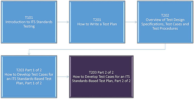
(Extended Text Description: Curriculum Path: A graphical illustration indicating the sequence of training modules that lead up to and follow each course. Each module is represented by a box with the name of the module in it and an arrow showing the logical flow of the modules and the current module highlighted. This slide focuses on the modules that lead up to the current course. The first box is labeled "T101 Introduction to ITS Standards Testing" followed by a line that connects to a box labeled "T201 How to Write a Test Plan" followed by a line that connects to a box labeled "T202 Overview of Test Design Specifications, Test Cases and Test Procedures." The T202 Module is connected to a box labeled "T203 Part 1 of 2: How to Develop Test Cases for an ITS Standards-based Test Plan, Part 1 of 2." This box, in turn connects to a box, colored to indicate that it represents this module, labeled "T203 Part 2 of 2: How to Develop Test Cases for an ITS Standards-based Test Plan, Part 2 of 2.")
Slide 9:
Learning Objectives
Part 1 of 2:
- Review the role of test cases within the overall testing process.
- Discuss ITS data structures used in NTCIP and center-to-center standards (TMDD), and provide examples.
- Learn to find information needed to develop a test case.
- Understand test case development.
Part 2 of 2:
- Handle standards that are with and without test documentation.
- Develop a Requirements to Test Case Traceability Matrix (RTCTM).
- Identify types of testing.
- Recognize the purpose of the test log and test anomaly report.
Slide 10:
Brief Review of Part 1 Discussion
- We have discussed the role of test cases within the overall testing process and test plan.
- We have discussed ITS data structures used in NTCIP and center-to-center standards (TMDD).
- We have learned about the test case development process.
- We have learned where to find information needed for test case preparation.
Let's re-cap IEEE 829 and the relationship between test cases and test procedures, then continue with the remaining four learning objectives 5-8.
Slide 11:
What does IEEE Std 829 Provide?
-
Guidance and formats for preparing testing documentation:
- Test Plan
- Test Design Specification
- Test Case Specification
- Test Procedure Specification
-
Test Reports
- Test Log
- Test Anomaly Report
- Test Report
- Testing professionals across ITS are familiar with these definitions' formats
Slide 12:
Testing Documentation Structure (IEEE Std 829)
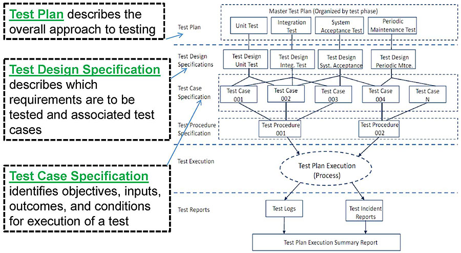
(Extended Text Description: Author's relevant notes: This slide shows a diagram with test documentation in a layered diagram. The layers from top to bottom are labeled: Test Plan, Test Design Specification, Test Case Specification, Test Procedure Specification, Test Execution, Test Reports. Lines connect to show a one-for-one relationship of test design specifications to test plans, multiple test cases to a test design, multiple test cases to a test procedure. A single test is executed based on the test documentation resulting in test log, test anomaly, and test reports. The slide shows the definitions of Test Plan - describes the overall approach to testing, Test Design Specification - describes which requirements are to be tested and associated test cases, and Test Case Specification - identifies objectives, inputs, outcomes, and conditions for execution of a test. The diagram to the right has the following content: Test documentation is shown in a layered diagram. Three boxes made of dashed lines run from top to bottom along the left side. The first box contains the text – Test Plan describes the overall approach to testing. The second box contains the text – Test Design Specification describes which requirements are to be tested and associated test cases. The third box contains the text – Text Case Specification identifies objectives and inputs, outcomes, and conditions for execution of a test. Each box points to its corresponding place on the diagram to the right. The layers from top to bottom are labeled: Test Plan, Test Design Specification, Test Case Specification, Test Procedure Specification, Test Execution, Test Reports. The Test Plan layer contains a large dashed rectangle surrounding four other rectangles. Each rectangle is labeled differently. They are, from left to right, Unit Test, Integration Test, System Acceptance Test, and Periodic Maintenance Test. The Test Design Specification Layer contains four boxes, each connecting to a corresponding box on the previous layer. They are labeled, from left to right, Test Design Unit Test, Test Design Integ. Test, Test Design Sys. Acceptance, and Test Design Periodic Mtce. The Test Case Specification layer contains five boxes that are labelled Test Case 001, Test Case 002, Test Case 003, Test Case 004, and Test Case N. Each Test Case is connected to multiple boxes in the previous layer. Test Case 001 is connected to Test Design Unit Test and Test Design Integ. Test. Test Case 002 is connected to Test Design Unit Test, Test Design Integ Test, and Test Design Sys. Acceptance. Test Case 003 is connected to Test Design Integ Test and Test Design Sys. Acceptance. Test Case 004 is connected to Test Design Sys. Acceptance and Test Design Periodic Mtce. Test Case N is connected to Test Design Periodic Mtce. The Test Procedure Specification layer contains two rectangles containing the text Test Procedure 001 and Test Procedure 002. Test Procedure 001 links back to Test Cases 001 – 003. Test procedure 002 links back to Test Case 004 and N. The Text Execution layer has a single dashed oval labeled Test Plan Execution (Process) and Is linked back to both Test Procedures. The final layer is Test Reports and contains three text boxes. The top two are labeled Test Logs and Test Incident Reports and they connect back to Test Plan Execution. These boxes also lead down to the final box via arrows and this final box is labeled Test Plan Execution Summary Report.)
Slide 13:
Testing Documentation Structure (cont.)
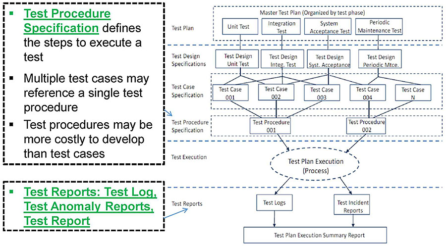
(Extended Text Description: Author's relevant notes: This slide shows the same diagram as in the previous slide. The slide shows definitions of Test Procedure Specification - defines the steps to execute a test, Multiple test cases may reference a single test procedure, Test procedures may be more costly to develop than test cases, and Test Reports: Test Log, Test Anomoly Reports, Test Report.)
Slide 14:
Learning Objective #5
Learning Objective #5: Handle Standards That Are With and Without Test Documentation
- Learn how to develop test cases where test documentation is not included in the standard: Case Study-1: NTCIP 1205 CCTV
- Learn how to develop test cases where test documentation is included in the standard: Case Study-2: NTCIP 1204 ESS
- Learn how to develop test cases where test documentation is not included in the standard: Case Study-3: TMDD (C2C)
Slide 15:
Learning Objective #5
About ITS Standards
-
ITS standards developed using Systems Engineering Process (SEP):
- SE content includes ConOps, user needs, requirements and PRL, RTM and NRTM, and design elements
- Example: DMS and ESS
-
Non-SEP standards only provided standardized design elements:
- Example: CCTV
Slide 16:
Learning Objective #5
Status of C2F and C2C Standards Content
| Standard | SE Content (ConOps, User Needs, Requirements, Design) | Testing Content (Testing Plan, Test Cases) |
|---|---|---|
| NTCIP 1202 ASC | No (being added) | No |
| NTCIP 1203 DMS | Yes | Yes |
| NTCIP 1204 ESS | Yes | Yes |
| NTCIP 1205 CCTV | No | No |
| NTCIP 1206 DCM | No | No |
| NTCIP 1207 RM | No | No |
| NTCIP 1209 TSS | Yes | No |
| NTCIP 1210 FMS | Yes | No |
| NTCIP 1211 SCP | Yes | No |
| NTCIP 1213 ELMS | Yes | No |
| TMDD v03 (C2C) | Yes | No |
Slide 17:
Learning Objective #5
Preparation for a Test Case
- Leverage SEP content where available in the standards; if it is not available, you will need to develop it for your project
- Realize that the available testing documentation in the standards is limited as it relates to test case development
-
Use the test case development process introduced in Part 1:
- Identify user needs
- Identify requirements
- Develop test case objective
- Identify design content: dialogs, inputs, and outputs
- Document value constraints in an input or output specification
- Complete the test case
Slide 18:
Learning Objective #5
Step-by-Step Process to Follow Through Case Studies
- Identify user needs
- Identify requirements
- Develop test case objective
- Identify design content: dialogs, inputs, and outputs
- Document value constraints of inputs and outputs
- Complete test case
Slide 19:
Learning Objective #5
Overview of Case Studies
-
1. NTCIP 1205 CCTV (C2F)
- No SE content
- No testing content
-
2. NTCIP 1204 ESS (C2F)
- Yes has SE content
- Yes has testing content
-
3. TMDD (C2C)
- Yes has SE Content
- No testing content

(Extended Text Description: This slide shows a graphic image with System Under Test (SUT), with a building connected with bidirectional arrows to the Communications Cloud, with bidirectional arrows connected to another building - External Center - and the Communications Cloud connected to a computer labeled Test Software.)
Slide 20:

Slide 21:
Learning Objective #5
Case Study 1: NTCIP 1205 CCTV
Background
-
Characteristics of the standard: NTCIP 1205 CCTV
- NTCIP 1205 CCTV is a Center-to-Field (C2F) Communications Device Standard
- NTCIP 1205 does not have SE content
- NTCIP 1205 does not contain test documentation (i.e., there is no ANNEX C: Test Procedures)
-
Information sources for this test case
- A317a: Understanding User Needs for CCTV Systems Based on NTCIP 1205 Standard (Ref.4)
- A317b: Understanding Requirements for CCTV Systems Based on NTCIP 1205 Standard (Ref.5)
- NTCIP 1205 v01 - Object Definitions for CCTV Standard
Slide 22:
Learning Objective #5
Case Study CCTV User Needs
User Needs and Requirements are the basis for a system interface design; test cases verify each requirement.
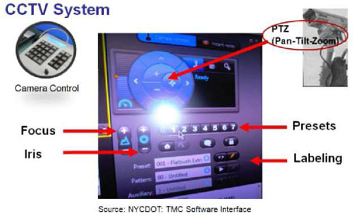
(Extended Text Description: Author's relevant notes: A graphic image shows elements of control for a CCTV System, including: pan-tilt-zoom, focus control, iris control, preset position selection, and image labeling.)

(Extended Text Description: This slide shows a Protocol Requirements List (PRL) developed in the A317a course module. Step 1: Identify User Needs. The table content is shown below:
| UN ID | User Need | Req ID | Requirement | Additional Specs. |
|---|---|---|---|---|
| 3.0 | Remote Monitoring | 3.3.3 | Status condition within the device | |
| 3.3.3.2 | Temperature | |||
| 3.3.3.2 | Pressure | |||
| 3.3.3.2 | Washer fluid | |||
| 3.3.3.3 | ID Generator |
Below the table are arrows pointing to User Needs and Requirements.)
Slide 23:
Learning Objective #5
Case Study CCTV Requirements
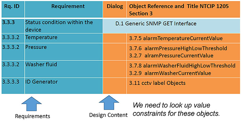
(Extended Text Description: The table content is shown below:
| Req ID | Requirement | Dialog | Object Reference and Title NTCIP 1205 Section 3 | |
|---|---|---|---|---|
| 3.3.3 | Status condition within the device | D.1 Generic SNMP GET Interface | ||
| 3.3.3.2 | Temperature | 3.7.5 alarmTemperatureCurrentValue | ||
| 3.3.3.2 | Pressure |
3.7.6 alarmPressureHighLowThreshold 3.7.7 alarmPressureCurrentValue |
||
| 3.3.3.2 | Washer fluid |
3.7.8 alarmWasherFluidHighLowThreshold 3.7.9 alarmWasherCurrentValue |
||
| 3.3.3.3 | ID Generator | 3.11 cctv label Objects | ||
Below the table are arrows pointing to Requirements and Design Content. The text "We need to look up value constraints for these objects" is to the right of the arrows.)
Step 2: Identify Requirements
Slide 24:
Dialog Example for 3.3 Status Condition within the Device
- The Object Identifier (OID) is used to make requests for data from a device
- Object data is returned in response to a SNMP GET
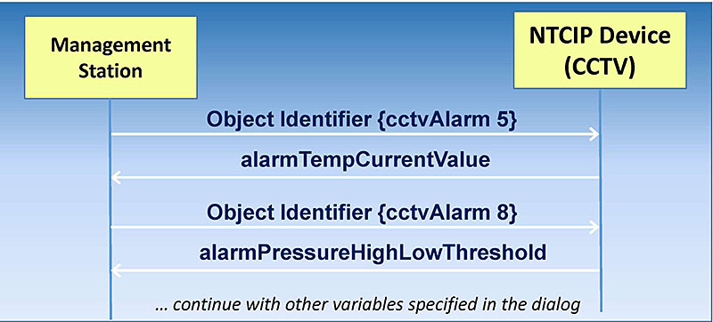
(Extended Text Description: Author's relevant notes: This slide includes a graphics display of a center-to-field communications dialog. The top of the graphic shows a management station at left and a CCTV camera at right. The image illustrates sending an object identifier (in this case cctv alarm 5) from the management station to the CCTV camera is a request. The camera responds by returning the object's value (in this case alarm temperature current value) to the management station.)
Slide 25:
Learning Objective #5
CCTV Test Case Objective and Purpose
| Test Case | |
|---|---|
| ID:TC001 | Title: Request Status Condition within the Device Dialog Verification (Positive Test Case) |
| Objective: |
To verify system interface implements (positive test case) requirements for a sequence of OBJECT requests for:
|
| Inputs: | |
| Outcome(s): | |
| Environmental Needs: | |
| Tester/Reviewer | |
| Special Procedure Requirements: | |
| Intercase Dependencies: | |
Objective
Slide 26:
Learning Objective #5
CCTV Test Case Output Specification: Data Concept ID, Data Concept Name, and Data Concept Type Filled in
| Test Case Output Specification | |||
|---|---|---|---|
| ID: TCOS001 | Title: Status Condition within the Device | ||
| Data Concept ID | Data Concept Name (Variable) | Data Concept Type | Value Constraints |
| 3.7.5 | alarmTemperatureCurrentValue | Data Element | |
| 3.7.6 | alarmPressureHighLowThreshold | Data Element | |
| 3.7.7 | alarmPressureCurrentValue | Data Element | |
| 3.7.8 | alarmWasherFluidHighLowThresh old | Data Element | |
| 3.7.9 | alarmWasherCurrentValue | Data Element | |
| 3.11 | cctv label Objects | Data Element | |
No dialogs are documented in NTCIP 1205 v01. These are simple GET/SET operations, consisting of an object request followed by the result that we will document in an output specification.
Step 4: Identify Dialogs, Inputs, Outputs
Slide 27:
Learning Objective #5
Object Definition for:
3.7.5 alarmTemperatureCurrentValue
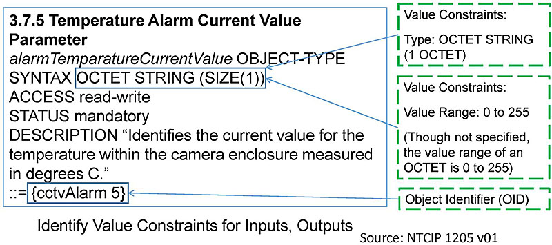
(Extended Text Description: Author's relevant notes: This slide shows an object definition for the temperature alarm current value parameter. The image highlights key information contained in the object definition relevant to the development of the test case – namely, value constraints and object identifier.)
Step 4: Identify Dialogs, Inputs, Outputs
Slide 28:
Learning Objective #5
Object Definition for:
3.7.8 alarmWasherFluidHighLowThreshold
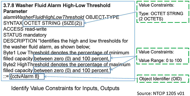
(Extended Text Description: Author's relevant notes: This slide shows an object definition for the washer fluid alarm high-low threshold parameter. The image highlights key information contained in the object definition relevant to the development of the test case – namely, value constraints and object identifier. .)
Step 4: Identify Dialogs, Inputs, Outputs
Slide 29:
Learning Objective #5
CCTV Test Case Output Specification
| Test Case Output Specification | |||
|---|---|---|---|
| ID: TCOS001 | Title: Status Condition within the Device | ||
| Data Concept ID | Data Concept Name (Variable) | Data Concept Type | Value Domain |
| 3.7.5 | alarmTemperatureCurrentValue | Data Element | OCTET STRING (SIZE(1)) - Range: 0 to 255. |
| 3.7.6 | alarmPressureHighLowThreshold | Data Element | OCTET STRING (SIZE(2)) - Range: 0 to 255 each byte Note: Byte 1 Low Threshold denotes the value of minimum pressure within the camera enclosure measured in psig, Byte2 High Threshold denotes the value of maximum pressure within the camera enclosure measured in psig |
| 3.7.7 | alarmPressureCurrentValue | Data Element | OCTET STRING (SIZE(1)) - Range: 0 to 255 |
| 3.7.8 | alarmWasherFluidHighLowThreshold | Data Element | OCTET STRING (SIZE(2)) - Range: 0 to 100 each byte. Note: Byte1 Low Threshold denotes the percentage of minimum filled capacity between zero (0) and 100 percent, Byte2 HighThreshold denotes the percentage of maximum filled capacity between zero (0) and 100 percent. |
| 3.7.9 | alarmWasherCurrentValue | Data Element | OCTET STRING (SIZE(1)) - Range: 0 to 100 |
| 3.11 | cctv label Objects | Data Element | etc. 3.11 contains numerous object definition entries. |
Step 5: Document Value Constraints for Inputs, Outputs
Slide 30:
Learning Objective #5
CCTV Test Case
| Test Case | |
|---|---|
| ID: TC001 | Title: Request Status Condition within the Device Dialog Verification (Positive Test Case) |
| Objective: |
To verify system interface implements (positive test case) requirements for a sequence of OBJECT requests for:
|
| Inputs: | The object identifier of each object requested is needed. |
| Outcome(s): | All data are returned and verified as correct per the OBJECT constraints of NTCIP 1205 v01. See Test Case Output Specification TCOS001 - Status Condition within the Device (Positive Test Case) |
| Environmental Needs: | When testing for alarm temperature current value, set up is needed to measure temperature. |
| Tester/Reviewer | M.I. |
| Special Procedure Requirements: | None |
| Intercase Dependencies: | None |
Step 6: Complete Test Case
Slide 31:
Learning Objective #5
Summary of CCTV Case Study
- Identified user needs from the PRL developed in Module A317a (Understanding User Needs for CCTV Systems Based on NTCIP 1205 Standard)
- Identified relevant requirements from the RTM developed in Module A317b (Understanding Requirements for CCTV Systems Based on NTCIP 1205 Standard)
- Identified dialogs, inputs and outputs, created a list of objects from the requirements and partially filled in a test output specification
- Identified and documented value constraints, for relevant objects from above step to completed test output specification
- Developed the test case for a non-SEP standard-CCTV
Slide 32:
Learning Objective #5
What have we learned from this case study?
We have learned that the NTCIP 1205 CCTV Standard does NOT have user needs (PRL) and requirements (RTM) and we must derive content from the PCB Module A317b CCTV and then proceed with test case development.
Using CCTV design objects, we have learned to identify and document value constraints in a test case.
MODULE 34: A317b: UNDERSTANDING REQUIREMENTS FOR CCTV SYSTEMS
BASED ON NTCIP 1205 STANDARD
(Source: StandardsTraining)
Slide 33:

Slide 34:
Learning Objective #5
Case Study 2: NTCIP 1204 v03 ESS
Background
-
Characteristics of the Standard: NTCIP 1204 v03 ESS
- NTCIP 1204 is a Center-to-Field Communications Standard
- NTCIP 1204 contains Systems Engineering content (i.e., the standard has a PRL and an RTM)
- NTCIP 1204 contains test documentation (i.e., there is an ANNEX C: Test Procedures)
-
Information Source:
- NTCIP 1204 v03 Object Definitions for ESS
Slide 35:
Learning Objective #5
Case Study ESS User Needs
Source: NTCIP 1204 v03 Protocol Requirement List (PRL).

(Extended Text Description: This slide shows a portion of the Protocol Requirements List (PRL) from NTCIP 1204 v03 ESS standard. The image highlights that user needs are on the left-hand side, and that requirements are on the right-hand side of the table.
| User Need ID | User Need | FR ID | Functional Requirement | Conformance | Project Requirement | Additional Project Requirements |
|---|---|---|---|---|---|---|
| 2.5.2.1.2 (Wind) | Monitor Winds | O.3 (1..*) | Yes / No / NA | |||
| 3.5.2.3.2.2 | Retrieve Wind Data | M | Yes / NA | |||
| 3.6.2 | Required Number of Wind Sensors | M | Yes / NA | The ESS shall support at least ___ wind sensors. | ||
)
Step 1: Identify User Needs
Slide 36:
Learning Objective #5
Case Study ESS Requirements
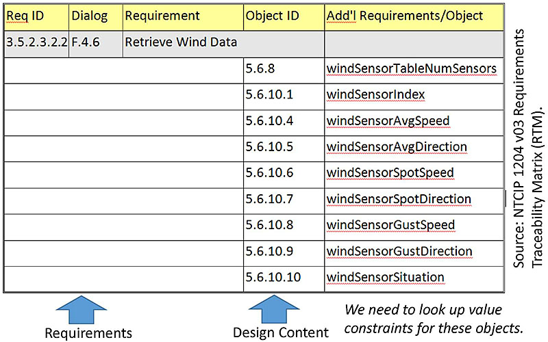
(Extended Text Description: This slide shows a portion of the Requirements Traceability Matrix (RTM) from NTCIP 1204 v03 ESS standard. The image highlights that requirements are on the left-hand side, and that design content is on the right-hand side of the table.
| Req ID | Dialog | Requirement | Object ID | Add'l Requirements/Object |
|---|---|---|---|---|
| 3.5.2.3.2.2 | F.4.6 | Retrieve Wind Data | ||
| 5.6.8 | windSensorTableNumSensors | |||
| 5.6.10.1 | windSensorIndex | |||
| 5.6.10.4 | windSensorAvgSpeed | |||
| 5.6.10.5 | windSensorAvgDirection | |||
| 5.6.10.6 | windSensorSpotSpeed | |||
| 5.6.10.7 | windSensorSpotDirection | |||
| 5.6.10.8 | windSensorGustSpeed | |||
| 5.6.10.9 | windSensorGustDirection | |||
| 5.6.10.10 | windSensorSituation | |||
)
Step 2: Identify Requirements
Slide 37:
Learning Objective #5
Discussion: Case Study ESS RTCTM

(Extended Text Description: This slide shows a portion of the Requirements to Test Case Traceability Matrix (RTM) from NTCIP 1204 v03 ESS standard. The image highlights that requirements are on the left-hand side, and that test cases used to verify the requirements are on the right-hand side of the table.
| Requirement | Test Case | ||
|---|---|---|---|
| ID | Title | ID | Title |
| 3.5.2.3.2 | Monitor Weather Condition | ||
| 3.5.2.3.2.1 | Retrieve Atmospheric Pressure | ||
| C.2.3.3.2 | Retrieve Atmospheric Pressure | ||
| 3.5.2.3.2.2 | Retrieve Wind Data | ||
| C.2.3.3.3 Retrieve Wind Data | |||
| 3.5.2.3.2.3 | Retrieve Temperature | ||
| C.2.3.3.4 | Retrieve Temperature | ||
| 3.5.2.3.2.4 | Retrieve Daily Minimum and Maximum Temperature | ||
| C.2.3.3.5 | Retrieve Daily Minimum and Maximum Temperature | ||
| 3.5.2.3.2.5 | Retrieve Humidity | ||
| C.2.3.3.6 | Retrieve Humidity | ||
)
Discussion
Slide 38:
Learning Objective #5
Discussion: Case Study ESS Test Procedure
C.2.3.3.3 Retrieve Wind Data
| Test Case: 3.3 | Title: | Retrieve Wind Data | |
| Description: | This test case verifies thai the ESS allows a management station to determine turner?? wind infonnaiion. | ||
| Variables: | Required_Wind_Sensors | PRL 3.6 2 | |
| Pass/Fail Criteria: | The device under test (DUT) shall pass every verification step included within the Test Case in order to pass the Test Case. | ||
| Step | Test Procedure | Device | |
|---|---|---|---|
| 1 | CONFIGURE: Determine the number of wind sensors required by the specification (PRL 3.6.2). RECORD this information as: Required_Wind_Sensors | ||
| 2 | GET the fo1lowing object(s): windSensorTableNumSensors.0 | Pass/Fail (Clause 3.5.2.3.2.2) | |
| 3 | VERIFY that the RESPONSE VALUE for windSensorTableNumSensors.0 is greater than or equal to Required_Wind_Sensors. | Pass/Fail (Clause 3.6.2) | |
| 4 | Determine the RESPONSE VALUE for windSensorTableNumSensors.0. RECORD this information as: Supported_Wind_Sensors | ||
| 5 | FOR EACH value, N, from 1 to Supported_Wind_Sensors, perform Steps 5.1 through 5.22. | ||
| 5.1 |
GET the following object(s):
|
Pass/Fail (Clause 3.5.2.3.2.2) | |
| 5.2 | VERIFY that the RESPONSE VALUE for wind SensorAvgSpeed.N is greater than or equal to O. | Pass/Fail (Clause 5.6.10.4) | |
Discussion
Slide 39:
Learning Objective #5
Discussion: ESS Standard's SE and Test Content Makes the Implementers' Job Easier
- Test case material is integrated into the test procedures in the ESS Standard.
- Once requirements are selected, then the design and test procedures are selected.
- What is missing from ESS and DMS, and what needs to be added, are input values and outcomes.
- For a simple device like an ESS and DMS, the NTCIP 8007 test documentation is adequate. However, this approach does not work for more complex standards such as NTCIP 1202 or TMDD. IEEE 829 is a better fit for handling more complex standards.
- Lastly, there is no direct translation between NTCIP 8007 and IEEE 829, so we continue with the steps as we've outlined for development of test cases.
Discussion
Slide 40:
Learning Objective #5
ESS Test Case Objective and Purpose
| Test Case | |
|---|---|
| ID:TC0012 | Title: Retrieve Wind Data (Positive Test Case) |
| Objective: |
To verify system interface implements (positive test case) requirements for a sequence of OBJECT requests for:
|
| Inputs: | |
| Outcome(s): | |
| Environmental Needs: | |
| Tester/Reviewer | |
| Special Procedure Requirements: | |
| Intercase Dependencies: | |
Step 3: Develop Test Case Objective
Slide 41:
Learning Objective #5
ESS Test Case Output Specification: With Data Concept ID, Data Concept Name, and Data Concept Type Filled in
| Test Case Output Specification | |||
|---|---|---|---|
| ID: TCOS022 | Title: Wind Data | ||
| Data Concept ID | Data Concept Name (Variable) | Data Concept Type | Value Domain |
| 5.6.8 | windSensorTableNumSensors | Data Element | |
| 5.6.10.1 | windSensorIndex | Data Element | |
| 5.6.10.4 | windSensorAvgSpeed | Data Element | |
| 5.6.10.5 | windSensorAvgDirection | Data Element | |
| 5.6.10.6 | windSensorSpotSpeed | Data Element | |
| 5.6.10.7 | windSensorSpotDirection | Data Element | |
| 5.6.10.8 | windSensorGustSpeed | Data Element | |
| 5.6.10.9 | windSensorGustDirection | Data Element | |
| 5.6.10.10 | windSensorSituation | Data Element | |
Step 4: Identify Dialogs, Inputs, Outputs
Slide 42:
Learning Objective #5
Object Definition for: 5.6.10.4 windSensorAvgSpeed
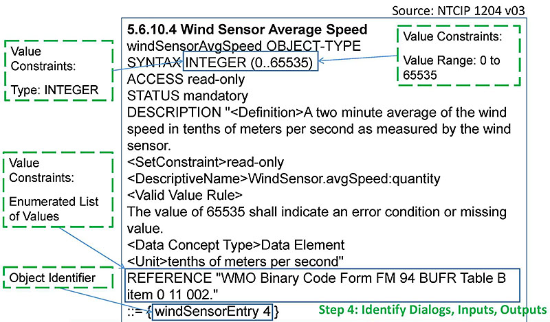
(Extended Text Description: Author's relevant notes: This slide shows an object definition for wind sensor average speed. The image highlights key information contained in the object definition relevant to the development of the test case – namely, value constraints and object identifier.)
Slide 43:
Learning Objective #5
Object Definition for: 5.6.10.10 windSensorSituation

(Extended Text Description: Author's relevant notes: This slide shows an object definition for wind sensor situation. The image highlights key information contained in the object definition relevant to the development of the test case – namely, value constraints and object identifier.)
Step 4: Identify Dialogs, Inputs, Outputs
Slide 44:
Learning Objective #5
ESS Test Case Output Specification (1 of 3)
| Test Case Output Specification | |||
|---|---|---|---|
| ID: TCOS022 | Title: Wind Data | ||
| Data Concept ID | Data Concept Name (Variable) | Data Concept Type | Value Constraints |
| 5.6.8 | windSensorTableNumSensors | Data Element | INTEGER (0..255) |
| 5.6.10.1 | windSensorIndex | Data Element | INTEGER (1..255) |
| 5.6.10.4 | windSensorAvgSpeed | Data Element | INTEGER (0..65535) tenths of meters per second WMO Binary Code Form FM 94 BUFR Table B item 0 11 002 |
| 5.6.10.5 | windSensorAvgDirection | Data Element | INTEGER (0..361) The value of zero (0) shall indicate 'calm', when the associated speed is zero (0), or 'light and variable,' when the associated speed is greater than zero (0). Normal observations, as defined by the WMO, shall report a wind direction in the range of 1 to 360 with 90 meaning from the east and 360 meaning from the north. The value of 361 shall indicate an error condition and shall always be reported if the associated speed indicates error. |
| 5.6.10.6 | windSensorSpotSpeed | Data Element | INTEGER (0..65535) tenths of meters per second The value of 65535 shall indicate an error condition or missing value. |
Step 5: Document Value Constraints for Inputs, Outputs
Slide 45:
Learning Objective #5
ESS Test Case Output Specification (2 of 3)
| Test Case Output Specification | |||
|---|---|---|---|
| ID: TCOS022 | Title: Wind Data | ||
| Data Concept ID | Data Concept Name (Variable) | Data Concept Type | Value Constraints |
| 5.6.10.7 | windSensorSpotDirection | Data Element | INTEGER (0..361) The value of zero (0) shall indicate 'calm', when the associated speed is zero (0), or 'light and variable,' when the associated speed is greater than zero (0). Normal observations, as defined by the WMO, shall report a wind direction in the range of 1 to 360 with 90 meaning from the east and 360 meaning from the north. The value of 361 shall indicate an error condition and shall always be reported if the associated speed indicates error. |
| 5.6.10.8 | windSensorGustSpeed | Data Element | INTEGER (0..65535) tenths of meters per second WMO Code Form FM 94 BUFR Table B item 0 11 041. The value of 65535 shall indicate an error condition or missing value. |
| 5.6.10.9 | windSensorGustDirection | Data Element | INTEGER (0..361) (See 5.6.10.7) |
Step 5: Document Value Constraints for Inputs, Outputs
Slide 46:
Learning Objective #5
ESS Test Case Output Specification (3 of 3)
| Test Case Output Specification | |||
|---|---|---|---|
| ID: TCOS022 | Title: Wind Data | ||
| Data Concept ID | Data Concept Name (Variable) | Data Concept Type | Value Domain |
| 5.6.10.10 | windSensorSituation | Data Element | INTEGER other (1), unknown (2), calm (3), lightBreeze (4), moderateBreeze (5), strongBreeze (6), gale (7), moderateGale (8), strongGale (9), stormWinds (10), hurricaneForceWinds (11), gustyWinds (12) (See object definition for additional detail.) |
Step 5: Document Value Constraints for Inputs, Outputs
Slide 47:
Learning Objective #5
ESS Test Case
| Test Case | |
|---|---|
| ID: TC0012 | Title: Retrieve Wind Data (Positive Test Case) |
| Objective: |
To verify system interface implements (positive test case) requirements for a sequence of OBJECT requests for:
|
| Inputs: | The object identifier of each object requested. |
| Outcome(s): | All data are returned and verified as correct per the OBJECT constraints of NTCIP 1204 v03. See Test Case Output Specification TCOS022 - Wind Data. |
| Environmental Needs: | When testing for average wind speed, an artificial wind device is needed to provide the wind for the sensor to measure. |
| Tester/Reviewer | M.I. |
| Special Procedure Requirements: | Wind simulator set-up. (See test procedures.) |
| Intercase Dependencies: | None |
Step 6: Complete Test Case
Slide 48:
Learning Objective #5
Summary of the ESS Case Study
- Identified user needs from the SEP-based NTCIP 1204 v03 PRL
- Identified relevant requirements, used the PRL to trace from user needs to requirements, and used the RTM to trace requirements to relevant design content (dialogs, and objects)
- Identified dialogs, inputs, and outputs; created a list of objects from the requirements and partially filled in a test output specification.
- Identified and documented value constraints from object definitions and completed test output specification
- Developed the Test Case for a SEP based ESS standard
Slide 49:
Learning Objective #5
What Have We Learned from This Case Study?
We have learned that the NTCIP 1204 ESS standard has SEP content : user needs (PRL)_ and requirements (RTM) and testing documentation which we can review for the test cases development.
Using ESS design objects, we have learned to identify and document value constraints and develop a test case.
MODULE 18: T313: Applying your test plan to NTCIP 1204 v03 ESS standard (Source: StandardsTraining)
Slide 50:

Slide 51:
Learning Objective #5
Which of the following standards provides testing content?
Answer Choices
- TMDD v03 C2C Standard
- NTCIP 1204 v03 ESS Standard
- NTCIP 1205 v01 CCTV Standard
- All of the above
Slide 52:
Learning Objective #5
Review of Answers
 a) TMDD v03 C2C Standard
Incorrect. This standard only provides NRTM, and no test documentation.
 b) NTCIP 1204 v03 ESS Standard
Correct! The NTCIP ESS standard has SE and testing content.
 c) NTCIP 1205 v01 CCTV Standard
Incorrect. This standard only provides design elements (objects) and no SE content and no test documentation. Our case study 1 explained this.
 d) All of the above
Incorrect. Only certain ITS standards were developed using SE content and only two have test documentation-DMS and ESS.
Slide 53:

Slide 54:
Learning Objective #5
Case Study 3: TMDD (C2C)
Background
-
Characteristics of the TMDD v3.03c Standard
- TMDD is a Center-to-Center (C2C) Communications Standard
- TMDD contains SE content (i.e., the standard has a NRTM and an RTM)
- TMDD does not contain test documentation
-
Information Sources
- TMDD v3.03c Volume I: ConOps and Requirements
- TMDD v3.03c Volume II: Design
- User Needs and Requirements are contained in the NRTM in Volume I
- Relevant Dialogs, Input and Output Definitions (Data Concepts) and RTM are contained in Volume II
Slide 55:
Learning Objective #5
Background: Context Diagram

(Extended Text Description: This slide includes an image of a center-to-center communications dialog. The top of the graphic shows an external station at left and an owner center at right. This image illustrates sending a link status request message from the external center to owner center as a request. The owner center responds by returning a link status message to the external center.)
- Positive test case for a specified sequence of messages
- linkStatusRequestMsg is used to make the request
- linkStatusMsg contains the response
Slide 56:
Learning Objective #5
Case Study TMDD Needs
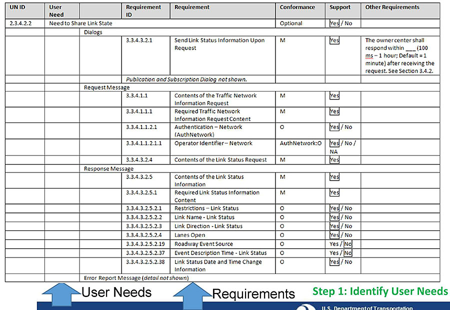
(Extended Text Description: This slide shows a portion of the Needs to Requirements Traceability Matrix (NRTM) from the TMDD standard. The image highlights that user needs are on the left-hand side, and that requirements are on the right-hand side of the table. The table contains the following content:
| UN ID | User Need | Requirement ID | Requirement | Conformance | Support | Other Requirements | |
|---|---|---|---|---|---|---|---|
| 2.3.4.2.2 | Need to Share Link State | Optional | [Yes] / No | ||||
| Dialogs | |||||||
| 3.3.4.3.2.1 | Send Link Status Information Upon Request | M | [Yes] | The owner center shall respond within ___ (100ms - 1 hour; Default = 1 minute) after receiving the request. See Section 3.4.2. | |||
| Publication and Subscription Dialog not shown. | |||||||
| Request Message | |||||||
| 3.3.4.1.1 | Contents of the Traffic Network Information Request | M | [Yes] | ||||
| 3.3.4.1.1.1 | Required Traffic Network Information Request Content | M | [Yes] | ||||
| 3.3.4.1.1.2.1 | Authentication - Network (AuthNetwork) | O | [Yes] / No | ||||
| 3.3.4.1.1.2.1.1 | Operator Identifier -Network | AuthNetwork:O | [Yes] / No / NA | ||||
| 3.3.4.3.2.4 | Contents of the Link Status Request | M | [Yes] | ||||
| Response Message | |||||||
| 3.3.4.3.2.5 | Contents of the Link Status Information | M | [Yes] | ||||
| 3.3.4.3.2.5.1 | Required Link Status Information Content | M | [Yes] | ||||
| 3.3.4.3.2.5.2.1 | Restrictions - Link Status | O | [Yes] / No | ||||
| 3.3.4.3.2.5.2.2 | Link Name - Link Status | O | [Yes] / No | ||||
| 3.3.4.3.2.5.2.3 | Link Direction - Link Status | O | [Yes] / No | ||||
| 3.3.4.3.2.5.2.4 | Lanes Open | O | [Yes] / No | ||||
| 3.3.4.3.2.5.2.19 | Roadway Event Source | O | Yes / [No] | ||||
| 3.3.4.3.2.5.2.37 | Event Description Time -Link Status | O | Yes / [No] | ||||
| 3.3.4.3.2.5.2.38 | Link Status Date and Time Change Information | O | [Yes] / No | ||||
| Error Report Message (detail not shown) | |||||||
)
Slide 57:
Learning Objective #5
Case Study TMDD Requirements
A portion of the RTM is shown, see student supplement for a full view.
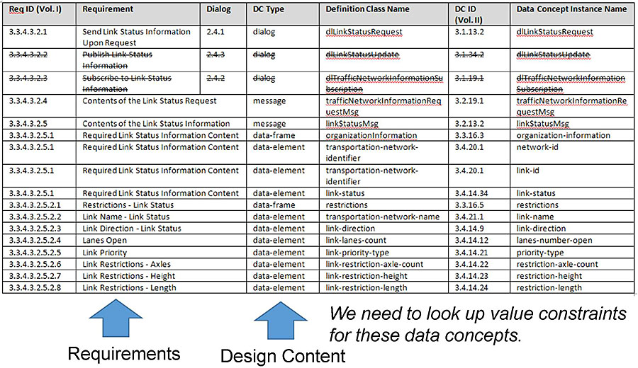
(Extended Text Description: This slide shows a portion of the Requirements Traceability Matrix (RTM) from the TMDD standard. The image highlights that requirements are on the left-hand side, and that design content is on the right-hand side of the table. The table contains the following content:
| Req ID (Vol. I) | Requirement | Dialog | DC Type | Definition Class Name | DC ID (Vol. II) | Data Concept Instance Name |
|---|---|---|---|---|---|---|
| 3.3.4.3.2.1 | Send Link Status Information Upon Request | 2.4.1 | dialog | dlLinkStatusRequest | 3.1.13.2 | dlLinkStatusRequest |
| 3.3.4.3.2.4 | Contents of the Link Status Request | message | trafficNetworkInformationRequestMsg | 3.2.19.1 | trafficNetworkInformationRequestMsg | |
| 3.3.4.3.2.5 | Contents of the Link Status Information | message | linkStatusMsg | 3.2.13.2 | linkStatusMsg | |
| 3.3.4.3.2.5.1 | Required Link Status Information Content | data-frame | organizationInformation | 3.3.16.3 | organization-information | |
| 3.3.4.3.2.5.1 | Required Link Status Information Content | data-element | transportation-network-identifier | 3.4.20.1 | network-id | |
| 3.3.4.3.2.5.1 | Required Link Status Information Content | data-element | transportation-network-identifier | 3.4.20.1 | link-id | |
| 3.3.4.3.2.5.1 | Required Link Status Information Content | data-element | link-status | 3.4.14.34 | link-status | |
| 3.3.4.3.2.5.2.1 | Restrictions - Link Status | data-frame | restrictions | 3.3.16.5 | restrictions | |
| 3.3.4.3.2.5.2.2 | Link Name - Link Status | data-element | transportation-network-name | 3.4.21.1 | link-name | |
| 3.3.4.3.2.5.2.3 | Link Direction - Link Status | data-element | link-direction | 3.4.14.9 | link-direction | |
| 3.3.4.3.2.5.2.4 | Lanes Open | data-element | link-lanes-count | 3.4.14.12 | lanes-number-open | |
| 3.3.4.3.2.5.2.5 | Link Priority | data-element | link-priority-type | 3.4.14.21 | priority-type | |
| 3.3.4.3.2.5.2.6 | Link Restrictions - Axles | data-element | link-restriction-axle-count | 3.4.14.22 | restriction-axle-count | |
| 3.3.4.3.2.5.2.7 | Link Restrictions - Height | data-element | link-restriction-height | 3.4.14.23 | restriction-height | |
| 3.3.4.3.2.5.2.8 | Link Restrictions - Length | data-element | link-restriction-length | 3.4.14.24 | restriction-length | |
)
Step 2: Identify Requirements
Slide 58:
Learning Objective #5
TMDD Test Case Objective and Purpose
| Test Case | |
|---|---|
| ID:TC001 | Title: Link Status Request-Response Dialog Verification (Positive Test Case) |
| Objective: |
To verify system interface implements (positive test case) requirements for:
|
| Inputs: | |
| Outcome(s): | |
| Environmental Needs: | |
| Tester/Reviewer | |
| Special Procedure Requirements: | |
| Intercase Dependencies: | |
Step 3: Develop Test Case Objective
Slide 59:
Learning Objective #5
Data Concept Definition for:
3.3.16.3 organizationInformation (1 of 2)
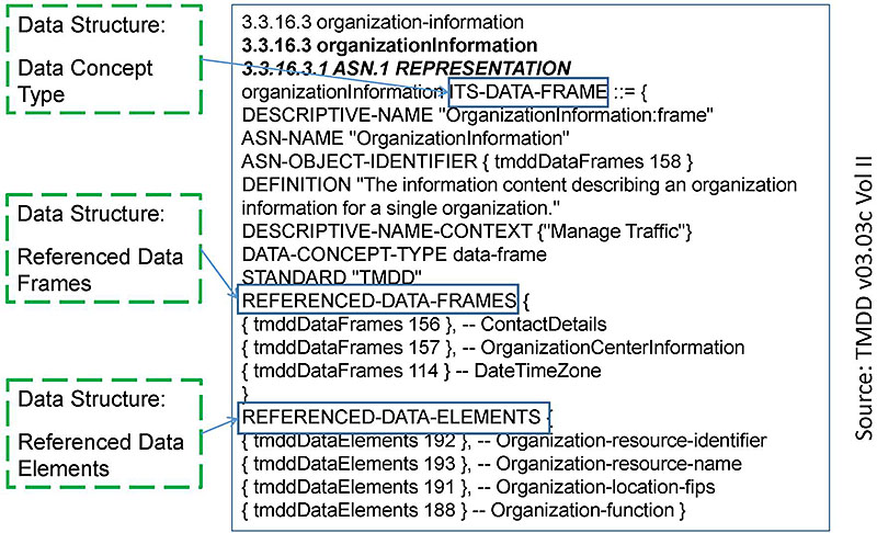
(Extended Text Description: Author's relevant notes: This slide shows a data concept definition for organization information. The image highlights key information contained in the data concept definition relevant to the development of the test case – namely, data concept type (data frame), and for data frames data structure of the data frame.)
Step 4: Identify Dialogs, Inputs, Outputs
Slide 60:
Learning Objective #5
Data Concept Definition for:
3.3.16.3 organizationInformation (2 of 2)
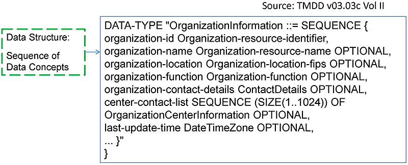
(Extended Text Description: Author's relevant notes: This slide is a continuation of the previous slide showing valid sequence of data concepts that make up the data frame.)
Step 4: Identify Dialogs, Inputs, Outputs
Slide 61:
Learning Objective #5
Data Concept Definition for: 3.4.14.34 link-status
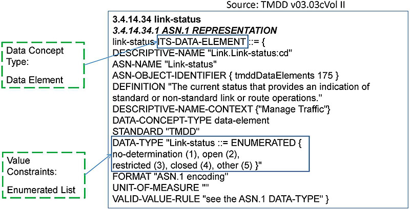
(Extended Text Description: Author's relevant notes: This slide shows a data concept definition for link status. This images highlights key information contained in the data concept definition relevant to the development of the test case – namely, data concept type (data element), and for data elements the value constraints for data.)
Step 4: Identify Dialogs, Inputs, Outputs
Slide 62:
Learning Objective #5
TMDD Test Case Input Specification
| Test Case Input Specification | |||
|---|---|---|---|
| ID: TCIS001 | Title: Input Specification for Link Status Information Request (Positive Test Case) | ||
| Data Concept ID | Data Concept Name (Variable) | Data Concept Type | Value Constraints |
| 3.2.19.1 | trafficNetworklnformationReq uestMsg | Message | |
| 3.3.16.3 | organization-requesting | Data Frame | |
| 3.4.16.8 | organization-id | Data Element | IA5String (SIZE(1..32)) |
| 3.4.16.9 | organization-name | Data Element | IA5String (SIZE(1..128)) |
| 3.4.20.2 | network-information-type | Data Element | 1 = "node inventory" 2 = "node status" 3 = "link inventory" 4 = "link status" 5 = "route inventory" 6 = "route status" 7 = "network inventory" |
Step 5: Document Value Constraints for Inputs, Outputs
Slide 63:
Learning Objective #5
TMDD Test Case Output Specification
| Test Case Output Specification | |||
|---|---|---|---|
| ID: TCOS001 | Title: Output Specification for Link Status Information Request (Positive Test Case) | ||
| Data Concept ID | Data Concept Name (Variable) | Data Concept Type | Value Constraints |
| 3.2.13.2 | linkStatusMsg | Message | |
| 3.3.16.3 | organization-information | Data Frame | |
| 3.4.16.8 | organization-id | Data Element | IA5String (SIZE(1..32)) |
| 3.4.16.9 | organization-name | Data Element | IA5String (SIZE(1..128)) |
| 3.4.20.1 | network-id | Data Element | IA5String (SIZE(1..32)) |
| 3.4.20.1 | link-id | Data Element | IA5String (SIZE(1..32)) |
| 3.4.21.1 | link-name | Data Element | IA5String (SIZE(1..128)) |
| 3.4.14.34 | link-status | Data Element | 1 = "no determination" 2 = "open" 3 = "restricted" 4 = "closed" |
| 3.4.14.37 | travel-time | Data Element | INTEGER (0..65535), units=seconds |
Step 5: Document Value Constraints for Inputs. Outputs
Slide 64:
Learning Objective #5
TMDD Test Case
| Test Case | |
|---|---|
| ID: TC001 | Title: Link Status Request-Response Dialog Verification (Positive Test Case) |
| Objective: |
To verify system interface implements (positive test case) requirements for:
|
| Inputs: | Use the input file linkStatusRequest_pos.xml. See Test Case Input Specification TCIS001 - LinkStatusRequest (Positive Test Case). Set network-information-type to 4 or the text "link status". |
| Outcome(s): | All data are returned and verified as correct: correct sequence of message exchanges, structure of data, and valid value of data content. See Test Case Output Specification TCOS001 -LinkStatusInformation (Positive Test Case) |
| Environmental Needs: | No additional needs outside of those specified in the test plan. |
| Tester/Reviewer | M.I. |
| Special Procedure Requirements: | None |
| Intercase Dependencies: | None |
Step 6: Complete Test Case
Slide 65:
Learning Objective #5
Summary of the TMDD Case Study
- Identified user needs from the TMDD NRTM Standard
- Identified relevant requirements from the TMDD NRTM (Volume I) to trace user needs to requirements and RTM (Vol II) to trace requirements to relevant design content (dialogs, and data concepts)
- Identified dialogs, inputs, and outputs and created a list of data concepts (Volume II) from the requirements and partially filled in test input and output specifications
- Identified and documented value constraints from data concept definitions and completed the test input and output specifications
- Developed the test case
Slide 66:
Learning Objective #5
Summary of Learning Objective #5
Handle Standards That Are With and Without Test Documentation
- Learn how to develop test cases where test documentation is not included in the standard: Case Study-1: NTCIP 1205 CCTV
- Learn how to develop test cases where test documentation is included in the standard: Case Study-2: NTCIP 1204 ESS
- Learn how to develop test cases where test documentation is not included in the standard: Case Study-3: TMDD (C2C)
Slide 67:
Learning Objective #6
Learning Objective #6: Develop a Requirements to Test Case Traceability Matrix (RTCTM)
- How does RTCTM fit in a test coverage?
- Discuss format of a RTCTM
- Discuss the importance of testing every requirement at least once
Slide 68:
Learning Objective #6
How Does RTCTM fit in a Test Coverage?
- Generally, test coverage can be viewed as an indication of the degree to which the test item has been "covered" by the test cases
-
The test items in the Test Case Specification (TCS) represent the requirements to be verified in the deployed system with a RTCTM
- A simple inspection that all the requirements you intend to test are accounted for in the RTCTM is sufficient
- Generally, each requirement is tested for a positive test case and a negative test case (to verify that error conditions are handled properly)
Slide 69:
Learning Objective #6
Format of an RTCTM
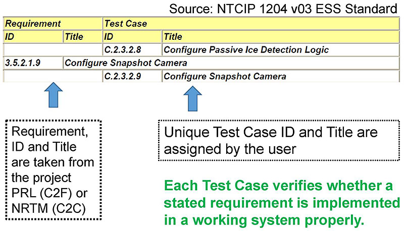
(Extended Text Description: Author's relevant notes: This slide shows a portion of the Requirements to Test Case Traceability Matrix (RTM) from NTCIP 1204 v03 ESS standard. The image highlights that requirements (Requirement, ID and Title are taken from the project PRL (C2F) ro NRTM (C2C)) are on the left-hand side, and that test cases used to verify the requirements (Unique Test Case ID and Title are assigned by the user) are on the right-hand side of the table. Each Test Case verifies whether a stated requirement is implemented in a working system properly. The table contains the following content:
| Requirement | Test Case | ||
|---|---|---|---|
| ID | Title | ID | Title |
| C.2.3.2.8 | Configure Passive Ice Detection Logic | ||
| 3.5.2.1.9 | Configure Snapshot Camera | ||
| C.2.3.2.9 | Configure Snapshot Camera | ||
)
Slide 70:
Learning Objective #6
How Each Requirement is Handled
Example:
3.5.2.1.9 Configure Snapshot Camera (From ESS PRL)
Upon request, the ESS shall store a textual description of the location to which the camera points and the filename to be used when storing new snapshots.
Relevant Objects for Value constraints (from ESS RTM)
- Object ID Add'l Requirements/Object
- 5.16.3.1 essSnapshotCameraIndex
- 5.16.3.2 essSnapshotCameraDescription
- 5.16.3.6 essSnapshotCameraFilename
RTCTM connects a Requirement ID to a Test Case ID:

(Extended Text Description: The image contains a table with the following content:
| 3.5.2.1.9 | Configure Snapshot Camera | ||
| C.2.3.2.9 | Configure Snapshot Camera | ||
)
Slide 71:
Learning Objective #6
Example of RTCTM
Source: NTCIP 1204 v03 ESS Standard
| Requirement | Test Case | ||
|---|---|---|---|
| ID | Title | ID | Title |
| C.2.3.2.8 | Configure Passive Ice Detection Logic | ||
| 3.5.2.1.9 | Configure Snapshot Camera | ||
| C.2.3.2.9 | Configure Snapshot Camera | ||
| 3.5.2.3 | Sensor Data Retrieval Requirements | ||
| 3.5.2.3.1 | Retrieve Weather Profile with Mobile Sources | ||
| C.2.3.3.1 | Retrieve Weather Profile with Mobile Sources | ||
| 3.5.2.3.2 | Monitor Weather Condition | ||
| 3.5.2.3.2.1 | Retrieve Atmospheric Pressure | ||
| C.2.3.3.2 | Retrieve Atmospheric Pressure | ||
| 3.5.2.3.2.2 | Retrieve Wind Data | ||
| C.2.3.3.3 Retrieve Wind Data | |||
| 3.5.2.3.2.3 | Retrieve Temperature | ||
| C.2.3.3.4 | Retrieve Temperature | ||
| 3.5.2.3.2.4 | Retrieve Daily Minimum and Maximum Temperature | ||
| C.2.3.3.5 | Retrieve Daily Minimum and Maximum Temperature | ||
| 3.5.2.3.2.5 | Retrieve Humidity | ||
| C.2.3.3.6 | Retrieve Humidity | ||
| 3.5.2.3.2.6 | Monitor Precipitation | ||
| 3.5.2.3.2.6.1 | Retrieve Precipitation Presence | ||
Slide 72:
Learning Objective #6
Let's Build an RTCTM for the CCTV Case Study
- Step 1: Identify Requirements.
- Step 2: Identify Test Case(s) that will verify the requirements.
- Step 3: Add a RTCTM Entry.
Slide 73:
Learning Objective #6
Build RTCTM for CCTV Case Study Requirements

(Extended Text Description: Author's relevant notes: This slide shows a portion of the RTM from the CCTV Case Study. The image highlights that the requirements we'll use to develop the RTCTM are on the left-hand side, and that design content at right may be ignored. The table contains the following content:
| Req ID | Requirement | Dialog | Object Reference and Title NTCIP 1205 Section 3 | |
|---|---|---|---|---|
| 3.3.3 | Status condition within the device | D.1 Generic SNMP GET Interface | ||
| 3.3.3.2 | Temperature | 3.7.5 alarmTemperatureCurrentValue | ||
| 3.3.3.2 | Pressure |
3.7.6 alarmPressureHighLowThreshold 3.7.7 alarmPressureCurrentValue |
||
| 3.3.3.2 | Washer fluid |
3.7.8 alarmWasherFluidHighLowThreshold 3.7.9 alarmWasherCurrentValue |
||
| 3.3.3.3 | ID Generator | 3.11 cctv label Objects | ||
)
Slide 74:
Learning Objective #6
Build RTCTM for CCTV Case Study Test Case
| Test Case | |
|---|---|
| ID:TC001 | Title: Request Status Condition within the Device Dialog Verification (Positive Test Case) |
| Objective: |
To verify system interface implements (positive test case) requirements for a sequence of OBJECT requests for:
|
| Inputs: | The object identifier of each object requested is needed. |
| Outcome(s): | All data are returned and verified as correct per the OBJECT constraints of NTCIP 1205 v01. See Test Case Output Specification TCOS001 - Status Condition within the Device (Positive Test Case) |
| Environmental Needs: | When testing for alarm temperature current value, set up is needed to measure temperature. |
| Tester/Reviewer | M.I. |
| Special Procedure Requirements: | None |
| Intercase Dependencies: | None |
Slide 75:
Learning Objective #6
Build RTCTM for CCTV Case Study
| Requirements to Test Case Traceability Matrix | |||
|---|---|---|---|
| Requirement | Test Case | ||
| ID | Title | ID | Title |
| 3.3.3 | Status Condition within the Device | ||
| TC001 | Title: Request Status Condition within the Device Dialog Verification (Positive Test Case) | ||
Slide 76:
Learning Objective #6
Importance of RTCTM
- Every ITS project's testing documentation (Test Plan) must have RTCTM included.
- RTCTM allows testing personnel to focus on each functionality (requirement), one at a time, ensuring performance as intended by the user.
- RTCTM brings users, developers, and testers on a level field for a successful outcome.
- Without RTCTM, verification-validation will NOT occur properly.
Slide 77:

Slide 78:
Learning Objective #6
The Requirements to Test Case Traceability Matrix relates to which of the following?
Answer Choices
- Requirements and design
- Test cases and requirements
- Needs and requirements
- None of the above
Slide 79:
Learning Objective #6
Review of Answers
 a) Requirements and design
Incorrect. The RTM relates requirements and design content
 b) Test cases and requirements
Correct! The RTCTM relates test cases and the requirements the test cases verify.
 c) Needs and requirements
Incorrect. The PRL or NRTM relates needs and requirements.
 d) None of the above
Incorrect. The correct answer is b) above.
Slide 80:
Learning Objective #6
Summary of Learning Objective #6
Develop a Requirements to Test Case Traceability Table (RTCTM)
- How does RTCTM fit in a test coverage?
- Discuss format of a RTCTM
- Discuss the importance of testing every requirement at least once
Slide 81:
Learning Objective #7
Learning Objective #7: Identify Types of Testing
-
Function Test
- Positive Test
- Negative Test
- Boundary Test
- Performance Test
- Load Test
- Stress Test
- Benchmark Test
- Integration Test
- System Acceptance Test
Slide 82:
Learning Objective #7
Types of Testing
Function Test
- The function test verifies that the system interprets inputs correctly, performs a desired outcome, and returns a correct response
- Positive testing invokes a system function to verify proper response
- Negative testing invokes a system error to verify that the system responds properly to errors
- The boundary tests are constructed to test the inputs and outputs of a system at the extremes in terms of value and size ranges
- The boundary test is a form of positive and negative testing
Slide 83:
Learning Objective #7
Types of Testing (cont.)
Performance Test
- Constructed to verify performance requirements of a system; for example, those specific to system timing
- Testing that verifies that round-trip communications (messaging) occurs within a specified amount of time
- Testing that verifies completion of a function within a specified amount of time; for example, a calculation or a query
- Special consideration must be given during performance testing to verify and log the start and end time of the test
Slide 84:
Learning Objective #7
Types of Testing (cont.)
Load Test
- A load test is constructed to place a demand on a system or device, and measure its response
- Load testing is performed to determine a system's behavior under both normal and anticipated peak load conditions
- Helps to identify the maximum operating capacity of an application as well as any bottlenecks, and determines which element is causing degradation
- Special consideration must be given to identification of the metrics used to measure the system's capacity
Slide 85:
Learning Objective #7
Types of Testing (cont.)
Stress Test
- A stress test is a type of load test constructed to measure the system at peak load and overload conditions
- The stress load is usually so great that error conditions are the expected result
- Special consideration may be given to system recovery, and restart after a stress load causes a system failure
Slide 86:
Learning Objective #7
Types of Testing (cont.)
Other Testing
-
Benchmark testing is used to identify that a system achieves a defined level of functionality and performance
- For example, prior to system integration testing, certain key sub-systems should achieve a certain benchmark of performance and function
-
Certification testing is a form of benchmark testing
- Special attention must be given to ensure that systems (perhaps of different vendors or agencies) are treated equally during the test. A summary benchmark score may be used to rank results
Slide 87:
Learning Objective #7
Types of Testing (cont.)
Other Testing: Integration Tests
- Used to test how well system elements work together as a whole
- Used to test operation of system elements when other system elements are not working properly or absent
- Special consideration may be given to document results of how well the system operates under degraded operation (i.e., one or more sub-system elements has stopped working or is absent)
Slide 88:
Learning Objective #7
Types of Testing (cont.)
Other Testing: System Acceptance Tests
- Test cases can be used to verify the functions and performance of a system
- Special consideration may be given to the parties that must attend, witness, and sign-off on the test
- Disputes related to payment may be avoided if proper witnessing and sign-off on acceptance testing is documented properly
Slide 89:

Slide 90:
Learning Objective #7
Which of the following is used to test error handling of a system?
Answer Choices
- System acceptance test
- Negative test
- Periodic maintenance test
- Unit test
Slide 91:
Learning Objective #7
Review of Answers
 a) System acceptance test
Incorrect. This test is not intended specifically to test for error handling.
 b) Negative test
Correct! A negative test is designed to test error handling by the system.
 c) Periodic maintenance test
Incorrect. This test is not intended specifically to test for error handling.
 d) Unit test
Incorrect. This is a function test to a subsystem or unit of the system.
Slide 92:
Learning Objective #7
Summary of Learning Objective #7
Identify Types of Testing
-
Function Test
- Positive Test
- Negative Test
- Boundary Test
- Performance Test
- Load Test
- Stress Test
- Benchmark Test
- Integration Test
- System Acceptance Test
Slide 93:
Learning Objective #8
Learning Objective #8: Recognize the Purpose of the Test Log and Test Anomaly Reports
- Outline test reporting guidance by IEEE 829-2008
-
Discuss the test log:
- Identify data, information, and files; signatures need to be captured during the test
-
Discuss test anomaly report:
- Identify what failed and investigation necessary to provide quality feedback to system developers/maintainers
- More detailed information is provided in Module T204: How to Develop Test Procedures for an ITS Standards-based Test Plan
Slide 94:
Learning Objective #8
Impacts of Failure of a Test Case
- Ideally, your test plan will include language to describe what investigation should occur in the event of a failure or error
- In the event of a failure relatable to a test case, test anomaly report should include specific details
- In many cases, the test engineers and/or developers of the system being tested and who are present during the test will have a sense of where the problem lies, and will be able to investigate and quickly isolate the problem, describe it, and hand off the problem to development staff
- Other cases may involve a more prolonged investigation into the nature of the problem
Slide 95:
Learning Objective #8
Test Log
- The purpose of the test log is to provide a chronological record of relevant details about the execution of tests
- Capture data, information files used, and locations
- Date and times of execution of tests
- The test plan should spell out the detail of what should be logged
Slide 96:
Learning Objective #8
Test Anomaly Report
- Test anomaly report documents any event that occurs during the testing process that requires investigation (Previous IEEE 829 version called it incident report)
- We can also refer to test anomaly report as a problem, test incident, defect, trouble, issue, anomaly, or error report
Slide 97:
Learning Objective #8
Summary of Learning Objective #8
Understand the Purpose of the Test Log and Test Anomaly Reports
- Outline test reporting guidance by IEEE Std 829-2008
-
Discuss the test log:
- Identify data, information, and files; signatures need to be captured during the test
-
Discuss test anomaly report:
- Identify what failed and investigation necessary to provide quality feedback to system developers/maintainers
Slide 98:
What We Have Learned
- Showed that some standards have, test documentation, some do not, and how to deal with the gaps.
- Showed elements of a requirements to test case traceability matrix and how it can be structured to account for all requirements and all test cases.
-
Learned how to document and handle impact of test case failures.
- What to document in the test log.
- What to document in the test anomaly report.
- Learned about types of testing.
Slide 99:
What We Have Learned (cont.)
5. Process to gather information and develop a test case:
- Identify user needs
- Identify requirements
- Develop test case objective
- Identify design content
- Document value constraints
- Complete test case
Slide 100:
What We Have Learned (cont.)
6. Test reports for documenting test case failure
- Test log
- Test anomaly report
Slide 101:
What We Have Learned (cont.)
7. Test cases can be re-used in different types of testing:
- Function test
- Performance test
- Load test
- Stress test
- Benchmark test
- Integration test
- System acceptance test
Slide 102:
Resources
- IEEE Std 829-2008 IEEE Standard for Software and System Test Documentation
- IEEE Std 610-1990 Standard Glossary of Software Engineering Terminology
- NTCIP 8007 Testing and Conformity Assessment Documentation within NTCIP Standards Publications
- A317a: Understanding User Needs for CCTV Systems Based on NTCIP 1205 Standard
- A317b: Understanding Requirements for CCTV Systems Based on NTCIP 1205 Standard
- NTCIP 1205 v01 CCTV Standard
- NTCIP 1204 v03 Environmental Sensor Station Interface Standard
- Traffic Management Data Dictionary Version 3.03
- PCB Testing Modules: T311 DMS; T313 ESS; and T321 TMDD
- Student Supplement (Combined for Part 1 and 2).
Slide 103:
