Module 48 - T204 Part 2 of 2
T204 Part 2 of 2: How to Develop Test Procedures for an ITS Standards-Based Test Plan
HTML of the PowerPoint Presentation
(Note: This document has been converted from a PowerPoint presentation to 508-compliant HTML. The formatting has been adjusted for 508 compliance, but all the original text content is included, plus additional text descriptions for the images, photos and/or diagrams have been provided below.)
Slide 1:
(Extended Text Description: Welcome - Graphic image of introductory slide. A large dark blue rectangle with a wide, light grid pattern at the top half and bands of dark and lighter blue bands below. There is a white square ITS logo box with words "Standards ITS Training" in green and blue on the middle left side. The word "Welcome" in white is to the right of the logo. Under the logo box is the logo for the U.S. Department of Transpotation, Office of the Assistant Secretary for Research and Technology.)
Slide 2:

(Extended Text Description: This slide, entitled "Welcome" has a photo of Ken Leonard, Director, ITS Joint Program Office, on the left hand side, with his email address, Ken.Leonard@dot.gov. A screen capture snapshot of the home webpage is found on the right hand side - for illustration only - from August 2014. Below this image is a link to the current website: www.its.dot.gov/pcb - this screen capture snapshot shows an example from the Office of the Assistant Secretary for Research and Development - Intelligent Transportation Systems Joint Program Office - ITS Professional Capacity Building Program/Advanced ITS Education. Below the main site banner, it shows the main navigation menu with the following items: About, ITS Training, Knowledge Exchange, Technology Transfer, ITS in Academics, and Media Library. Below the main navigation menu, the page shows various content of the website, including a graphic image of professionals seated in a room during a training program. A text overlay has the text Welcome to ITS Professional Capacity Building. Additional content on the page includes a box entitled What's New and a section labeled Free Training. Again, this image serves for illustration only. The current website link is: https://www.its.dot.gov/pcb.)
Slide 3:

Slide 4:
T204 Part 2 of 2: How to Develop Test Procedures for an ITS Standards-Based Test Plan
Slide 5:
Instructor

Dave Miller,
Chair: NEMA / AASHTO / ITE Joint Committee on ATC
Chair: 3TS Technical Committee
Principal Systems Engineer
Siemens Industry, Inc.
RC-US MO MM-ITS R&D
Austin, Texas, USA
Slide 6:
Target Audience
- Test personnel responsible for developing Test Procedures
- Maintenance staff using Test Procedures for trouble shooting
- System developers
- Procurement
- Private and public sector users, including manufacturers
Slide 7:
Recommended Prerequisites
- T101: Introduction to ITS Standards Testing
- T201: How to Write a Test Plan
- T202: Overview of Test Design Specifications, Test Case Specifications, and Test Procedures
- T203 Part 1 of 2: How to Develop Test Cases for an ITS Standards-Based Test Plan, Part 1 of 2
- T203 Part 2 of 2: How to Develop Test Cases for an ITS Standards-Based Test Plan, Part 2 of 2
- T204 Part 1 of 2: How to Develop Test Procedures for an ITS Standards-Based Test Plan, Part 1 of 2
Slide 8:
Curriculum Path (Testing)
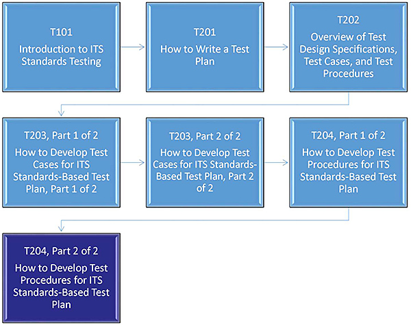
(Extended Text Description: Curriculum Path: A graphical illustration indicating the sequence of training modules that lead up to and follow each course. Each modules is represented by a box with the name of the module in it and an arrow showing the logical flow of the modules and the current module highlighted. This slide focuses on the modules that lead up to the current course. The top row of three boxes are labeled T101, T201 and T301 respectfully from left to right along with the course name for each below the course number. The second row of three boxes are labeled T203 Part 1 of 2, T203 Part 2 of 2 and T204 Part 1 of 2 respectfully from left to right along with the course name for each below the course number. The third row consists of one box labeled T204 Part 2 of 2 in the left-most column along with its course name below the course number.)
Slide 9:
abbrs and Terminology Used
| Term / abbr | Definition |
|---|---|
| C2F | Center-to-Field |
| DMS | Dynamic Message Sign |
| MIB | Management Information Base |
| MSO | Manufacturer Specific Object |
| RTCTM | Requirements to Test Case Traceability Matrix |
| RTM | Requirements Traceability Matrix |
| TCS | Test Case Specification |
| TDS | Test Design Specification |
| TMDD | Traffic Management Data Dictionary |
| TP | Test Plan |
| TPG | Test Procedure Generator |
| TPRTM | Test Procedure to Requirements Traceability Matrix |
| TPS | Test Procedure Specification |
Slide 10:
Learning Objectives
Part 1 of 2
- Recognize the purpose and structure of a test procedure
- Identify the role of a Test Procedure Specification (TPS) within a test plan and the overall testing process
- Synchronize the test procedure specification to the contract terms and conditions for successful contract execution
- Write the reports produced at the end of testing and understand their relationship to successful procurement contracts
- Use tools to develop the test procedures for a sample TPS structure
Part 2 of 2
- Use the Test Procedure Generator (TPG) to generate test procedures for a variety of equipment
- Adapt the generated test procedures to procurement contract terms and conditions for successful project conclusion
- Develop complex test procedures that pull together National Transportation Communications for Intelligent Transportation Systems Protocol (NTCIP) elements using the TPG
Slide 11:
What We Have Learned in Part 1
- Test Procedure Specification (TSP) inputs are test cases used to create outputs of expected results and anomaly reports of unexpected results in IEEE 829 standard format.
- A test design specification details what a test is to demonstrate; a test case specification specifies inputs, predicted results, and conditions, while a test procedure defines the steps to perform the test.
- Contract Terms and Conditions should be viewed from the project's end, including test case specifications and test procedures.
- A master test report measures project success to stated goals.
- Test Procedure Generator (TPG) is an automated tool that generates XML scripts using consistent key words for interoperability.
Slide 12:
Part 1 Discussed the Role of TPS Within Test Plan & Testing Process
Reviewed Test Workflow Steps
- Overall test plan
- Test Design Specification (TDS)
- Multiple test cases per test design specification
-
Multiple test procedures
- Each test procedure may cover one independent test case
- Each test procedure may cover multiple dependent test cases
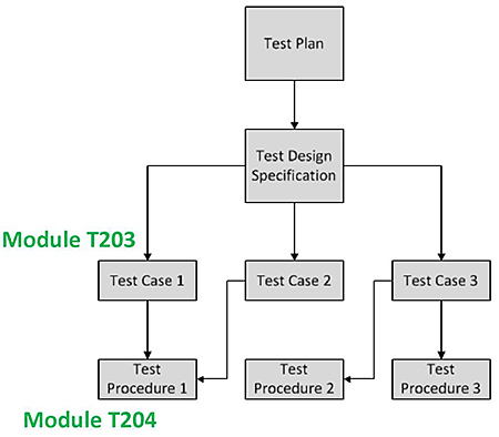
(Extended Text Description: The figure depicts the testing flowchart consisting of Test Plan box at the top with a downward arrow to Test Design Specification box. That box has three arrows directed towards three boxes labeled Test Case 1, Test Case 2 and Test Case 3 that are arranged in a horizontal row below. Test Case 1 box has one arrow directed to Test Procedure 1 box below. Test Case 2 box has one arrow directed to Test Procedure 1 box below. Test Case 3 box has two arrows. The first arrow is directed to Test Procedure 2 box, while the second arrow is directed to Test Procedure 3 box. The horizontal row of Test Case boxes is identified by the text Module 203. The horizontal row of Test Procedure boxes is identified by the text Module 204.)
Slide 13:
Learning Objective #6: Use the Test Procedure Generator (TPG) to Generate Test Procedures for a Variety of Equipment
- NTCIP 8002 Annex B1
- Role of TPG
- TPG successful installation
- Example test procedures for NTCIP 1203 v03 Dynamic Message Sign (DMS)
Slide 14:
Learning Objective #6
NTCIP 8002 Annex B1 Guidance
-
NTCIP 8002 Annex B1 defines content outline and clause numbering
- Section numbering
- Clause and subclause numbering
- Annex numbering
- Clause and subclause subject content
- Labels and tags used with each subclause
- Applicable to NTCIP 12xx-series Device Data Dictionary Standards
Slide 15:
Learning Objective #6
Role of Test Procedure Generator
- The TPG guides the development of test procedures for selected requirements in NTCIP Center-to-Field (C2F) Standards
- NTCIP C2F Standards developers can import their draft standard into the TPG to see a report of noncompliance to NTCIP 8002 Annex B1
- The report identifies breaks in traceability between requirements and design detail
| Name | Mnemonic | Specification Number | Version Number | Source |
|---|---|---|---|---|
| Microsoft Windows 7 Operation System | Windows 7 SP 1 | Service Pack 1 | 2009 | Microsoft Corp |
| Microsoft Word 2010, Professional Edition | Word 2010 | 14.0.7128.5000 or greater 32-bit | Microsoft Word 2010, Professional Edition | Microsoft Corp |
Slide 16:
Learning Objective #6
TPG Successful Installation
TPG Shortcut, NTCIP Standards, and Test Procedure Directories

Center-to-Field (C2F) Test Procedure Generator (TPG)
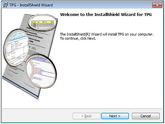
(Extended Text Description: TPG InstallShield Wizard screenshot is shown. The banner at the top of the InstallShield screenshot is "TPG – InstallShield Wizard". Below the banner is "Welcome to the InstallShield Wizard for TPG" Next line below is "TheInstallShield Wizard will install TPB on your computer. To continue, click Next". At the bottom of the screen are located "Next" and "Cancel" selection buttons. The left area of the screenshot is occupied by a graphic depicting the cover of a typical NTCIP standard title page that is enlarged in three places by magnifying glasses. Both the logo and screenshot were taken with permission from Center-to-Field Test Procedure Generator User Manual, v2.0, FHWA, July 15, 2015.)
-
C:\NTCIP Standards
- Default Directory where TPG looks for the NTCIP Standards
-
C:\Set of Test Procedures
- Default directory where TPG loads and stores test procedures
Source: Center-to-Field Test Procedure Generator User Manual, v2.0, FHWA, July 15, 2015
Slide 17:
Learning Objective #6
TPG Successful Installation (cont.)
TPG Graphical User Interface (GUI)
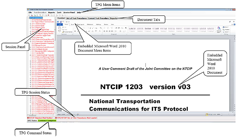
(Extended Text Description: Author's relevant description: The Graphical User Interface (GUI) screenshot is shown, consisting of a Microsoft Windows 7 screen with TPG pulldown menu items on the top banner. These pulldown menu items from left to right are "File", "Test Procedure", "Reports", "Tools", "Session Panel" and "Help" button selections. The left side of the GUI screenshot consists of the vertical "Session Panel" with a list of each item pertaining to the selected standard. Below the TPG menu items are document tabs consisting of "Standard", "Set of Test Procedures", "Current Test Procedure" and "Reports", followed by Embedded Microsoft Word 2010 Document Menu Items consisting of "File", "Home", "Insert Page Layout", "References", "Mailings", "Review" and "View" button selections. Below and to the left of the Session Panel is a main screen area with a sample NTCIP 1203 version v03 title page. Below the title page is a horizontal TPG session status text area. At the bottom is the TPG Command status text area. This GUI layout will be referenced in the later slides. Note that the course presentation does not address each item shown in each area of each screenshot; rather, the relevant pull-down buttons are described along with their effect so that the student is aware of the major GUI functions. Likewise, this description also describes the same pulldown button operation without describing each item shown on the screen. The TPG Graphical User Interface screenshot is shown taken with permission from Center-to-Field Test Procedure Generator User Manual, v2.0, FHWA, July 15, 2015.)
Source: Center-to-Field Test Procedure Generator User Manual, v2.0, FHWA, July 15, 2015
Slide 18:
Learning Objective #6
Example Test Procedure
Reset the TPG Environment

(Extended Text Description: Author's relevant description: Screenshot of the TPG GUI showing the "Tools" button pulled down with the "Option", followed by "Reset Default TPG Settings" selected. "Reset the TPG Environment" screenshot is shown taken with permission from Center-to-Field Test Procedure Generator User Manual, v2.0, FHWA, July 15, 2015.)
-
"Tools -> Options -> Reset Default TPG Settings" resets:
- Standard number used
- Major Version
- Minor Version
- Revision Letter
- NTCIP Standard Default File Path
- Set of Test Procedures Default File Path
Source: Center-to-Field Test Procedure Generator User Manual, v2.0, FHWA, July 15, 2015
Slide 19:
Learning Objective #6
Example Test Procedure (cont.)
Begin a New TPG Session

(Extended Text Description: Author's relevant description: Screenshot of the TPG GUI showing the "File" button pulled down with the "New Session" selection highlighted. Overlapping and to the right is a rectangular box with a description of the button operation. "Begin a New TPG Session" screenshot is shown taken with permission from Center-to-Field Test Procedure Generator User Manual, v2.0, FHWA, July 15, 2015.)
-
"File -> New Session":
- Define and Open the NTCIP C2F Standard to be used
Source: Center-to-Field Test Procedure Generator User Manual, v2.0, FHWA, July 15, 2015
Slide 20:
Learning Objective #6
Example Test Procedure (cont.)
Select the C2F Standard
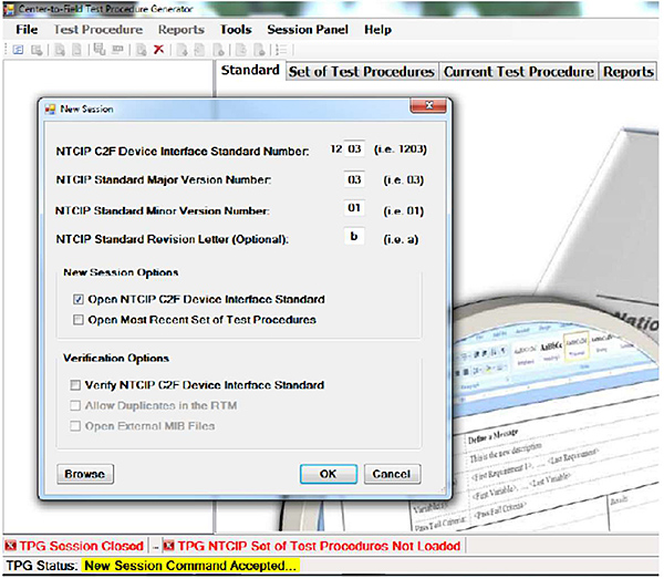
(Extended Text Description: Author's relevant description: Screenshot of the TPG GUI showing a popup screen titled "New Session". Below that banner are four data entry boxes to select the standard and version. Below are two selections for "New Session Options". Below are three selections for "Verification Options". At the bottom of the popup screen are buttons for Browse, OK and Cancel. Below the popup and at the bottom of the GUI is a text field stating the TPG Status. Again, we do not go into detail of each text string shown, only the location and function of that screen. Select the C2F Standard screenshot is shown taken with permission from Center-to-Field Test Procedure Generator User Manual, v2.0, FHWA, July 15, 2015.)
Source: Center-to-Field Test Procedure Generator User Manual, v2.0, FHWA, July 15, 2015
Slide 21:
Learning Objective #6
Example Test Procedure (cont.)
Processing the Entries
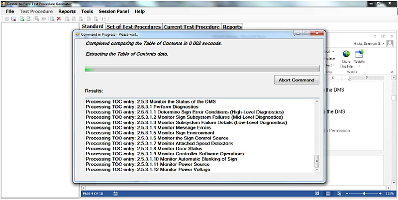
(Extended Text Description: Author's relevant description: Screenshot of the TPG GUI showing a popup screen titled "Command in Progress, Please wait" Below that banner the popup screen depicts a green horizontal bar graph showing the progress, with the processing results listed in a table below that bar graph. "Processing the Entries" screenshot is shown taken with permission from Center-to-Field Test Procedure Generator User Manual, v2.0, FHWA, July 15, 2015.)
Source: Center-to-Field Test Procedure Generator User Manual, v2.0, FHWA, July 15, 2015
Slide 22:
Learning Objective #6
Example Test Procedure (cont.)
Map NTCIP 8002 Annex B1 Required Sections

(Extended Text Description: Author's relevant description: Screenshot of the TPG "Map NTCIP 8002 Annex B1 Required Sections". The left of the screenshot shows a list of six radio buttons to select Dialogs. The right of the screenshot shows the NTCIP C2F Table of Contents for that standard. Again, the format and use of the screen is shown without a detailed description of the text shown. "Map NTCIP 8002 Annex B1 Required Sections" is shown taken with permission from Center-to-Field Test Procedure Generator User Manual, v2.0, FHWA, July 15, 2015.)
Source: Center-to-Field Test Procedure Generator User Manual, v2.0, FHWA, July 15, 2015
Slide 23:
Learning Objective #6
Example Test Procedure (cont.)
Map NTCIP 8002 Annex B1 Undefined Sections
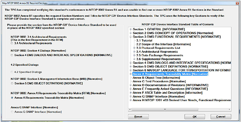
(Extended Text Description: Author's relevant description: Screenshot of the TPG "Map NTCIP 8002 Annex B1 Required Sections" is repeated as an example of using the TPG to select undefined sections. The left of the screenshot shows a list of six radio buttons to select dialogs. The right of the screenshot shows the NTCIP C2F Table of Contents. Annex A is selected and highlighted in blue on the right side. "Reset", "OK" and "Cancel" buttons occupy the horizontal area at the bottom of the GUI. "Map NTCIP 8002 Annex B1 Undefined Sections" is shown taken with permission from Center-to-Field Test Procedure Generator User Manual, v2.0, FHWA, July 15, 2015.)
Source: Center-to-Field Test Procedure Generator User Manual, v2.0, FHWA, July 15, 2015
Slide 24:
Learning Objective #6
Example Test Procedure (cont.)
Create Requirements Traceability Matrix (RTM)
- TPG verifies the content of the mapping, then constructs the RTM
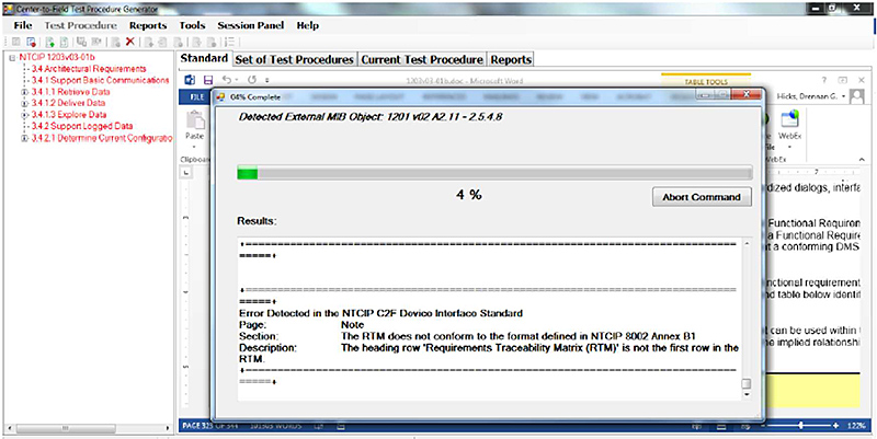
(Extended Text Description: Author's relevant description: Screenshot of the TPG GUI showing a popup screen with the banner "4% Complete" at the top. The top third of the popup depicts a green horizontal bar showing 4% complete. Below is a text area to report errors created during the progress. Again, we do not describe the Error text shown, only that the box displays errors that occur during the execution of that command. "Create Requirements Traceability Matrix" is shown taken with permission from Center-to-Field Test Procedure Generator User Manual, v2.0, FHWA, July 15, 2015.)
Source: Center-to-Field Test Procedure Generator User Manual, v2.0, FHWA, July 15, 2015
Slide 25:

Slide 26:
Learning Objective #6
How does TPG relate to NTCIP 8002?
Answer Choices
- Draft standards are verified to NTCIP 8002 compliance
- Unbroken traceability from requirements through testing
- Uniformity of test procedure content and numbering
- All of the above
Slide 27:
Learning Objective #6
Review of Answers
 a) Draft standards are verified to NTCIP 8002 compliance
Incorrect All are true.
 b) Unbroken traceability from requirements through testing
Incorrect All are true.
 c) Uniformity of test procedure content and numbering
Incorrect. All are true.
 d) All of the above
Correct! All of the above answers describe how the TPG relates to NTCIP 8002.
Slide 28:
Learning Objective #6
Example: Test Procedure for a DMS
Open the NTCIP 1203 v03 DMS Standard

(Extended Text Description: Author's relevant description: Screenshot of the TPG GUI with NTCIP 1203-01b title page shown. "Open the NTCIP 1203 v03 DMS Standard" screenshot is shown taken with permission from Center-to-Field Test Procedure Generator User Manual, v2.0, FHWA, July 15, 2015.)
Source: Center-to-Field Test Procedure Generator User Manual, v2.0, FHWA, July 15, 2015
Slide 29:
Learning Objective #6
Example: Test Procedure for a DMS (cont.)
Create a New Set of Test Procedures
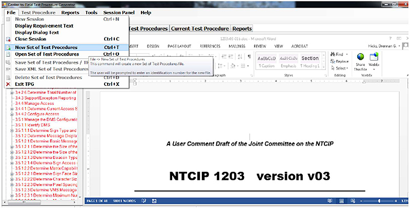
(Extended Text Description: Author's relevant description: Screenshot of the TPG GUI with NTICP 1203-01b title page shown from the previous slide, but with the addition of the "File" pull down menu open and "New Set of Test Procedures" line selected in blue. "Create a New Set of Test Procedures" screenshot is shown taken with permission from Center-to-Field Test Procedure Generator User Manual, v2.0, FHWA, July 15, 2015.)
Source: Center-to-Field Test Procedure Generator User Manual, v2.0, FHWA, July 15, 2015
Slide 30:
Learning Objective #6
Example Test Procedure for a DMS (cont.)
Create Test Procedure Requirements Traceability Matrix
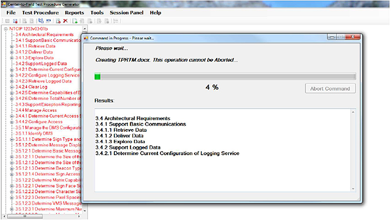
(Extended Text Description: Author's relevant description: Screenshot of the TPG GUI is shown depicting a popup screen with banner stating "Command in Progress – Please wait." Below is a horizontal green bar depicting the progress in creating a TPRTM.doc file of 4%. Below is shown a list of results. Again, we do not describe the Results text shown, only that the box displays Results that occur during the execution of that command "Create Test Procedure Requirements Traceability Matrix" screenshot is shown taken with permission from Center-to-Field Test Procedure Generator User Manual, v2.0, FHWA, July 15, 2015.)
Source: Center-to-Field Test Procedure Generator User Manual, v2.0, FHWA, July 15, 2015
Slide 31:
Learning Objective #6
Example Test Procedure for a DMS (cont.)
Set of Test Procedures
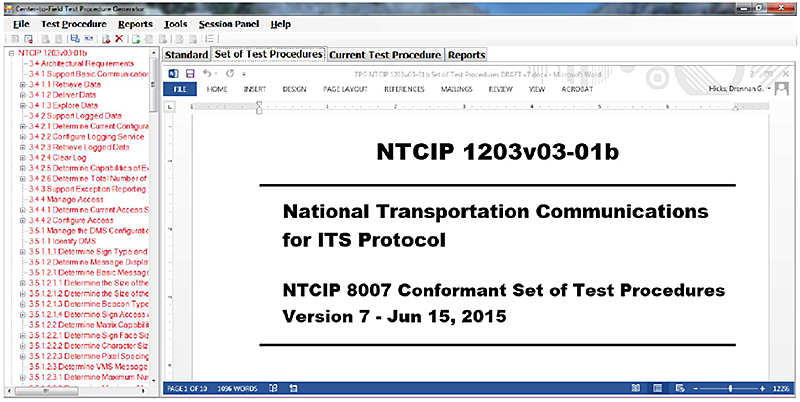
(Extended Text Description: Author's relevant description: Screenshot of the TPG graphical GUI with NTCIP 1203-01b title page is again shown, but with the "Set of Test Procedures" tab selected. "Set of Test Procedures" screenshot is shown taken with permission from Center-to-Field Test Procedure Generator User Manual, v2.0, FHWA, July 15, 2015.)
Source: Center-to-Field Test Procedure Generator User Manual, v2.0, FHWA, July 15, 2015
Slide 32:
Learning Objective #6
Example Test Procedure for a DMS (cont.)
Create a New Test Procedure
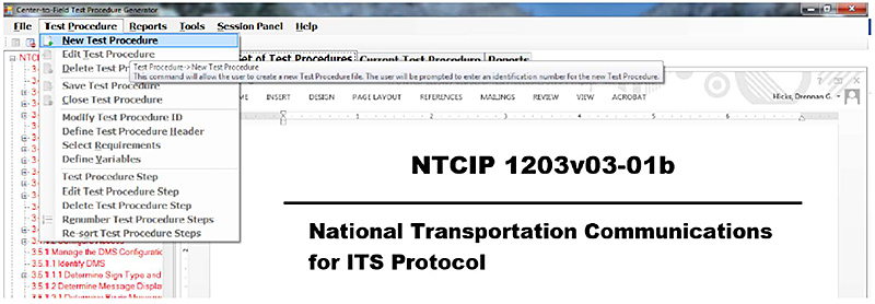
(Extended Text Description: Author's relevant description: Screenshot of the TPG GUI with NTICP 1203-01b title page shown from the previous slide, with the addition of the "Test Procedure" pull down menu open and "New Test Procedure" line selected in blue. "Create a New Test Procedure" screenshot is shown taken with permission from Center-to-Field Test Procedure Generator User Manual, v2.0, FHWA, July 15, 2015.)
Source: Center-to-Field Test Procedure Generator User Manual, v2.0, FHWA, July 15, 2015
Slide 33:
Learning Objective #6
Example Test Procedure for a DMS (cont.)
Test Procedure ID

(Extended Text Description: Author's relevant description: Screenshot of the TPG GUI is shown, with a popup screen with banner at the top labeled "Test Procedure ID". Below is a fill-in box with the ID number. In this case, the Test Procedure ID has been defaulted to "01.00". "Test Procedure ID" screenshot is shown, taken with permission from Center-to-Field Test Procedure Generator User Manual, v2.0, FHWA, July 15, 2015.)
Source: Center-to-Field Test Procedure Generator User Manual, v2.0, FHWA, July 15, 2015
Slide 34:
Learning Objective #6
Example Test Procedure for a DMS (cont.)
Test Procedure File

(Extended Text Description: Author's relevant description: Screenshot of the TPG GUI is shown. The embedded MS Word document depicts a two-column table with "Test Procedure 01.00" in the upper left table entry and all other table entry text is grayed out. "Test Procedure File" screenshot is shown taken with permission from Center-to-Field Test Procedure Generator User Manual, v2.0, FHWA, July 15, 2015.)
Source: Center-to-Field Test Procedure Generator User Manual, v2.0, FHWA, July 15, 2015
Slide 35:
Learning Objective #6
Example Test Procedure for a DMS (cont.)
Test Procedure Header
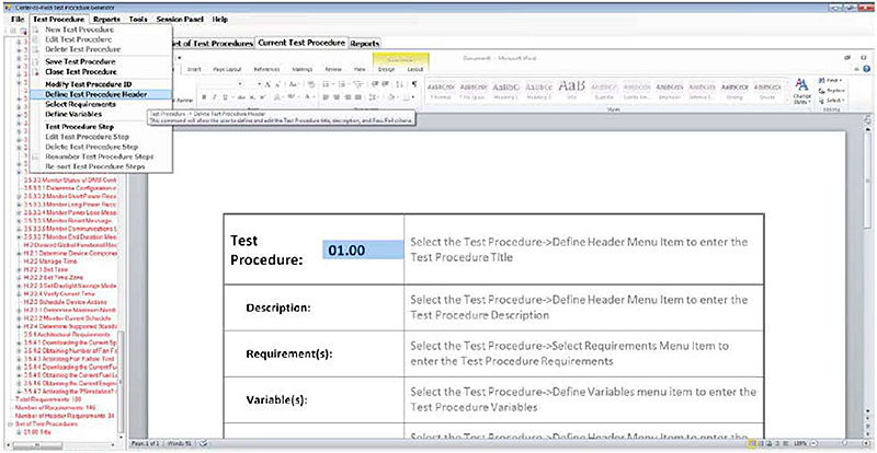
(Extended Text Description: Author's relevant description: Screenshot of the TPG GUI is shown. The embedded MS Word document depicts a two-column table with "Test Procedure 01.00" in the upper left table entry as in the previous slide. "Test Procedure" menu is pulled down and "Define Test Procedure Header" is selected in blue. "Test Procedure Header" screenshot is shown taken with permission from Center-to-Field Test Procedure Generator User Manual, v2.0, FHWA, July 15, 2015.)
Source: Center-to-Field Test Procedure Generator User Manual, v2.0, FHWA, July 15, 2015
Slide 36:
Learning Objective #6
Example Test Procedure for a DMS (cont.)
Populate the Test Procedure Header
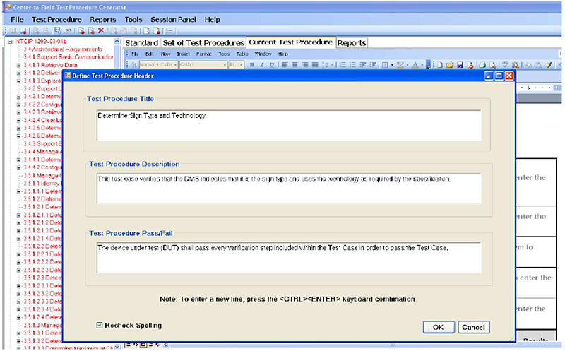
(Extended Text Description: Author's relevant description: Screenshot of the TPG GUI is shown with a popup screen "Define Test Procedure Header" popup includes three data entry boxes labeled "Test Procedure Title", "Description" and "Pass/Fail respectively". "OK" and "Cancel" buttons occupy the lower right corner horizontally arranged. Again, we do not describe the Test Procedure text shown, only that the box allows entry of Test Procedure information. "Populate the Test Procedure Header" screenshot is shown taken with permission from Center-to-Field Test Procedure Generator User Manual, v2.0, FHWA, July 15, 2015.)
Source: Center-to-Field Test Procedure Generator User Manual, v2.0, FHWA, July 15, 2015
Slide 37:
Learning Objective #6
Example Test Procedure for a DMS (cont.)
Populate the Test Procedure Header
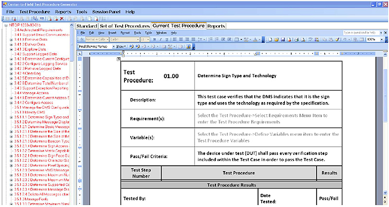
(Extended Text Description: Author's relevant description: Screenshot of the TPG GUI is shown. The embedded MS Word document depicts the same two-column table with "Test Procedure 01.00" in the upper left table entry, but now with the "Description" and "Pass/Fail Criteria" data entries populated instead of grayed out. "Continuation of Populate the Test Procedure Header" screenshot is shown taken with permission from Center-to-Field Test Procedure Generator User Manual, v2.0, FHWA, July 15, 2015.)
Source: Center-to-Field Test Procedure Generator User Manual, v2.0, FHWA, July 15, 2015
Slide 38:
Learning Objective #6
Example Test Procedure for a DMS (cont.)
Select the Requirements

(Extended Text Description: Author's relevant description: Screenshot of the TPG GUI is shown. The embedded MS Word document is shown identical to previous slide. "Test Procedure" is pulled down and "Select Requirements" is selected in blue. "Select the Requirements" screenshot is shown taken with permission from Center-to-Field Test Procedure Generator User Manual, v2.0, FHWA, July 15, 2015.)
Source: Center-to-Field Test Procedure Generator User Manual, v2.0, FHWA, July 15, 2015
Slide 39:
Learning Objective #6
Example Test Procedure for a DMS (cont.)
Select the Requirements
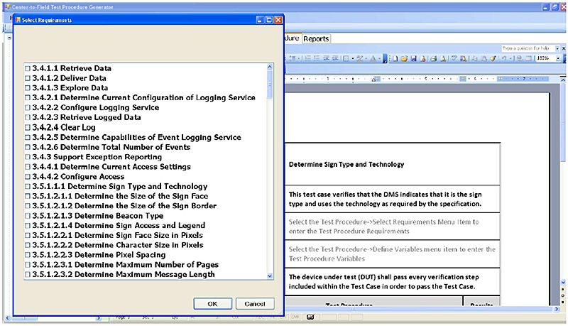
(Extended Text Description: Author's relevant description: Screenshot of the TPG GUI is shown with a popup screen "Select Requirements" banner. Popup shows one box depicting the requirements contained in that standard. Below right are OK and "Cancel" buttons arranged horizontally. Again, we do not describe the Requirements text shown, only that the box displays Requirements that occur during the execution of that command "Continuation of Select the Requirements" screenshot is shown taken with permission from Center-to-Field Test Procedure Generator User Manual, v2.0, FHWA, July 15, 2015.)
Source: Center-to-Field Test Procedure Generator User Manual, v2.0, FHWA, July 15, 2015
Slide 40:
Learning Objective #6
Example Test Procedure for a DMS (cont.)
Select the Requirements
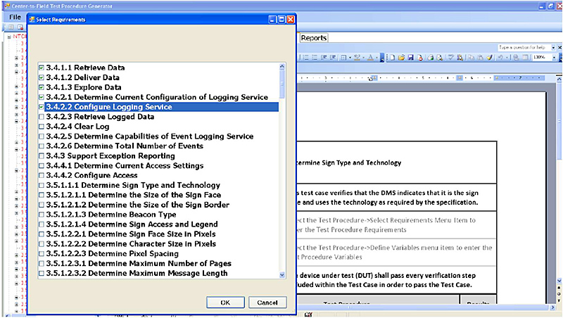
(Extended Text Description: Author's relevant description: Identical to previous slide, but with "3.4.2.2 Configure Logging Service" selected in blue. "Further continuation of Select the Requirements" screenshot is shown taken with permission from Center-to-Field Test Procedure Generator User Manual, v2.0, FHWA, July 15, 2015.)
Source: Center-to-Field Test Procedure Generator User Manual, v2.0, FHWA, July 15, 2015
Slide 41:
Learning Objective #6
Example Test Procedure for a DMS (cont.)
Populated Test Procedure Document
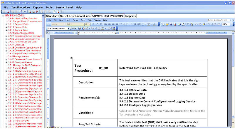
(Extended Text Description: Author's relevant description: Screenshot of the TPG GUI with the embedded MS Word document table filled out in entirety except the "Variable(s) entry remains grayed out. "Populated Test Procedure Document" screenshot is shown taken with permission from Center-to-Field Test Procedure Generator User Manual, v2.0, FHWA, July 15, 2015.)
Source: Center-to-Field Test Procedure Generator User Manual, v2.0, FHWA, July 15, 2015
Slide 42:
Learning Objective #6
Example Test Procedure for a DMS (cont.)
Define Variables
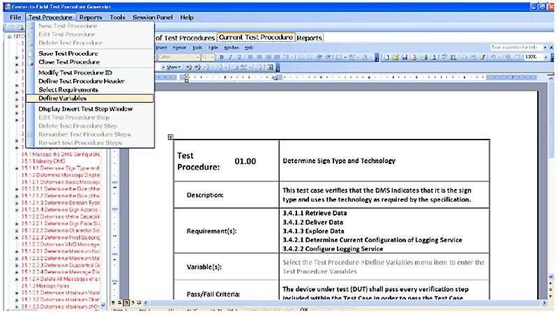
(Extended Text Description: Author's relevant description: Identical to slide 41, but with "Define Variables" selected in blue. "Define Variables" screenshot is shown taken with permission from Center-to-Field Test Procedure Generator User Manual, v2.0, FHWA, July 15, 2015.)
Source: Center-to-Field Test Procedure Generator User Manual, v2.0, FHWA, July 15, 2015
Slide 43:
Learning Objective #6
Example Test Procedure for a DMS (cont.)
Define Variables
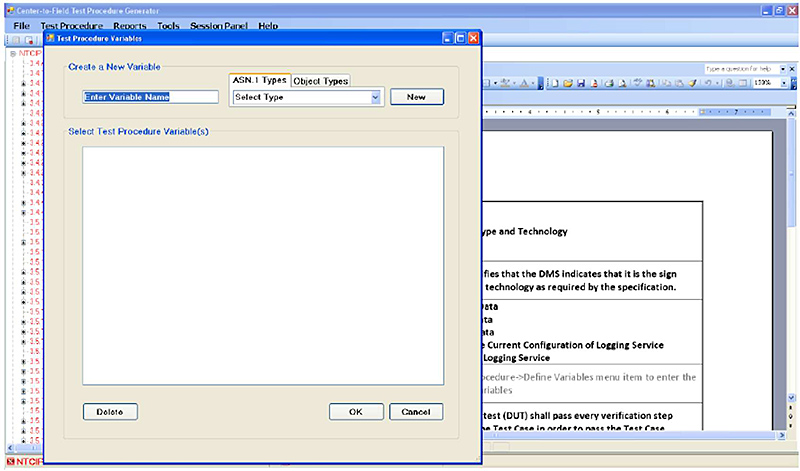
(Extended Text Description: Author's relevant description: Screenshot of the TPG GUI is shown with a popup screen "Select Variable Name". Below are "Delete", OK and "Cancel" buttons arranged horizontally at the bottom of the GUI. Below the banner "Create a New Variable" text entry box is provided. To the right, "ASN.1 Types" and "Object Types" selection tabs are provided with a "Select Type" pull down button provided for those selections. "Continuation of Define Variables" screenshot is shown taken with permission from Center-to-Field Test Procedure Generator User Manual, v2.0, FHWA, July 15, 2015.)
Source: Center-to-Field Test Procedure Generator User Manual, v2.0, FHWA, July 15, 2015
Slide 44:
Learning Objective #6
Example Test Procedure for a DMS (cont.)
Define Variables
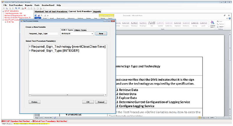
(Extended Text Description: Author's relevant description: Screenshot of the TPG GUI is shown with a popup screen "Test Procedure Variables" Pop identical to the previous slide along with the same text entry boxes. Popup shows one box depicting the "Test Procedure Variables" contained in that standard. Below are "Delete", "OK" and "Cancel" buttons arranged horizontally at the bottom. Above. "Further continuation of Define Variables" screenshot is shown taken with permission from Center-to-Field Test Procedure Generator User Manual, v2.0, FHWA, July 15, 2015.)
Source: Center-to-Field Test Procedure Generator User Manual, v2.0, FHWA, July 15, 2015
Slide 45:
Learning Objective #6
Example Test Procedure for a DMS (cont.)
Define Variables
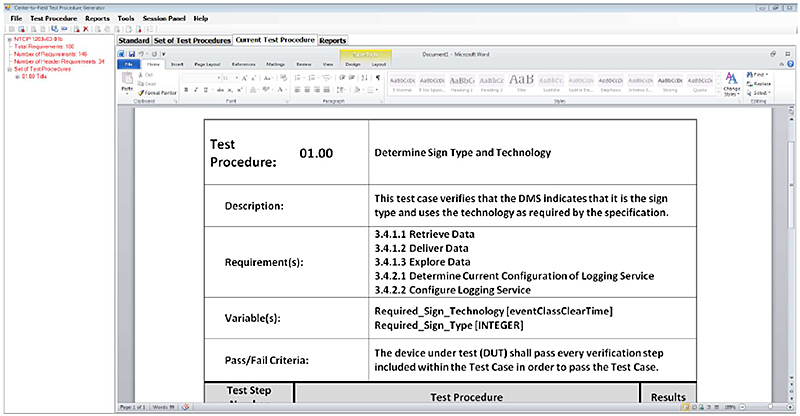
(Extended Text Description: Author's relevant description: Screenshot of the TPG GUI with the embedded MS Word document table filled out in entirety and without grayed out text. "Further continuation of Define Variables" screenshot is shown taken with permission from Center-to-Field Test Procedure Generator User Manual, v2.0, FHWA, July 15, 2015.)
Source: Center-to-Field Test Procedure Generator User Manual, v2.0, FHWA, July 15, 2015
Slide 46:
Learning Objective #6
Example Test Procedure for a DMS (cont.)
Define a Test Procedure Step
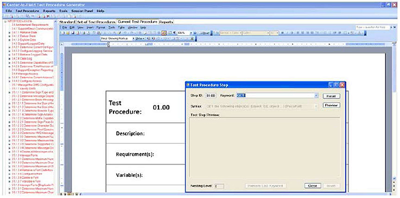
(Extended Text Description: Author's relevant description: Screenshot of the TPG GUI is shown with a popup screen "Test Procedure Step" Pop up shows "Step ID" and "Keyword" data entry boxes. Below are and active "Close" button and grayed out "Insert" buttons. "Define a Test Procedure Step" screenshot is shown taken with permission from Center-to-Field Test Procedure Generator User Manual, v2.0, FHWA, July 15, 2015.)
Source: Center-to-Field Test Procedure Generator User Manual, v2.0, FHWA, July 15, 2015
Slide 47:
Learning Objective #6
Example Test Procedure for a DMS (cont.)
Select the Objects for the Test Step

(Extended Text Description: Author's relevant description: Screenshot of the TPG GUI is shown with a popup screen "Select One or More Objects" Pop up shows two data selection boxes. The box to the left depicts the objects to be selected. Those selections are dragged and dropped into the box to the right. Below are OK and "Cancel" buttons below the left area and "Add to Keyword List" and "Remove from Keyword List" buttons below the right area. Again, we do not describe the text entries shown, only that the boxes are used to select objects. "Select the Objects for a Test Step" screenshot is shown taken with permission from Center-to-Field Test Procedure Generator User Manual, v2.0, FHWA, July 15, 2015.)
Source: Center-to-Field Test Procedure Generator User Manual, v2.0, FHWA, July 15, 2015
Slide 48:
Learning Objective #6
Example Test Procedure for a DMS (cont.)
Inserting a Test Procedure Step
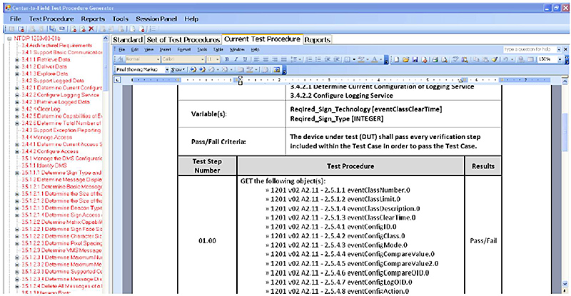
(Extended Text Description: Author's relevant description: Screenshot of the TPG GUI with the embedded MS Word document table filled out in entirety including Test Step Number, Test Procedure list and Results columns. Again, we do not describe the text shown, only how the boxes are used. "Inserting a Test Procedure Step" screenshot is shown taken with permission from Center-to-Field Test Procedure Generator User Manual, v2.0, FHWA, July 15, 2015.)
Source: Center-to-Field Test Procedure Generator User Manual, v2.0, FHWA, July 15, 2015
Slide 49:
Learning Objective #6
Example Test Procedure for a DMS (cont.)
Saving the Test Procedure

(Extended Text Description: Author's relevant description: Screenshot identical to previous slide, but with "Test Procedure" pulled down with "Save Test Procedure" selected in blue. "Saving a Test Procedure" screenshot is shown taken with permission from Center-to-Field Test Procedure Generator User Manual, v2.0, FHWA, July 15, 2015.)
Source: Center-to-Field Test Procedure Generator User Manual, v2.0, FHWA, July 15, 2015
Slide 50:
Learning Objective #6
Example Test Procedure for a DMS (cont.)
Closing the Test Procedure
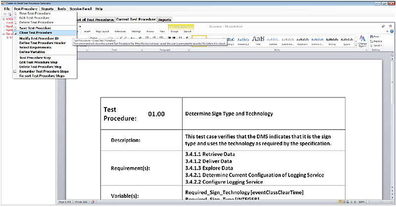
(Extended Text Description: Author's relevant description: Screenshot identical to previous slide but with "Close Test Procedure" selected in blue. "Closing the Test Procedure" screenshot is shown taken with permission from Center-to-Field Test Procedure Generator User Manual, v2.0, FHWA, July 15, 2015.)
Source: Center-to-Field Test Procedure Generator User Manual, v2.0, FHWA, July 15, 2015
Slide 51:
Learning Objective #6
Example Test Procedure for a DMS (cont.)
Saving the Sets of Test Procedure
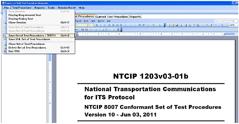
(Extended Text Description: Author's relevant description: Screenshot of TPG GUI with "File" pulled down with "Save Set of Test Procedures / TPRTM" selected in yellow. "Saving the Sets of Test Procedure" screenshot is shown taken with permission from Center-to-Field Test Procedure Generator User Manual, v2.0, FHWA, July 15, 2015.)
Slide 52:
Learning Objective #6
Example Test Procedure for a DMS (cont.)
Saving the Sets of Test Procedure
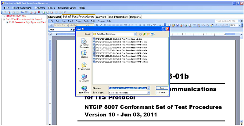
(Extended Text Description: Author's relevant description: Screenshot of the TPG GUI is shown with a popup screen "Save As" banner. Popup shows a selection of "Save In" files for selection. Below are "Save" and "Cancel" buttons. Arranged vertically in the lower right corner. "File Name" and "Save as Type" text entry boxes are shown, arranged vertically in the lower left corner. "Continuation of Saving the Sets of Test Procedure" screenshot is shown taken with permission from Center-to-Field Test Procedure Generator User Manual, v2.0, FHWA, July 15, 2015.)
Slide 53:
Learning Objective #6
Example Test Procedure for a DMS (cont.)
Saving XML Test Procedure
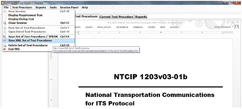
(Extended Text Description: Author's relevant description: Screenshot of TPG GUI with "File" pulled down, and with "Save XML Set of Test Procedures / TPRTM" selected in blue. "Saving XML Test Procedure" screenshot is shown taken with permission from Center-to-Field Test Procedure Generator User Manual, v2.0, FHWA, July 15, 2015.)
Source: Center-to-Field Test Procedure Generator User Manual, v2.0, FHWA, July 15, 2015
Slide 54:
Learning Objective #6
Example Test Procedure for a DMS (cont.)
Displaying XML Test Procedure
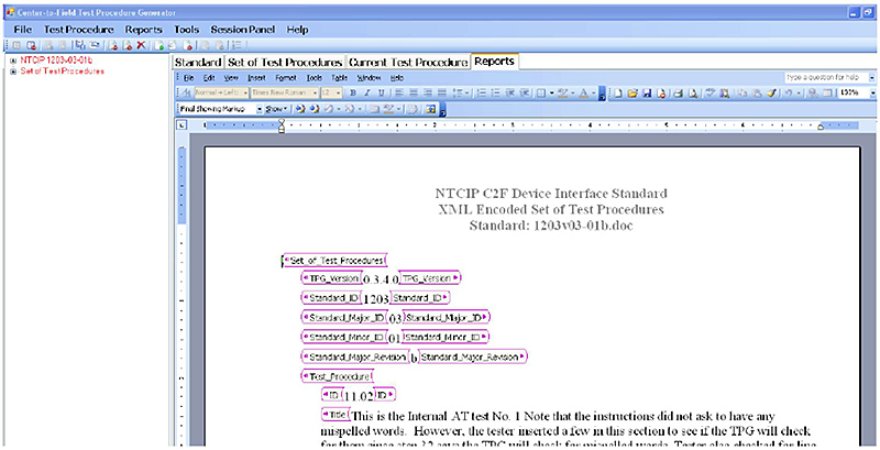
(Extended Text Description: Author's relevant description: Screenshot of the TPG GUI with the embedded MS Word document depicting the set of Test Procedures in XML format. Again, we do not describe the XML shown, only that the box displays XML outputs that occur during the execution of that command "Displaying XML Test Procedure" screenshot is shown taken with permission from Center-to-Field Test Procedure Generator User Manual, v2.0, FHWA, July 15, 2015.)
Source: Center-to-Field Test Procedure Generator User Manual, v2.0, FHWA, July 15, 2015
Slide 55:

Slide 56:
Learning Objective #6
Which is the order of the TPG example workflow?
Answer Choices
- XML Requirement Step Object Variable
- Object Variable Requirement Step XML
- Requirement Variable Step Object XML
- Object Requirement Variable Step XML
Slide 57:
Learning Objective #6
Review of Answers
 a) XML Requirement Step Object Variable
Incorrect. XML is an output created at end of workflow.
 b) Object variable Requirement Step XML
Incorrect. Objects are not known until Requirements are known.
 c) Requirement Variable Step Object XML
Correct! Requirements are populated with Variables that are tested in Steps of Objects that create XML output.
 d) Object Requirement Variable Step XML
Incorrect. Objects are not known until Requirements are known and Test Steps must be known before Objects are selected.
Slide 58:
Summary of Learning Objective #6
Use the TPG to Generate Test Procedures for a Variety of Equipment
- TPG follows NTCIP 8002 for uniform numbering system and content
- Role of TPG includes proper use of key words, test procedure in IEEE 829 format, and XML outputs for use by test equipment
- We stepped through a successful TPG installation
- We used the TPG to develop an example test procedure for an NTCIP 1203 v03 dynamic message sign
Slide 59:
Learning Objective #7: Adapt the Generated Test Procedures to Procurement Contract Terms and Conditions for Successful Project Conclusion
- Discuss lessons learned from unsuccessful ITS projects and explain how to avoid repetition
- BEGIN by planning a test procedure to be used successfully at the END of the procurement
- Demonstrate how to include clear, unambiguous contract terms and conditions
- Demonstrate how to work backwards FROM the project's successful end TO the beginning of the procurement process
Slide 60:
Learning Objective #7
Plan the Test Procedure from the Beginning
BEGIN by Planning As If You Were at the END
- DO NOT approach an ITS project as a normal construction project
-
DO approach the beginning of an ITS project as if ending an IT project
- Cost to correct at the end is 100X more expensive than the cost to correct at the point where the defect is created
- Begin at the end
-
In the beginning, the contract should provide the ending:
- Test case inputs
- Test procedures, the TPG variables
- Expected TPG outputs
- Manufacturers can use the TPG for testing throughout the project
- Eliminates the unexpected results that are expensive to fix later
Slide 61:
Learning Objective #7
Plan the Test Procedure from the Beginning
Plan the Level Tests As If the Project Is Ending
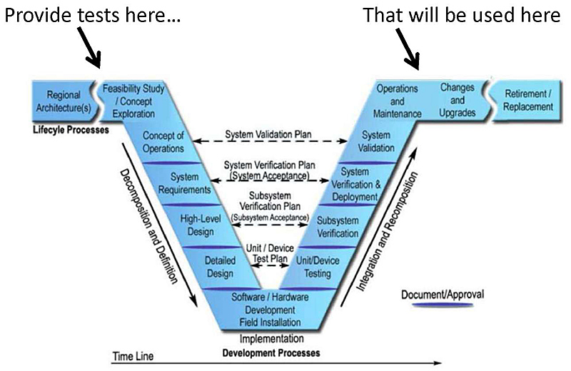
(Extended Text Description: Graphic depicts the USDOT Systems Engineering Process (SEP) VEE model. The left-hand side of the VEE depicts six blue boxes, descending towards the lower right with a downward arrow labeled "Decomposition and Definition". The box and the bottom valley of the VEE is labeled "Implementation" below. The boxes are labeled "Regional Architecture", "Feasibility Study / Concept Exploration", "Concept of Operations", "System Requirements", "High Level Design" and "Detailed Design", arranged from upper right to lower left to the bottom of the VEE. The right-hand side of the VEE depicts seven boxes ascending towards the upper right labeled "Integration and Recomposition with an arrow directed upwards. The boxes are labeled "Unit / Device Testing", "Subsystem Verification", "System Verification and Deployment" "System Validation", "Operations and Maintenance", "Changes and Upgrades" and "Retirement / Replacement". Connecting the left and right sides of the VEE and at the bottom of the VEE is one box labeled "Software / Hardware Development Field Installation". "VEE workflow" graphic is shown taken with permission from Systems Engineering for Intelligent Transportation Systems, USDOT, January 2007.)
Source: Systems Engineering for Intelligent Transportation Systems, USDOT, January 2007
Slide 62:
Learning Objective #7
Lessons Learned from Unsuccessful ITS Projects
From T204 Part 1, Learning Objective #3
-
The odds are slim that ITS projects will be successful:
- On time
- Within budget
- Include all of the agreed features
-
Roads projects are designed by consultants and built by contractors
- Does not work well for ITS projects
- ITS has large IT content
Slide 63:
Learning Objective #7
How to Avoid Repetition of Failure
Find and Correct Defects Early in the Project
-
Projects should require level testing at:
- Unit / device level
- Subsystem level
- System integration level
- System validation level
- Deployment and operation level (commissioning)
-
Each step of the system design has a test for that level
- Test procedure
- Expected outcomes
Slide 64:
Learning Objective #7
How to Avoid Repetition of Failure (cont.)
Find and Correct Defects Early in the Project
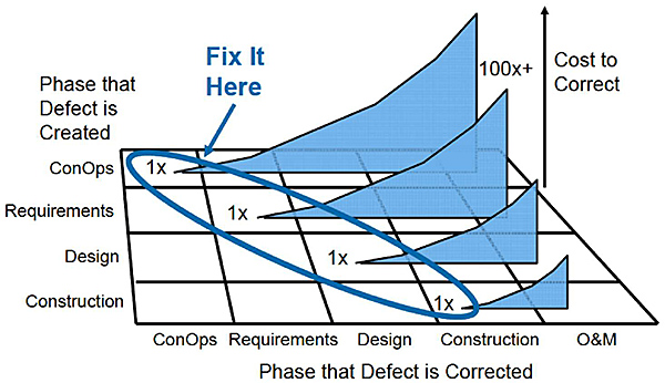
(Extended Text Description: Graphic depicts a grid of five horizontal lines and six vertical lines as a three dimensional graph. The vertical axis is labeled "Phase the Defect is Created", "ConOps", "Requirements", "Design" and "Construction" from top to bottom and located to the left of the first vertical line. The horizontal axis is labeled "ConOps", "Requirements", "Design", "Construction" and "O&M" from left to right and located below the lower horizontal line. Four perpendicular blue triangular planes are located within each horizontal space between the five horizontal grid lines. Each plane extends in decreasing height from the upper plane to the lower plane. A blue oval encircles the left-most tip of the four planes that is labeled "Fix It Here". A black arrow directed vertically is located to the right of the grid labeled "Cost to Correct". "Phase the Defect is Corrected" graphic is shown taken with permission from Systems Engineering for Intelligent Transportation Systems, USDOT, January 2007.)
Source: Systems Engineering for Intelligent Transportation Systems, USDOT, January 2007
Slide 65:
Learning Objective #7
Use Clear and Unambiguous Contract Terms
Contract Provisions Should Provide:
- Varieties of equipment needed
- Standards for each variety
- Conformance Group (CG) within each standard
- Test cases for each CG
- The expected test outputs
Slide 66:
Learning Objective #7
Use Clear and Unambiguous Contract Terms (cont.)
Contract Requirements
-
Contracts should require:
- The use of TPG
- Use of IEEE 829 format for records
- Present Test Outputs in XML format
- Use of standardized objects
- Use Block object formats and dialogs
- Use ONLY XML format for Manufacturer Specific Object (MSO) and dialogs for special needs
Slide 67:
Learning Objective #7
Use Clear and Unambiguous Contract Terms (cont.)
Contract Prohibitions
-
Contracts should prohibit:
- MSOs in place of standardized conformance groups
- MSOs that are not documented for interoperability
Slide 68:

Slide 69:
Learning Objective #7
ITS project cost and schedule should be developed in which of the following orders?
Answer Choices
- From the test procedures back through the project workflow
- From the requirements only
- To enforce the contract terms at the end of the project
- To minimize the planning costs up front
Slide 70:
Learning Objective #7
Review of Answers
 a) From the test procedures back through the project workflow
Correct! Providing the test procedures in the contract terms allows the manufacturers to use the TPG throughout the design phase to eliminate defects early.
 b) From requirements only
Incorrect. Providing only the requirements allows multiple interpretations that will be costly to correct at installation.
 c) To enforce contract terms at the end of the project
Incorrect. Contract terms should enforce continuous verification throughout the project, not enforcement at the end.
 d) To minimize planning costs up front
Incorrect. Additional up-front planning reduces overall costs.
Slide 71:
Summary of Learning Objective #7
Adapt the Generated Test Procedures to Procurement Contract Terms and Conditions for Successful Project Conclusion
- Lesson learned from successful ITS projects: Testing insures success
- Plan the test procedure used at project end in the beginning
- Clear, unambiguous contract terms include test procedures with expected results and ban the use of poor design practices
- A good procurement process documents the successful project end, then works backwards through the procurement process to the contract terms
Slide 72:
Learning Objective #8: Develop Complex Test Procedures That Pull Together NTCIP Elements Using the TPG
- Analyze pre-existing central station from Vendor A
- Plan upcoming procurement contract to add variety of equipment
- Specify, create, and test MSOs for special needs
- Use of TPG as acceptance test throughout the project
- Explain how terms and conditions are based on the test procedure
- Use TPG outputs as pass/fail criteria for project end and example of reports for project end
Slide 73:
Learning Objective #8
Analyze Pre-Existing Central Station from Vendor A
Requirements Currently Supported
- Identify requirements currently supported
- Identify new requirements (if any)
- Those objects associated with the selected requirements will automatically show up as part of the TPG operations
- Requirements "left over" from TPG operations might require a manufacturer-specific design to realize the requirements
- Determine existing communications media and performance
Slide 74:
Learning Objective #8
Plan Upcoming Procurement Contract to Add Variety of Equipment
Add Equipment and Identify the Gap:
- Dynamic message signs
- Additional actuated signal controllers
- Adaptive control equipment
- Identify the gap of additional functionality to meet requirements
Slide 75:
Learning Objective #8
Specify, Create, and Test MSOs for Special Needs
Special Needs Might Include:
- Control of normal traffic flow based on known vehicle counts
- Control of abnormal traffic flow from nearby events center
- Automatic adaptation of signal timing to abnormal traffic flow
- Update of signal timing every three seconds
- Elimination of the need for manual control of traffic by police
Slide 76:
Learning Objective #8
Use of TPG As Acceptance Test Throughout the Project
Use the TPG to Guide Each Level Test
- Create test procedure header
- Select requirement to fulfill user needs
- Define the variables
- Define the steps of the test procedure
- Select objects
- Create XML outputs
Slide 77:
Learning Objective #8
Explain How Terms and Conditions Are Based on the Test Procedure
Include Test Procedure and Expected Results
- Include the test procedure for each level of the system in the contract
- Include the expected outputs from the TPG in the contract terms
- Remaining requirement, such as Adaptive, become MSOs
- Include MSO documentation in contract for interoperability
- Require test reports at each level before proceeding to the next level
Slide 78:
Learning Objective #8
Use TPG Outputs As Pass/Fail Criteria for Project End and Example of Reports for Project End
Compare TPG XML Outputs to Expected XML Outputs
- The expected outputs of each level test are known in the beginning
- The TPG produces script files (in an XML format) for use by test equipment.
- Differences between the expected TPG outputs and the level test procedure outputs are not "failures" but rather anomalies
- Each anomaly report is addressed and disposed by the stakeholders
Slide 79:
Learning Objective #8
NTCIP 8007
Relationship between NTCIP 8007 and IEEE 829
- NTCIP 8007 sets the format for all testing documentation including Test Procedures
- TPG uses the 8007 format that was modified to meet the requirements of 829
Slide 80:
Learning Objective #8
Standards Supported by TPG
TPG Supports NTCIP 12XX Standards with SE Content
- NTCIP 1203 v03 Dynamic Message Signs
- NTCIP 1204 v03 Environmental Sensor Station Interface
- NTCIP 1209 v02 Data Element Definitions, Transportation Sensors
- NTCIP 1210 v01 Field Management Station, Part 1
- NTCIP 1211 v02 Objects for Signal Control and Prioritization
- NTCIP 1213 v02.20 Object Definition, Electrical Management Systems
Slide 81:
Learning Objective #8
TPG Distribution
Copies of the TPG can be obtained:
- Kingsley Azubike, USDOT, Kingsley.Azubike@dot.gov
- https://www.standards.its.dot.gov/DeploymentResources/Tools
Slide 82:
What We Have Learned
- NTCIP 8002 will define uniform numbering and content for NTCIP 12XX series center-to-field standards.
- Using TPG to enter inputs insures the proper use of key words and creates test procedures in IEEE 829 steps.
- TPG outputs in XML_format provides test documentation and can be used as inputs to automated test equipment.
- Begin by planning test procedures to be used at the end.
- Contracts should provide test procedures and expected outputs in order to verify requirements throughout the entire project.
- Contract should require objects and dialogs for special needs.
- Contracts ban poor practice of undocumented MSOs for interoperability.
Slide 83:
Resources
- T204 Part 1 of 2: How to Develop Test Procedures for an ITS Standards-Based Test Plan, Part 1 of 2
- Student Supplement: T204 Part 2 of 2: How to Develop Test Procedures for an ITS Standards-Based Test Plan, Part 2 of 2
- IEEE 829: IEEE Standard for Software and System Test Documentation http://standards.ieee.org/findstds/standard/829-2008.html
- NTCIP 1204 v03 DMS, www.ntcip.org
- PCB Website: Module T201, T202 Available stds training.aspx
- Systems Engineering for Intelligent Transportation Systems, USDOT, January 2007 http://ops.fhwa.dot.gov/publications/seitsguide/seguide.pdf
- Center to Field Test Procedure Generator User Manual, v2.0, Federal Highway Administration, July 15, 2015
- TPG User Manual: Contact Kingsley Azubike, FHWA at https://www.standards.its.dot.gov/DeploymentResources/tools
Slide 84:
