Module 58 - T307
T307: Applying Your Test Plan to the Advanced Transportation Controller Based on ATC 5201 Standard v06
HTML of the PowerPoint Presentation
(Note: This document has been converted from a PowerPoint presentation to 508-compliant HTML. The formatting has been adjusted for 508 compliance, but all the original text content is included, plus additional text descriptions for the images, photos and/or diagrams have been provided below.)
Slide 1:
(Extended Text Description: Welcome - Graphic image of introductory slide. A large dark blue rectangle with a wide, light grid pattern at the top half and bands of dark and lighter blue bands below. There is a white square ITS logo box with words "Standards ITS Training - Transit" in green and blue on the middle left side. The word "Welcome" in white is to the right of the logo. Under the logo box is the logo for the U.S. Department of Transportation, Office of the Assistant Secretary for Research and Technology.)
Slide 2:
(Extended Text Description: This slide, entitled "Welcome" has a photo of Ken Leonard, Director, ITS Joint Program Office, on the left hand side, with his email address, Ken.Leonard@dot.gov. A screen capture snapshot of the home webpage is found on the right hand side - for illustration only - from August 2014. Below this image is a link to the current website: www.its.dot.gov/pcb - this screen capture snapshot shows an example from the Office of the Assistant Secretary for Research and Development - Intelligent Transportation Systems Joint Program Office - ITS Professional Capacity Building Program/Advanced ITS Education. Below the main site banner, it shows the main navigation menu with the following items: About, ITS Training, Knowledge Exchange, Technology Transfer, ITS in Academics, and Media Library. Below the main navigation menu, the page shows various content of the website, including a graphic image of professionals seated in a room during a training program. A text overlay has the text Welcome to ITS Professional Capacity Building. Additional content on the page includes a box entitled What's New and a section labeled Free Training. Again, this image serves for illustration only. The current website link is: https://www.its.dot.gov/pcb.)
Slide 3:
T307:
Applying Your Test Plan to the Advanced Transportation Controller Based on ATC 5201 Standard v06
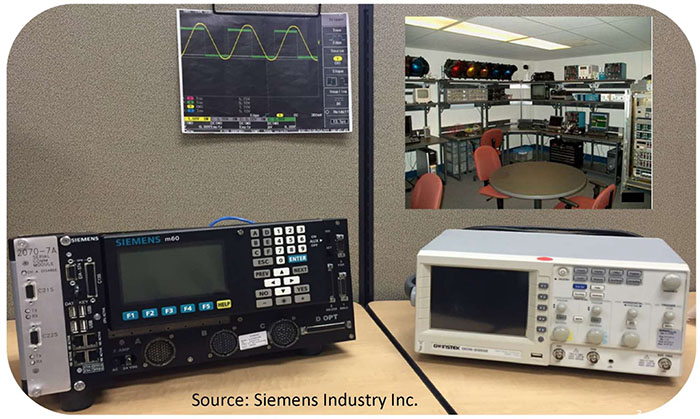
(Extended Text Description: Author's relevant description: Title slide, entitled T307 Applying Your Test Plan to the Advanced Transportation Controller Based on ATC5201 Standard v06. A photo below the title depicts and ATC 5201 standard controller on the left and a test instrument on the right.)
Slide 4:
Instructor

Dave Miller
Principal Systems Engineer
Siemens Industry, Inc.
RC-US MO MM-ITS S OPS
Austin, Texas, USA
Slide 5:
Learning Objectives
- Identify key elements of ATC 5201 Standard equipment for testing documentation
- Describe within the context of a systems engineering lifecycle the role of a test plan and the testing to be undertaken
- Describe the application of good testing documentation for transportation controller equipment based on the ATC 5201 v06 Standard
- Describe the testing of ATC using sample testing documentation
Slide 6:
Learning Objective 1
- Identify key elements of ATC 5201 Standard Equipment for Testing Documentation
Slide 7:
Key Elements of ATC 5201 Standard v06
What Is the Purpose of This Module?
This module teaches user agencies how to create ATC Testing documentation based on:

(Extended Text Description: This slide contains a graphic to the right depicting one page of a Test Document. The left is the following bulleted text:
- ATC 5201 v06 Standard requirements
- Agency ATC procurement configuration
- IEEE 829-2008 formats
)
Slide 8:
Key Elements of ATC 5201 Standard v06
Why Do We Need ATC Testing Documentation?
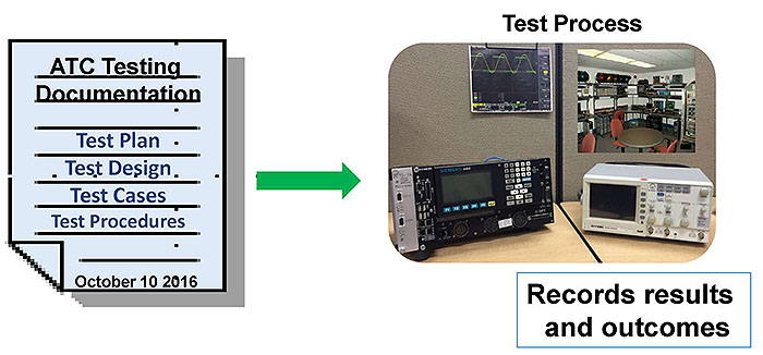
Guides us in conducting the test process to establish conformance to the standard, compliance to agency ATC configuration, and compatibility among concerned objects-modules of ATC.
Slide 9:
Key Elements of ATC 5201 Standard v06
What Is Advanced Traffic Controller (ATC)?
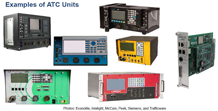
ATC is a general purpose field-computing platform for transportation applications (Hardware/Software)
See Modules A307a and A307b for details
Slide 10:
Key Elements of ATC 5201 Standard v06
How Is ATC Used?
-
ATC 5201 standard applies to multiple transportation applications:
- Traffic Signal Control/Traffic Management
- Transit/Light Rail Priority
- Emergency Management
- Lane Use
- Red Light Enforcement
- Speed Monitoring/Enforcement
- Access Control
- Advanced Traveler Information Systems (ATIS)
- Data Collection Systems
- Connected Vehicle (CV) Applications
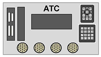
ATC testing will be affected by applications running on the ATC Units
Slide 11:
What Needs to Be Tested
What Is Included in the Standard: ATC Major Objects and Interfaces
-
A large number of objects (approx. 73) are included in the standard from which an agency creates a procurement configuration:
- Mandatory (Core) Objects are always included in procurement
- Optional Objects are selected as per user needs
-
Testing Documentation includes what is being purchased by an agency (Mandatory + Optional)
- We will call it a Procurement Configuration

Slide 12:
What Needs to Be Tested
What Is Included in the Standard: Environmental Conditions
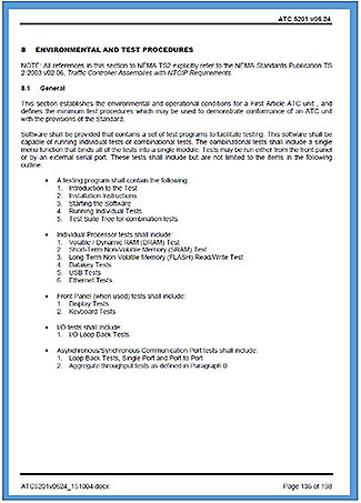
ATC 5201 Standard, Section 8:
- 1st Article conformance/qualification
- Minimum list of test procedures
- Normative references to NEMA TS2
- Useful for Master Test Plan (MTP)
-
Can be conducted by:
- End user agency laboratory
- Independent laboratory

Slide 13:
What Needs to Be Tested
What Is NOT Included in the ATC 5201 v06 Standard
- Applications Programming Interface (API) is NOT included (See Modules A308a and A308b and upcoming Module T308)
- Signal Control software is NOT covered by this standard
-
This standard is NOT SEP-based, hence User Needs and Requirements are NOT available for testing documentation
(see A307a and A307b Understanding User Needs/Requirements)

Slide 14:
What Needs to Be Tested
Diagnostic Acceptance Test (DAT)
- 1. DAT is performed on the first article ATC unit and is part of the preproduction or pre-deployment process
- DAT not typically performed on all units deployed
- Production Testing is performed on all units deployed
- ATC 5201 DAT: Environmental and Operating section
- Manufacturers typically use automated self-test DAT
- Agencies typically use automated self-test DAT

8.5.2 Transients, Power Service (DAT)
The ATC unit under test shall meet all requirements as defined in NEMA TS2, Section 2.1.6, Transients, Power Service.
8.5.3 Nondestructive Transient Immunity (DAT)
The ATC unit under test shall meet all requirements as defined in NEMA TS2, Section 2.1.8, Nondestructive Transient Immunity, with the following variations:
- Test voltage amplitude shall be 2000 ± 100 V, both positive and negative polarity.
Slide 15:
What Needs to Be Tested
Suggested Approach to Preparing Testing Documentation
- Consult Module A307b for guidance on identifying Mandatory and Optional objects and related requirements
-
Identify essential areas that must be addressed for conformance to the standard:
- Operational Voltages
- I/O Requirements
- User Interface Requirements
- CPU Performance and Memory Requirement
- Other Requirements
- Consider Cabinet Standards influence
- Assess Agency Procurement Configuration

(Extended Text Description: This slide contains a graphic to the right depicting one page of a Test Document with the text Mandatory objects are ALWAYS included in all procurement Configuration to the left with an arrow pointing to the Test Document.)
Slide 16:
What Needs to Be Tested
Review of Mandatory (Core) + Optional Objects
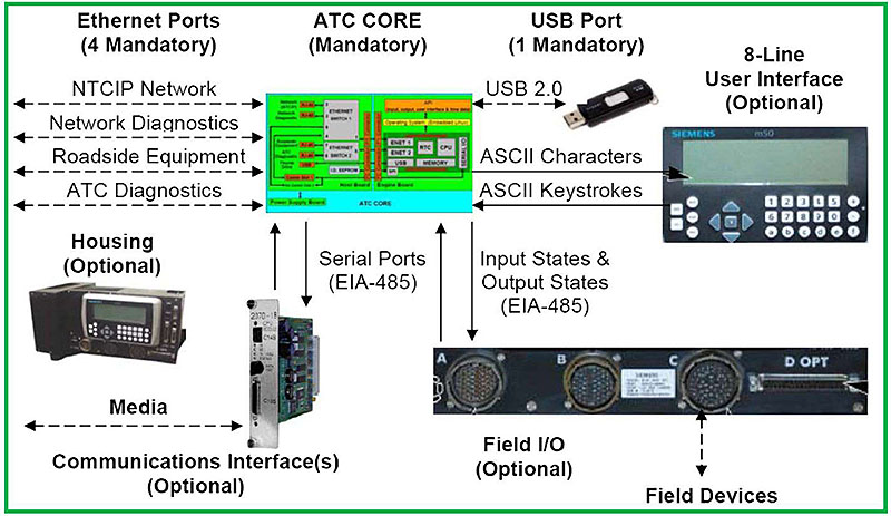
(Extended Text Description: Author's relevant description: This slide has a graphic of an engine board with dashed lines to graphics of Housing, Field I/O, Communications, User Interface and a memory device. Key Message: In addition to the mandatory Core objects that are included in every ATC configuration, the ATC standard also describes optional objects that may or may not be included in the procured ATC configuration. Therefore, each ATC test plan begins with identifying the objects to be tested. In this LO, the end user must learn that Step 1 in the testing process is identifying the major objects-modules and the power budget so that the test plan only tests what is being purchased. In this slide, the Need for TS2 cabinet compatibility is met by the Requirement for a mandatory TS2 power supply calibration and an optional FIO with NEMA ABC connectors.)
Slide 17:
What Needs to Be Tested
Mandatory Hardware Objects:
Engine Board, Memory, and Operating System (OS)
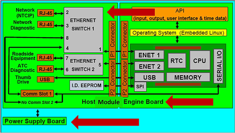
(Extended Text Description: Author's relevant description: This slide has a graphic of Engine Board and Host Module. Key Message: This slide depicts the mandatory hardware objects that are always included in any ATC configuration and therefore always need to be included in all ATC test plans. Mandatory hardware objects always require testing, shown as ATC Core in the graphic: Engine Board, Power Supply, Host Module.)
Slide 18:
What Needs to Be Tested
Mandatory Engine Board Requirements Must be Tested
- Microprocessor
- Two Ethernet Ports
- Real Time Clock
- Memory
- Serial Inputs/Outputs
- Serial Peripheral Interface
- Standardized Connectors

(Extended Text Description: Author's relevant description: This slide has a graphic of the Engine Board on the right. Key Message: Each ATC configuration includes a mandatory Engine Board that requires testing.)
Slide 19:
What Needs to Be Tested
Mandatory Engine Board
- Microprocessor

(Extended Text Description: Author's relevant description: This slide is identical to 18 with a red arrow added pointing to CPU. The Central Processor Unit is the microprocessor that executes the software, including operating system and applications such as signal control and ramp meter. The microprocessor is the most likely device to become obsolete as the technology advances quickly. For example, if the microprocessor becomes obsolete, the Engine Board is interchangeable among vendors for "future-proofing.")
Slide 20:
What Needs to Be Tested
Mandatory Engine Board
- Microprocessor
- Two Ethernet Ports
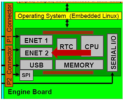
(Extended Text Description: Author's relevant description: This slide is identical to 18 with a red arrow added pointing to ENET2. Key Message: Each ATC configuration includes a mandatory Engine Board that requires testing for: ATC 5201 standard includes two Ethernet ports: Wide area network backhaul connection to central traffic management system, Local area network for roadside equipment, such as Connected Vehicle Roadside Unit.)
Slide 21:
What Needs to Be Tested
Mandatory Engine Board
- Microprocessor
- Two Ethernet Ports
- Real Time Clock

(Extended Text Description: Author's relevant description: This slide is identical to 18 with a red arrow added pointing to RTC - Real time clock maintains time of day and date during power failures.)
Slide 22:
What Needs to Be Tested
Mandatory Engine Board
- Microprocessor
- Two Ethernet Ports
- Real Time Clock
- Memory

(Extended Text Description: Author's relevant description: This slide is identical to 18 with a red arrow added pointing to Memory. Engine Board includes three memory types: Dynamic Random Access Memory used to execute the software, Static Random Access Memory used to hold the controller configuration during power outages, FLASH memory acting as a disk drive for program and data storage.)
Slide 23:
What Needs to Be Tested
Mandatory Engine Board
- Microprocessor
- Two Ethernet Ports
- Real Time Clock
- Memory
- Serial Inputs/Outputs

(Extended Text Description: Author's relevant description: This slide is identical to 18 with a red arrow added pointing to Serial I/O - Serial I/O is used to connect to legacy communications devices, such as phone modems.)
Slide 24:
What Needs to Be Tested
Mandatory Engine Board
- Microprocessor
- Two Ethernet Ports
- Real Time Clock
- Memory
- Serial Inputs/Outputs
- Serial Peripheral Interface

(Extended Text Description: Author's relevant description: This slide is identical to 18 with a red arrow added pointing to SPI - Serial Peripheral Interface used to sense the manufacturer and type of Host Module type, such as NEMA or 332 cabinet interfaces.)
Slide 25:
What Needs to Be Tested
Mandatory Engine Board
- Microprocessor
- Two Ethernet Ports
- Real Time Clock
- Memory
- Serial Inputs/Outputs
- Serial Peripheral Interface
- Standardized Connectors
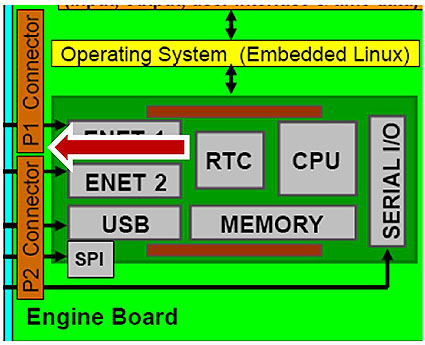
(Extended Text Description: Author's relevant description: This slide is identical to 18 with a red arrow added pointing to P1 connector - Engine Board includes two standardized connectors interchangeable among manufacturers, including pin assignments.)
Slide 26:
What Needs to Be Tested
Mandatory Objects: Host Module
Ethernet Ports/Internet Protocol (IP) Communications

(Extended Text Description: Author's relevant description: This slide has a graphic showing Engine Board, Host Module and Power Supply set on to a blue box labeled "ATC Core". This slide depicts the Host Module-mandatory hardware objects that are always included in any ATC configuration and therefore always need to be included in all ATC test plans.)
Slide 27:
What Needs to Be Tested
Mandatory Host Module Requirements Must Be Tested
- (2) Ethernet Switches
- (4) RJ-45 Ports
- (1) Comm Slot 1
- (1) USB
- ID EEPROM
- Standardized Connectors
- Accepts Engine Board

(Extended Text Description: Author's relevant description: This slide has a graphic showing Engine Board to the right. Key Message: Each ATC requires a mandatory Host Module that accepts the Engine Board. Host Module: (2) Ethernet Switches, (4) RJ-45 Ethernet connectors, EEPROM to identify Host Module, USB connector. Possible Test Cases: Ethernet switch presence and performance, Ethernet ports presence and operation, Proper identification of Host Module.)
Slide 28:
What Needs to Be Tested
Mandatory User Interface Requirements Must Be Tested
Source: Module A307b
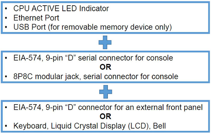
(Extended Text Description: Three blue boxes with bulleted text are stacked on top of each other with the "+" symbol between them. The text is as follows:
- CPU ACTIVE LED Indicator
- Ethernet Port
- USB Port (for removable memory device only)
+
- EIA-574, 9-pin "D" serial connector for console
OR
- 8P8C modular jack, serial connector for console
+
- EIA-574, 9-pin "D" connector for an external front panel
OR
- Keyboard, Liquid Crystal Display (LCD), Bell
)

Slide 29:
What Needs to Be Tested
Mandatory Hardware Objects: Power Supply and Power Fail/Restart Operation
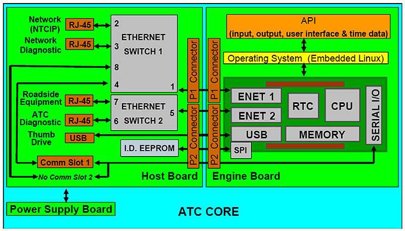
(Extended Text Description: Author's relevant description: This slide has a graphic showing Engine Board, Host Module and Power Supply set on to a blue box labeled "ATC Core". Mandatory hardware objects always require testing, shown as ATC Core in the graphic. Power Supply: ATC always includes a power supply that: Converts service power to low voltage powering the electronic subassemblies, Provides electrical isolation from the service power to eliminate surges and shock hazard, Signals the Engine Board when power is about to fail, Signals the Engine Board when power is restored to begin software execution; Engine Board: ATC always includes an interchangeable Engine Board; Host Module: ATC always includes a Host Module that is not required to be interchangeable among manufacturers or cabinet types.)
Slide 30:
What Needs to Be Tested
Mandatory Power Supply Requirements Must Be Tested
- Converts service voltage to DC
- Time Base
- Power UP signal
- Power DOWN signal
- Power conditioning

Source: Siemens Industry Inc.
Slide 31:
What Needs to Be Tested
Mandatory Operational Voltage Requirements Must Be Tested
5.6.1 Operating Voltage
The transportation controller shall meet the operating voltage requirements per Section 2.1.2 of the NEMA TS 2 Standard.
5.6.2 Operating Frequency
The transportation controller shall meet the operating frequency requirements per Section 2.1.3 of the NEMA TS 2 Standard.
5.6.3 Power Interruptions
The transportation controller shall meet the power interruption requirements per Section 2.1.4 of the NEMA TS 2 Standard.
Source: Module A307b

Slide 32:
What Needs to Be Tested
Optional Objects Examples
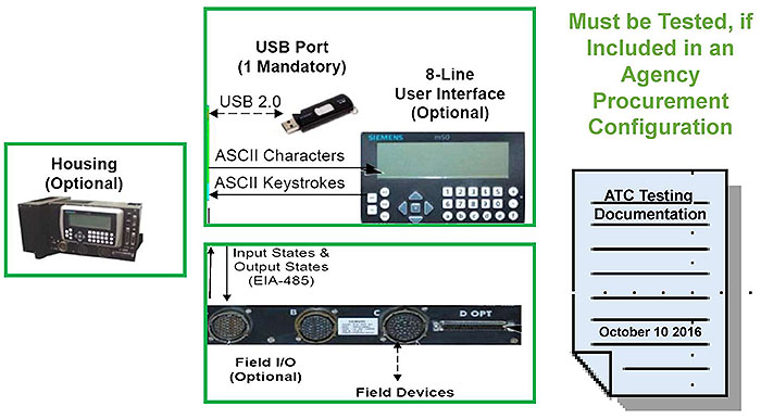
(Extended Text Description: Author's relevant description: This slide has three graphics showing the optional ATC 5201 objects, plus a Testing Document graphic to the right. Key Message: In addition to the mandatory Core objects that are included in every ATC configuration, the ATC standard also describes optional objects that may or may not be included in the procured ATC configuration. Therefore, each ATC test plan begins with identifying the objects to be tested. If an agency procurement configuration includes optional objects, they must be tested. In this Learning Objective, the end user must learn that Step 1 in the testing process is identifying the major objects-modules and the power budget so that the test plan only tests what is being purchased.)
Slide 33:

Slide 34:
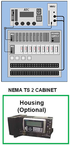
Case Study: NEMA TS 2 Cabinet Compatibility Requirements
NEMA TS 2 Cabinet Compatibility Requirements
- Agency already has a TS 2 cabinet
- Agency needs ATC Installation
- Procurement Configuration requires a NEMA TS 2 cabinet interface
Testing Task:
Check for compatibility in such a configuration
Slide 35:
Case Study: NEMA TS 2 Cabinet Compatibility Requirements
-
Needs require NEMA FIO, Shelf-Mount Housing, Display
- Need for TS2 cabinet compatibility is to be met by the requirement for a mandatory TS2 power supply calibration and an optional FIO with NEMA ABC connectors
How it will be verified
For procurement-testing, a Test Flow must be developed to ensure (verify) that:
- ATC is configured correctly
- Each ATC element is tested
- All ATC objects configured into an ATC will work correctly in a TS2 cabinet

Slide 36:
What Needs to Be Tested
Needs to Requirements Traceability Matrix
See Module A307b
| User Need ID | User Need | FR ID | Functional Requirement | Conformance | Support | Additional Specifications |
|---|---|---|---|---|---|---|
| UN001 | Compliant to ATC 5201 v06 | M | Yes | |||
| FR001 | Configuration shall include Engine Board | M | Yes | Verify to ATC 5201 Engine Board section | ||
| FR002 | Configuration shall include Host Module | M | Yes | Verify to ATC 5201 Host Module section | ||
| FR003 | Configuration shall include Power Supply | M | Yes | Verify to ATC 5201 Power Supply section | ||
| FR008 | Configuration shall include IP communications to TMC | M | Yes | Verify to ATC 5201 network switch section | ||
| Entries can be extended to include Mandatory and Optional FR as per agency procurement configuration | ||||||

Slide 37:
What Needs to Be Tested
Mandatory (Core) Software Objects Must Be Tested
Mandatory Linux OS and Drivers always require testing
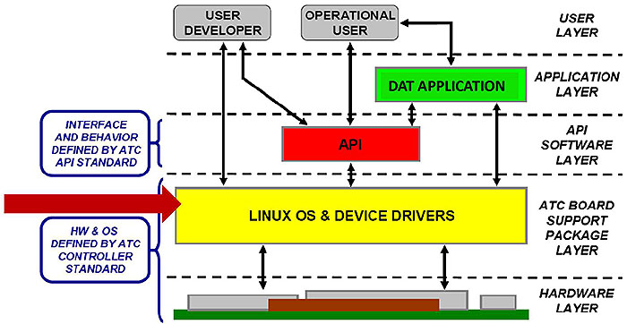
(Extended Text Description: Author's relevant description: This slide has a graphic showing the software layers of the ATC 5201 standard. Key Message: ATC is not a traffic signal controller, but an open-Linux platform that supports applications such as signal control. Mandatory software objects that always require testing: Linux Operating System: Kernel, Drivers, Linux Board Support Package (BSP): Mandatory tool set, Required to compile and load applications; Diagnostic Acceptance Test (DAT) application to self-test the ATC when delivered to the end user: Source code that self-tests ATC, Loop outputs back to inputs for example, Used by 3rd party developers as example, Compile using BSP to produce expected binary code as a Test Case.)
Slide 38:
What Is NOT to Be Tested
Software Objects Not Part of ATC Standard, Not Tested
API & Signal Control software applications are not included

(Extended Text Description: Author's relevant description: This slide has a graphic showing the software layers of the ATC 5201 standard as Slide 38, but with red arrows pointing at DAT application and API.)
Slide 39:
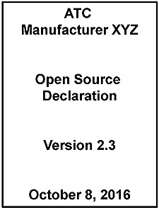
Capture Open Source Linux IP Obligations Within the Contract Terms and Conditions
Open Source Obligations
- Establish clear and unambiguous ownership of IP and derivative works
- https://opensource.org/osd-annotated
- ATC includes an Open Source Linux
OS
Slide 40:
Capture Open Source Linux IP Obligations Within the Contract Terms and Conditions
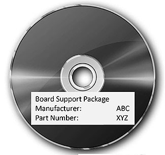
Board Support Package (BSP)
- Library and tools to compile & load 3rd party software for that ATC
- Required by ATC 5201 v06
- No BSP: Not ATC compliant

Slide 41:
Capture Open Source Linux IP Obligations Within the Contract Terms and Conditions
Open Source Terms and Conditions
- Ensure ATC Standard Open Source Linux objects are delivered
- Declaration
- Licenses
- BSP


Slide 42:

Slide 43:
Question
What is NOT an ATC procurement deliverable?
Answer Choices
- Open Source Declaration
- Board Support Package (BSP)
- Application Program Interface (API)
- Open Source Distribution Licenses
Slide 44:
Review of Answers
 a) Open Source Declaration
Incorrect. Open Source Declaration is required in the contract terms to verify ownership and source of software included in ATC by an examination of the Open Source license terms by Legal.
 b) Board Support Package (BSP)
Incorrect. BSP is required as part of the ATC delivery to be compliant to ATC 5201 Standard.
 c) Application Program Interface (API)
Correct! API is controlled by a standard that Is separate from ATC 5201. ATC software can be built using the BSP to run directly on the Linux operating system without the API.
 d) Open Source Distribution Licenses
Incorrect. Open Source software is distributed under license agreements, such as Apache™, verified by license document.
Slide 45:
Learning Objectives
- Identify key objects of ATC 5201 Standard equipment for testing documentation
- Describe within the context of a systems engineering lifecycle the role of a test plan and the testing to be undertaken
Slide 46:
Learning Objective 2
- Describe within the context of a systems lifecycle the role of a test plan and the testing to be undertaken
Slide 47:
Purpose of a Well-Written Documentation Based on IEEE 829-2008
Test Documentation Purpose

(Extended Text Description: This slide shows graphic of the IEEE-829 cover on the right, and the following bulleted text:
-
Test documentation is a general term used to describe unambiguous and common understanding among all stakeholders to:
- Outline what to test (requirements)
- Describe how to test (process)
- IEEE 829-2008 formats are used to prepare documentation
- For whom and why do we need test documentation?
)

Slide 48:
Purpose of a Well-Written Documentation Based on IEEE 829-2008
Test Documentation Purpose (cont.)
Key part of test documentation is ATC Test Plan, which identifies Test Design, Test Case, and Test Procedure documents

(Extended Text Description: Author's relevant description: This slide shows a flow chart of Test Plan to Test Design to Test Case to Test Procedure on the left (Test Plan to Test Design Unit Test to Test Case to Test Procedure), plus a testing document graphic on the right.)
Slide 49:
Structure of a Well-Written Documentation Based on IEEE 829-2008
Test Plan Structure Based on IEEE 829-2008

(Extended Text Description: This slide shows a flow chart of Test Plan to Test Design to Test Case to Test Procedure on the left, plus red arrows pointing at each item with the following text:
Test Plan describes the Overall Approach to Testing
Test Design specifies the details of the test approach; shown here for unit test - similar design exists for Integration Test and Acceptance Test.
Test Case specification outlines a set of test inputs, execution conditions, and expected results.
Test Procedure specification defines the steps to execute a test.
)

Slide 50:
Structure of a Well-Written Documentation Based on IEEE 829-2008
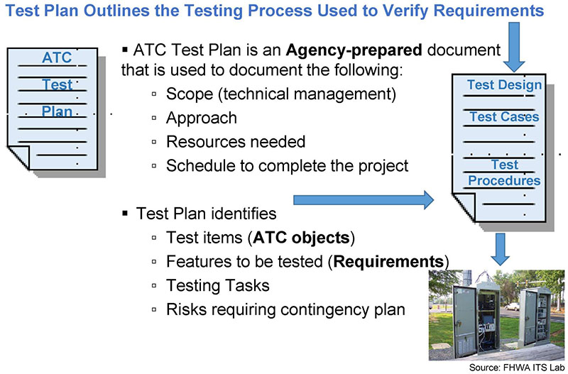
(Extended Text Description: This slide shows a Test Plan graphic on the left, plus a Test Plan to Test Design to Test Case to Test Procedure on the right. A photo of cabinets with open doors is shown in the lower left. In the center is the following text:
-
ATC Test Plan is an Agency-prepared document that is used to document the following:
- Scope (technical management)
- Approach
- Resources needed
- Schedule to complete the project
-
Test Plan identifies
- Test items (ATC objects)
- Features to be tested (Requirements)
- Testing Tasks
- Risks requiring contingency plan
)
Slide 51:
Purpose, Structure, and Content of a Well-Written Documentation Based on IEEE 829-2008
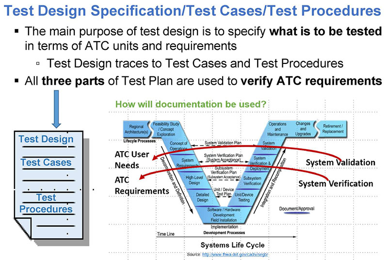
(Extended Text Description: Author's relevant description: This slide shows a Test Plan graphic on the left, plus the VEE model on the right. Key Message: This slide further makes a point that the main purpose of test design is to specify what is to be tested in terms of ATC units and requirements and Test design traces to Test Cases and sometimes to Test Procedures. Additional text at the top is as follows:
Test Design Specification/Test Cases/Test Procedures
-
The main purpose of test design is to specify what is to be tested in terms of ATC units and requirements
- Test Design traces to Test Cases and Test Procedures
- All three parts of Test Plan are used to verify ATC requirements
)
Slide 52:
Purpose, Structure, and Content of a Well-Written Documentation Based on IEEE 829-2008
Documentation for Reporting Test Results/Outcomes
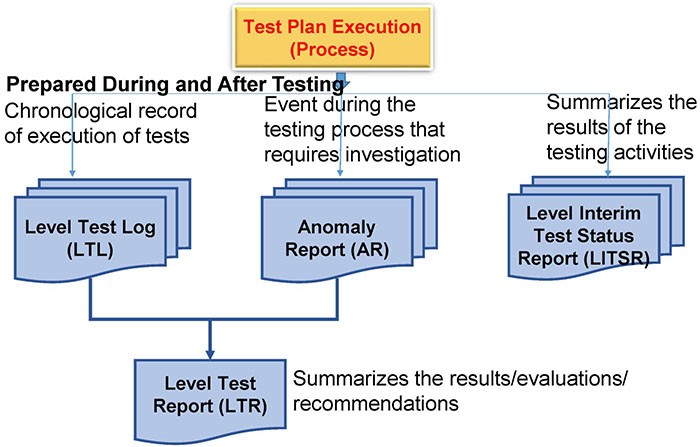
(Extended Text Description: Author's relevant description: This slide shows a Test Plan execution flow chart including Test Logs, Anomaly Report, Test Report and Status graphics in the flow chart. Key Message: This graphic shows the relationships of the documents used in test reporting. Deliverables created during and after test execution include Test Logs, Anomaly Reports, and Test Reports. "Level" means whatever test level you are doing. Examples: Unit test, System, Acceptance, Component, Subsystem, etc. Test reporting documentation is prepared during and after the test execution. Testing reports are used for interpretation and recommendations. Each document purpose is shown next to the box. Consequences of a Poor or No Reporting Documentation in a Specification A tested device and clear evaluation of results will allow the test to continue, terminate, or modify to ensure all errors are removed and a device will operate as intended. Failure will also place the owning agency in legal liability or a loss of service in the field (regardless of the size of effort or agency or small city vs. big city operations).)
Slide 53:

Slide 54:
Question
Which is part of an Agency's ATC Testing Documentation?
Answer Choices
- Scope
- Approach
- Resources and Schedule
- All of the above
Slide 55:
Review of Answers
 a) Scope
Incorrect. Testing scope is always part of the Agency-prepared ATC testing documentation. It should include what is specifically not included in the scope, for clarity.

Incorrect. Test approach is always included to identify equipment needed, for example.
 c) Resources and Schedule
Incorrect. Testing scope and approach without identified and agreed resources and schedule will be unsuccessful.
 d) All of the above
Correct! All are part of the Agency-prepared ATC testing documentation.
Slide 56:
Learning Objectives
- Identify key objects of ATC 5201 Standard equipment for testing documentation
- Describe within the context of a systems engineering lifecycle the role of a test plan and the testing to be undertaken
- Describe the application of good testing documentation for transportation controller equipment based on the ATC 5201 v06 Standard
Slide 57:
Learning Objective 3
- Describe the application of good testing documentation for transportation controller equipment based on the ATC 5201 v06 Standard
Slide 58:
Key Elements of ATC 5201 Standard v06 Tied to What Is Covered by a Test Plan
-
Needs to Requirements Traceability Matrix (NRTM)
- Answers "What needs to be tested"
-
Requirements Traceability Matrix (RTM)
- Answers " What section or part of the standard (design)" is affected
Note: The ATC 5201 v06 standard does NOT provide NRTM and RTM; the user must develop them for testing documentation
Slide 59:
Key Elements of ATC 5201 Standard v06 Tied to What Is Covered by a Test Plan
Summary of a Test Plan (Testing Process)
-
Testing process is about verifying a requirement
- Each (identified) requirement is to be tested
- Each requirement validated by testing is traced to a Test Case in the Requirement Test Case Traceability Matrix (RTCTM)
- Each Test Case lists one or more Test Procedures that end with Pass/Fail declaration
Note: User must develop RTCTM for testing process in the Test Design
Slide 60:
Key Elements of ATC 5201 Standard v06 Tied to What Is Covered by a Test Plan
NRTM Identifies "What Is to Be Tested"
NRTM Contains NEMA TS2 ATC Configuration with Requirements
| UN ID | User Need | FR ID | Functional Requirement | Conformance | Support | Additional Specifications |
|---|---|---|---|---|---|---|
| 6.5.1 | NEMA TS 2 Equipment | 5.2.1 | NEMA TS 2 Type 2 Interfaces | M | Yes | ATC 5201 v06 used with NEMA TS 2 Cabinet Configuration |
| 5.6.1 | NEMA Operating Voltages | M | Yes | |||
| 5.6.2 | NEMA Operating Frequencies | M | Yes | |||
| 5.6.3 | NEMA Power Interruptions | M | Yes | |||
| 7.3.1 | Minimum Display Size | 5.3.3 | Text-Based Display Size | O | Yes/NO | |
Slide 61:
Key Elements of ATC 5201 Standard v06 Tied to What Is Covered by a Test Plan
RTM Traces to HW & SW Objects from Standard for Testing
Requirements to ATC 5201 v06 Standard Cross-Reference
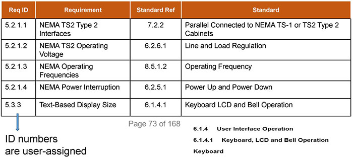
(Extended Text Description: This slide contains the following table and additional text:
| Req ID | Requirement | Standard Ref | Standard |
|---|---|---|---|
| 5.2.1.1 | NEMA TS2 Type 2 Interfaces | 7.2.2 | Parallel Connected to NEMA TS-1 or TS2 Type 2 Cabinets |
| 5.2.1.2 | NEMA TS2 Operating Voltage | 6.2.6.1 | Line and Load Regulation |
| 5.2.1.3 | NEMA Operating Frequencies | 8.5.1.2 | Operating Frequency |
| 5.2.1.4 | NEMA Power Interruption | 6.2.5.1 | Power Up and Power Down |
| 5.3.3 | Text-Based Display Size | 6.1.4.1 | Keyboard LCD and Bell Operation |
Page 73 of 168
The left column points to the text: ID numbers are user-assigned
Additional text below the table reads:
6.1.4 User Interface Operation
6.1.4.1 Keyboard, LCD and Bell Operation
Keyboard
)
Slide 62:
NRTM + RTM Specify Procurement Configuration, Which Answers What an Agency Desires in ATC Units
Both NRTM and RTM are used in the development of an RTCTM, which actually states what will be tested

(Extended Text Description: This slide shows an orange circle with "NTRM", to the right a gray circle with "RTM", to the right a gray "=", to the right a yellow circle with "RTCTM", under headers that read, respectively: Project Needs, Standard, Test will be done according to what is in RTCTM.)
Slide 63:
Key Elements of ATC 5201 Standard v06 Tied to What Is Covered by a Test Plan
RTCTM Traces Each Requirement to Test Cases, Which Are Used in the Testing Process

(Extended Text Description: This slide contains the following text: RTCTM Connects - Requirements to Test Cases to Be Developed, which points to the Requirement and TC ID columns of the following table:
| Rq. ID | Requirement | TC ID | ATC 5201 Reference and Title |
|---|---|---|---|
| FR010 | ATC configuration shall include TS2 Type 2 FIO | TC010 | 7.2.2 Parallel Connections to NEMA TS-1 or TS2 Type 2 Cabinets |
| FR020 | Signal control source code shall compile and load using Board Support Package tool | TC020 | 3.3.1 Board Support Package |
| FR030 | ATC configuration shall include Front Panel | TC030 | 6.1.1 Minimum User Interface |
| FR040 | ATC Front Panel shall include 8 lines for data entry plus 8 lines for status | TC040 | 6.1.4.1 Keyboard, LCD and Bell Operation |
| FR050 | ATC Front panel data entry keys shall conform to the ATC 5201 key codes | TC050 | Table 6-4 Configuration Command Codes |
)
Slide 64:
Key Elements of the Conformance Statement
How Does Test Case Perform Conformance to the ATC Standard?
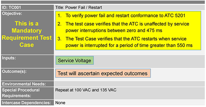
(Extended Text Description: This slide contains the following table:
| ID: TC001 | Title: Power Fail / Restart |
|
Objective: This is a Mandatory Requirement Test Case |
|
| Inputs: | Service Voltage |
| Outcome(s): | Test will ascertain expected outcomes |
| Environmental Needs: | |
| Special Procedural Requirements: | Repeat at 100 VAC and 135 VAC |
| Intercase Dependencies: | None |
)
Slide 65:
Identify Key Elements of ATC 5201 Standard v06 Tied to What Is Covered by a Test Plan
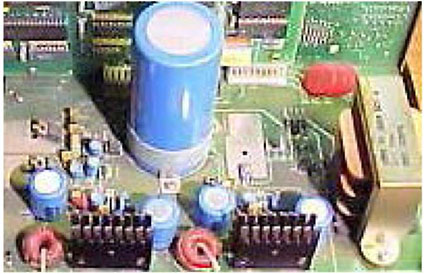
A Test Procedure Is the Last Step in Testing Process; It "Brings Out" Results
Results will confirm expectations (PASS) or NOT confirm (FAIL)
| Step | Test Procedure | Results |
|---|---|---|
| 1 | Set input voltage to 120 VAC | DUT restarts and runs the FIT test |
| 2 | Set input frequency to 60 Hz | DUT runs the FIT test continually |
| 3 | Interrupt the power for 500 ms | DUT issues Power Down, does not restart |
| 4 | Interrupt power for 1,000 ms | DUT issues Power Down and restarts |
Slide 66:
Key Elements of the Conformance Statement
Issues Affecting ATC 5201 v06 Conformance
- ATC 5201 v5.2b was published on 9/25/2006
- After five years, standards are reaffirmed or maintained
- During maintenance, ATC 5201 v5.2b remained in effect
- Once published, ATC 5201 v06 takes effect
- Cannot conform to both v5.2b and v06
Slide 67:
Key Elements of the Conformance Statement
ATC 5201 Standards Conformance Statement from a Manufacturer
Conformance Statement includes the level of conformance and to which version of the 5201 Standard.
Example of a Conformance Statement
| Version | Section | Wording | Implemented |
|---|---|---|---|
|
v5.2b v6.0 |
5.4.3 4.4.3 |
Operates as 4 Serial Peripheral Interface (SPI) device selects Operates as 4-bit binary, 16 SPI devices |
4-bit binary Per v6.0 |
|
v5.2b v6.0 |
8.3 7.3 |
Two internal 100BASE-TX Hub Two internal switches or two VLANS |
Two internal switches |
Slide 68:

Slide 69:
Question
What is the primary purpose of RTCTM? Answer Choices
- Sets the ATC testing workflow sequences
- Correlates ATC User Needs to Requirements
- Contains only ATC test cases
- Traces ATC Requirement to ATC Test Case
Slide 70:
Review of Answers
 a) Sets the testing workflow sequences
Incorrect. Testing workflow is part of the ATC Unit Test Plan.
 b) Correlates User Needs to Requirements
Incorrect. User Needs to Requirements are part of the NRTM, not RTCTM.
 c) Contains only test cases
Incorrect. RTCTM contains test cases with inputs and expected outcomes.
 d) Traces Requirement to Test Case
Correct! RTCTM identifies the Test Cases that will be used to verify each Requirement with one or more test procedures.
Slide 71:
Learning Objectives
- Identify key elements of ATC 5201 Standard equipment for testing documentation
- Describe within the context of a systems engineering lifecycle the role of a test plan and the testing to be undertaken
- Describe the application of good testing documentation for transportation controller equipment based on the ATC 5201 v06 Standard
- Describe the testing of ATC using sample testing documentation
Slide 72:
Learning Objective 4
- Describe the testing of ATC using sample testing documentation
Slide 73:
Applying Testing Documentation to ATC Testing Process
Testing Documentation
- Testing documentation for a given project is driven by procurement configuration
- Documentation is based on IEEE Standard 829 formats
- Test Cases are carried out with one or more Test Procedures
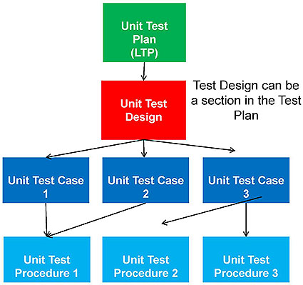
(Extended Text Description: Author's relevant description: This slide shows a flow chart. Single green LTP box at top. Below, single red Unit Test Design box. Below, three dark blue Unit Test Case boxes. Below, three light blue Unit Test Procedure boxes. Key message: Prior to discussing a walkthrough process of a case study, we need to review the background on essential key terms used in a test documentation, starting with Test Plan, Test Cases, Test Procedures. This will help in the discussion on what should be in a Test Plan.)
Slide 74:
Applying Testing Documentation to ATC Testing Process
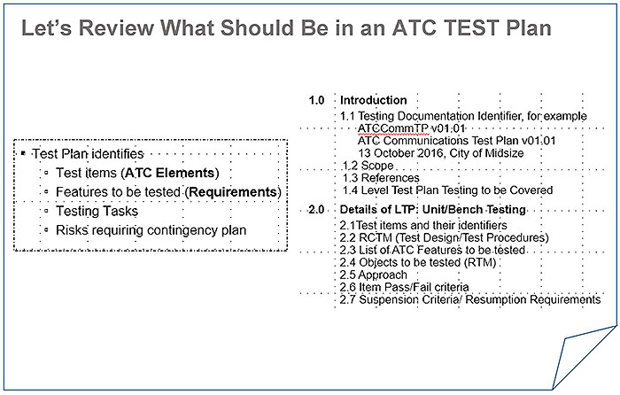
(Extended Text Description: This slide contains the following text:
Let's Review What Should Be in an ATC TEST Plan
-
Test Plan identifies
- Test items (ATC Elements)
- Features to be tested (Requirements)
- Testing Tasks
- Risks requiring contingency plan
1.0 Introduction
1.1 Testing Documentation Identifier, for example
ATCCommTP v0101
ATC Communications Test Plan v01 01 13 October 2016, City of Midsize1.2 Scope
1.3 References
1.4 Level Test Plan Testing to be Covered
2.0 Details of LTP: Unit/Bench Testing
2.1 Test items and their identifiers
2.2 RCTM (Test Design/Test Procedures)
2.3 List of ATC Features to Detested.
2.4 Objects to be tested (RTM)
2.5 Approach
2.6 Item Pass/Fail criteria
2.7 Suspension Criteria/ Resumption Requirements
)
Slide 75:
Applying Testing Documentation to ATC Testing Process
Let's Review What Should Be in an ATC TEST Plan (cont.)
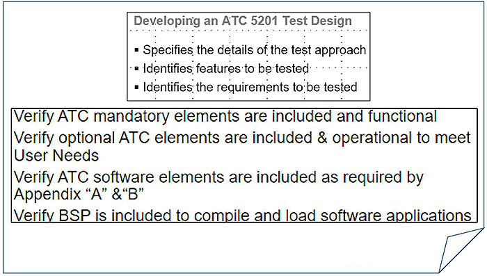
(Extended Text Description: This slide contains the following text:
Developing an ATC 5201 Test Design
- Specifies the details of the test approach
- Identifies; features to be tested
- Identifies the requirements to be tested
Verify ATC mandatory elements are included and functional
Verify optional ATC elements are included & operational to meet User Needs
Verify ATC software elements are included as required by Appendix "A" &"B"
Verify BSP is included to compile and load software applications
)

Slide 76:
Applying Testing Documentation to ATC Testing Process
Let's Review What Should Be in an ATC TEST Plan (cont.)

(Extended Text Description: This slide contains the following text:
Developing an ATC 5201 Test Design
- Specifies the details of the test approach
- Identifies features to be tested
- Identifies the requirements to; be tested
Verify ATC mandatory elements are included and functional
Verify optional ATC elements are included & operational to meet User Needs
Verify ATC software elements are included as required by Appendix "A" & "B"
Verify BSP is included to compile and load software applications
Verify fitness, test, source code is included
Verify that BSP can compile and load fitness test into ATC:
Verify that BSP can compile and load signal control or other applications
Verify environmental compliance, either
- Create Test Plan and conduct environmental tests per ATC:5201 v06 Section 8, or
- Require copy of independent laboratory tests per ATC 5201 v06 Section 8
)

Slide 77:
Applying Testing Documentation to ATC Testing Process
ATC Testing Process
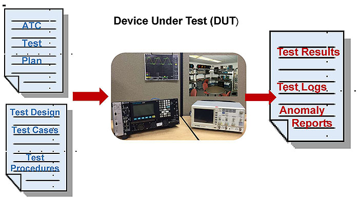
(Extended Text Description: Author's relevant description: This slide has ATC Test page graphic in upper left, Test Design graphic in lower left, Test Results graphic in upper right and photo of ATC and test equipment in center.)
Slide 78:

Slide 79:
Apply the Process and Write a Test Plan to Verify ATC 5201 v06 Requirements
Case Study for TS2 Type 2 Cabinet Retrofit
Our Approach to the ATC Test Plan
- Configure ATC from Core & Options
- Prepare testing plan
- Include it in ATC Procurement Specification


Slide 80:
Apply the Process and Write a Test Plan to Verify ATC 5201 v06 Requirements
Case Study for TS2 Type 2 Cabinet Retrofit
City of Midsize ATC Procurement Specification
- Retrofit of ATC into NEMA TS2 Type 2 electrical cabinets
- Compatible with existing Traffic Signal Control software application
- Front panel text display of controller status and keys for data entry
- Ethernet IP communications, no serial modems
- Project User Needs of each stakeholder and RTM are included
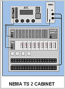

Slide 81:
Apply the Process and Write a Test Plan to Verify ATC 5201 v06 Requirements
Case Study for TS2 Type 2 Cabinet Retrofit
Our Approach to the ATC Test Plan
- First examine and determine: configure ATC from Core and Options
- Second, prepare testing plan; test design that includes configuration
- Test Plan itself is made part of ATC contact documentation
Given:
TS2 Type 1 Wiring
Existing Signal Control App
Text Data Entry
IP Comm

Slide 82:
Apply the Process and Write a Test Plan to Verify ATC 5201 v06 Requirements
Let's Determine What Needs to Be Tested
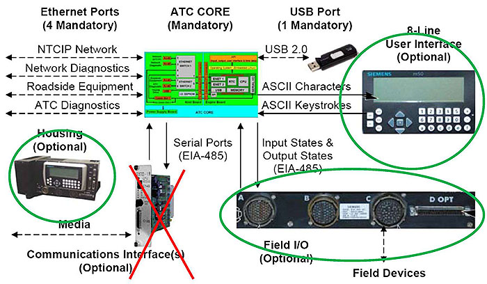
(Extended Text Description: Author's relevant description: This slide has a graphics of the Core, Housing, User Interface and Field I/O, with the Field I/O, Housing and User Interface circled in green, and the Communication Interface with a superimposed red "X". Key Message: Project parameters are listed that need to be verified and will be included in a sample test plan. This slide also reiterates purpose of ATC in actual deployments. In this Use Case, we first configure the ATC by starting with the mandatory Core of objects, and then add or subtract the optional objects of the ATC 5201 standard that are needed to meet the project requirements. In this Use Case the configuration results in the following Optional objects: Optional 8-Line User Interface that is familiar to the maintenance staff, Optional Field I/O for NEMA TS2 cabinet wiring, Optional Shelf Mount Housing, No Communications Interface is required, as the ATC is required to communicate via Ethernet IP. Therefore, the Test Plan will include tests for User Interface, NEMA TS2 Inputs and Outputs, and fit to the available shelf space. No test plan is needed for communications interface module.)
Slide 83:
Apply the Process and Write a Test Plan to Verify ATC 5201 v06 Requirements
Let's List What Needs to Be Tested in This Use Case
- Mandatory Core
- Ethernet Ports
- User Interface front panel
- TS2 Type 2 Parallel I/O
- Shelf-mount housing

Slide 84:
Apply the Process and Write a Test Plan to Verify ATC 5201 v06 Requirements
Verify Mandatory Objects of ATC 5201 v06 for Compliance Mandatory Objects to Be Tested
- 1. Engine Board interchangeable among manufacturers
- Host Module that accepts the Engine Board
- Power Supply that converts service power to voltages and control signals
- Linux Operating System and drivers per ATC 5201 v06 Appendix "A" &"B"
- Board Support Package of software development tools and libraries
- Diagnostic and Acceptances Test source code and instructions
Slide 85:
Apply the Process and Write a Test Plan to Verify ATC 5201 v06 Requirements
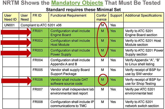
(Extended Text Description: This slide contains the following text and table:
NRTM Shows the Mandatory Objects That Must Be Tested
Standard requires these Minimal Set
| User Need ID | User Need | FR ID | Functional Requirement | Conformance | Support | Additional Specifications |
|---|---|---|---|---|---|---|
| UN001 | Compliant to ATC 5201 v06 | M | Yes | |||
| FR001 | Configuration shall include Engine Board | M | Yes | Verify to ATC 5201 Engine Board section | ||
| FR002 | Configuration shall include Host Module | M | Yes | Verify to ATC 5201 Host Module section | ||
| FR003 | Configuration shall include Power Supply | M | Yes | Verify to ATC 5201 Power Supply section | ||
| FR004 | Configuration shall include Appendix A and B | M | Yes | Verify Appendix "A", "B" to Linux shell listing | ||
| FR005 | Vendor shall supply Board Support Package | M | Yes | Verify receipt of BSP for use by SW vendor | ||
| FR006 | Vendor shall include DAT software source code | M | Yes | Verify receipt of BSP for use for Shop Testing | ||
| FR007 | Vendor shall independent lab environmental test report | M | Yes | Verify per ATC 5201 environmental test | ||
| FR008 | Configuration shall include IP communications to TMC | M | Yes | Verify to ATC 5201 network switch section | ||
In the table, Rows FR001, FR002, FR003 and FR006 have read arrows with their Conformance cells circled in red.)
Slide 86:
Apply the Process and Write a Test Plan to Verify ATC 5201 v06 Requirements
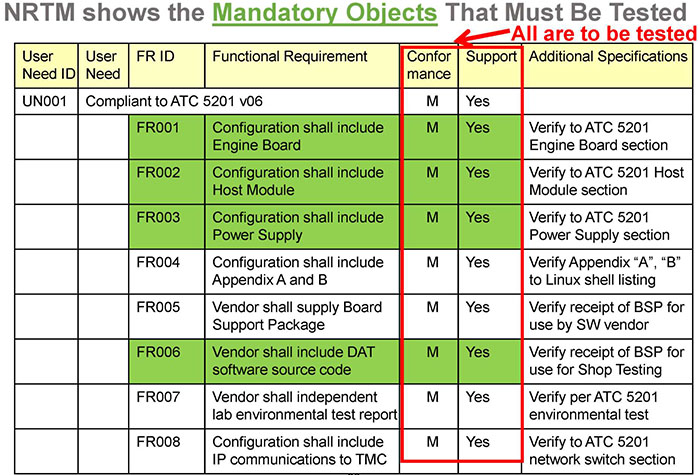
(Extended Text Description: This slide contains the following text and table:
NRTM Shows the Mandatory Objects That Must Be Tested
| User Need ID | User Need | FR ID | Functional Requirement | Conformance | Support | Additional Specifications |
|---|---|---|---|---|---|---|
| UN001 | Compliant to ATC 5201 v06 | M | Yes | |||
| FR001 | Configuration shall include Engine Board | M | Yes | Verify to ATC 5201 Engine Board section | ||
| FR002 | Configuration shall include Host Module | M | Yes | Verify to ATC 5201 Host Module section | ||
| FR003 | Configuration shall include Power Supply | M | Yes | Verify to ATC 5201 Power Supply section | ||
| FR004 | Configuration shall include Appendix A and B | M | Yes | Verify Appendix "A", "B" to Linux shell listing | ||
| FR005 | Vendor shall supply Board Support Package | M | Yes | Verify receipt of BSP for use by SW vendor | ||
| FR006 | Vendor shall include DAT software source code | M | Yes | Verify receipt of BSP for use for Shop Testing | ||
| FR007 | Vendor shall independent lab environmental test report | M | Yes | Verify per ATC 5201 environmental test | ||
| FR008 | Configuration shall include IP communications to TMC | M | Yes | Verify to ATC 5201 network switch section | ||
Additionally, the text "All art to be tested" has a red arrow pointing to the Conformance and Support columns, which are highlighted in red.)
Slide 87:
Apply the Process and Write a Test Plan to Verify ATC 5201 v06 Requirements
(Extended Text Description: This slide contains the following text and table:
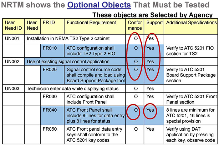
NRTM Shows the Optional Objects That Must Be Tested
| User Need ID | User Need | FR ID | Functional Requirement | Conformance | Support | Additional Specifications |
|---|---|---|---|---|---|---|
| UN001 | Installation in NEMA TS2 Type 2 cabinet | O | Yes | |||
| FR010 | ATC configuration shall include TS2 Type 2 FIO | O | Yes | Verify to ATC 5201 FI0 section for TS2 | ||
| UN002 | Use of existing signal control application | O | Yes | |||
| FR020 | Signal control source code shall compile and load using Board Support Package tool | O | Yes | Verify to ATC 5201 Board Support Package section | ||
| UN003 | Technician enter data while displaying status | O | Yes | |||
| FR030 | ATC configuration shall include Front Panel | O | Yes | Verify to ATC 5201 Front Panel section | ||
| FR040 | ATC Front Panel shall include 8 lines for data entry plus 8 lines for status | O | Yes | 8 lines are minimum for ATC 5201, 16 lines is special provision | ||
| FR050 | ATC Front panel data entry keys shall conform to the ATC 5201 key codes | O | Yes | Verify using DAT application by pressing each key, observe code | ||
Additionally, there is text at the top of the table that says: These objects are selected by Agency, with the 2-5th and 8th rows of the Conformance and Support columns circled in red.)
Slide 88:
Apply the Process and Write a Test Plan to Verify ATC 5201 v06 Requirements
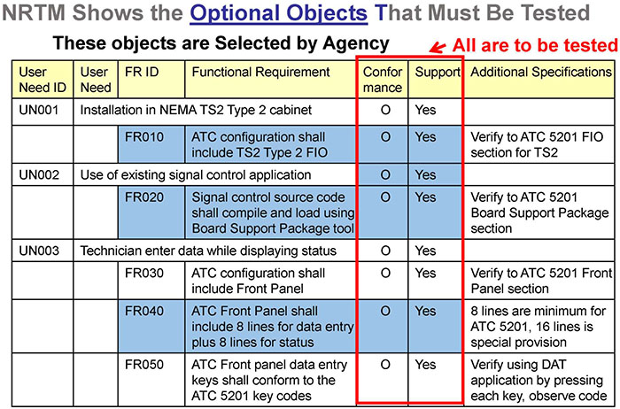
(Extended Text Description: This slide contains the following text and table:
NRTM Shows the Optional Objects That Must Be Tested
| User Need ID | User Need | FR ID | Functional Requirement | Conformance | Support | Additional Specifications |
|---|---|---|---|---|---|---|
| UN001 | Installation in NEMA TS2 Type 2 cabinet | O | Yes | |||
| FR010 | ATC configuration shall include TS2 Type 2 FIO | O | Yes | Verify to ATC 5201 FI0 section for TS2 | ||
| UN002 | Use of existing signal control application | O | Yes | |||
| FR020 | Signal control source code shall compile and load using Board Support Package tool | O | Yes | Verify to ATC 5201 Board Support Package section | ||
| UN003 | Technician enter data while displaying status | O | Yes | |||
| FR030 | ATC configuration shall include Front Panel | O | Yes | Verify to ATC 5201 Front Panel section | ||
| FR040 | ATC Front Panel shall include 8 lines for data entry plus 8 lines for status | O | Yes | 8 lines are minimum for ATC 5201, 16 lines is special provision | ||
| FR050 | ATC Front panel data entry keys shall conform to the ATC 5201 key codes | O | Yes | Verify using DAT application by pressing each key, observe code | ||
Additionally, there is text at the top of the table that says: "These objects are selected by Agency." Also, the text "All art to be tested" has a red arrow pointing to the Conformance and Support columns, which are highlighted in red.)
Slide 89:
Test Traceability Matrix
ATC 5201 Test Traceability
Traceability: Requirements to Test Case to Test Procedure
| Req ID | Req | Test Case ID | Test Case | Test Proc ID | Test Procedure |
|---|---|---|---|---|---|
| FR001 | The DUT shall not restart when subjected to power interruption of < 500 ms | ||||
| TC001 | Power Fail Immunity: Power Interruption of < 500 ms | ||||
| TP001 | Verify DUT operation is unaffected | ||||
| TP003 | Verify no Power Down signal | ||||
| TC002 | Restart Operation: Power Failure of > 1,000 ms | ||||
| TP004 | Verify DUT restarts | ||||
| TP005 | Verify Power Down signal | ||||
| FR002 | The DUT shall maintain time of day during power failures | ||||
| TC 003 | Time Accuracy during variable power failures | ||||
| TP006 | 500 ms: Verify time accuracy | ||||
| TP007 | 1 hour: Verify time accuracy | ||||
Slide 90:
Apply the Process and Write a Test Plan to Verify ATC 5201 v06 Requirements
Prepare RTCTM for Testing Documentation
| All requirements from NRTM now entered in RTCTM | Each requirement traced to a design-Element in the standard sections | ||
| Req ID | Requirement | TC ID | ATC 5201 Reference and Title |
|---|---|---|---|
| FR010 | ATC configuration shall include TS-2 Type 2 FIO | TC010 | 7.2.2 Parallel Connections to NEMA TS-1 or TS-2 Type 2 Cabinets |
| FR020 | Signal control source code shall compile and load using Board Support Package tool | TC020 | 3.3.1 Board Support Package |
| FR030 | A1C configuration shall include Front Panel | TC030 | 6.1.1 Minimum User Interface |
| FR040 | ATC Front Panel shall include 8 lines for data entry plus 8 lines for status | TC040 | 6.1.4.1 Keyboard, LCD and Bell Operation |
| FR050 | ATC Front panel data entry keys shall conform to the ATC 5201 key: codes | TC050 | Table 6-4 Configuration Command Codes |
A Test Case will be carried out in testing process
Slide 91:
Address Consequences of Testing Boundary and Error Conditions
Check for Error Conditions
-
Positive testing:
- Validate input value, i.e., Key Code
- Expected outputs from Device Under Test (DUT) in Table 6-6
-
Negative testing:
- Assert invalid input values or sequences per the test procedure, such as invalid key codes.
- Errors are examined for next action on test continuity.
See Table 6-6: Key Press Codes
| Key | ASCII DATA (TEXT) | ASCII DATA (HEX) |
|---|---|---|
| 0 | 0 | 30 |
| 1 | 1 | 31 |
| 2 | 2 | 32 |
| 3 | 3 | 33 |
| 4 | 4 | 34 |
| 5 | 5 | 35 |
| 6 | 6 | 36 |
| 7 | 7 | 37 |
| 8 | 8 | 38 |
| 9 | 9 | 39 |
| A | A | 40 |
| B | B | 41 |
| C | C | 42 |
| D | D | 43 |
| E | E | 44 |
| F | F | 45 |
| (UP ARROW) | ESC [ A | 1B 4F 41 |
| (DOWN ARROW) | ESC [ B | 1B 4F 42 |
| (RIGHT ARROW) | ESC [ C | 1B 4F 43 |
| (LEFT ARROW) | ESC [ D | 1B 4F 44 |
| ESC | ESC O S | 1B 4F 53 |
| NEXT | ESC O P | 1B 4F 50 |
| YES | ESC O Q | 1B 4F 51 |
| NO | ESC O R | 1B 4F 52 |
| * | * | 2A |
| + | + | 2B |
| - | - | 2D |
| ENTER | CR | 0D |
| Double Key Press (P1; P2) | ESC [ K P1 P2 | 1B 5B 4B P1 P2 |
| Vendor Specific Key 1 | ESC O V | 1B 4F 56 |
| Vendor Specific Key 2 | ESC O W | 1& IF 57 |
| Vendor Specific Key 3 | ESC O X | 1B 4F 58 |
| Vendor Specific Key 4 | ESC O Y | 1B 4F 59 |
| Vendor Specific Key 5 | ESC O Z | 1B 4F 5A |
| Vendor Specific Key 6 | ESC O [ | 1B 4F 5B |
| Vendor Specific Key 7 | ESC O \ | 1& IF 5C |
| Vendor Specific Key 8 | ESC O ] | 1B 4F 5D |
| Vendor Specific Key 9 | ESC O ^ | 1B 4F 5E |
| Vendor Specific Key 10 | ESC O _ | 1B 4F 5F |
| Vendor Specific Key 11 | ESC O ' | 1B 4F 60 |
| Vendor Specific Key 12 | ESC O a | 1& IF 61 |
| Vendor Specific Key 13 | ESC O b | 1B 4F 62 |
| Vendor Specific Key 14 | ESC O c | 1B 4F 63 |
| Vendor Specific Key 15 | ESC O d | 1B 4F 64 |
| Vendor Specific Key 16 | ESC O e | 1B 4F 65 |
Slide 92:
Address Consequences of Testing Boundary and Error Conditions
Testing for Boundary Conditions
-
All boundary conditions are tested:
- Just below each limit
- Just above each limit
- Exactly on each limit
-
Boundary is valid, DUT should:
- Process successfully
- Respond accordingly
-
If error conditions occur, DUT should:
- Respond with error message
- Remain in normal operation
- No communications loss
Slide 93:
Address Consequences of Testing Boundary and Error Conditions
Example: Testing for Boundary Conditions
| ID: TC001 | Title: Power Fail / Restart |
| Objective: |
To verify power fail and restart conformance to ATC 5201 The test case verifies that the ATC is unaffected by service power interruptions between zero and 475 ms The Test Case verifies that the ATC restarts when service power is interrupted for a period of time greater than 550 ms |
| Inputs: | Service Voltage |
| Outcome(s): |
475 ms interruption: ATC operation is unaffected, ATC time clock does not drift 550 ms, 750 ms and 1000 ms interruptions: ATC restarts |
| Environmental Needs: | Room temperature, power interruption measured by oscilloscope |
| Special Procedural Requirements: | Repeat at 100 VAC and 135 VAC |
| Intercase Dependencies: | None |
Slide 94:
Address Consequences of Testing Boundary and Error Conditions
Example: Testing for Boundary Conditions
| Test # | Service VAC | OFF ms | Expected | Actual |
|---|---|---|---|---|
| TC1.1 | 100 | 475 | Unaffected | |
| TC1.2 | 100 | 475 | Unaffected | |
| TC1.3 | 100 | 475 | Unaffected | |
| TC1.4 | 100 | 550 | Restart | |
| TC1.5 | 100 | 750 | Restart | |
| TC1.6 | 100 | 1000 | Restart | |
| TC1.7 | 135 | 475 | Unaffected | |
| TC1.8 | 135 | 475 | Unaffected | |
| TC1.9 | 135 | 475 | Unaffected | |
| TC1.10 | 135 | 550 | Restart | |
| TC1.11 | 135 | 750 | Restart | |
| TC1.12 | 135 | 1000 | Restart |
Slide 95:
Test Tools and Equipment Available
ATC Testing Tools Available
- DAT is not a required deliverable for compliance to ATC 5201, but typically available from ATC manufacturers
- DAT is delivered as Source Code
- DAT is compiled and loaded into ATC using the BSP
- DAT instructions inform the operator how to compile, link, and load the DAT
- Executing the DAT performs a self-test of the ATC hardware, operating system, and low-level drivers
- Once DAT executes successfully, other applications such as signal control can be loaded in place of the DAT
- Operational failures can then be attributed to the application, not the ATC or Linux components
- Custom-made loopback cables from Input to Output are typical
Slide 96:
Available Training Modules
Professional Capacity Building (PCB) Training Available
-
Additional Information on Test Design, Test Cases, and Test Procedures:
- T203a How to Develop Test Cases for an ITS Standards-Based Test Plan Part 1 of 2
- T203b How to Develop Test Cases for an ITS Standards-Based Test Plan Part 2 of 2
- T204a How to Develop Test Procedures for ITS Standards-Based Test Plan, Part 1 of 2
- T204b How to Develop Test Procedures for ITS Standards-Based Test Plan, Part 2 of 2
- T312 Applying Your Test Plan to a Transportation Sensor System (TSS) Based on the NTCIP 1209 Standard v02
- T309 Applying Your Test Plan to Ramp Meter Control (RMC) Units Based on the NTCIP 1207 Standard v02
Slide 97:

Slide 98:
Question - True or False
Manufacturer will have a single ATC that conforms to all versions of the ATC 5201 Standard?
Answer Choices
- True
- False
Slide 99:
Review of Answers
 a) True
Incorrect. Versions of ATC 5201 contain conflicting sections, so that no ATC conforms to all versions.
 b) False
Correct! Manufacturer supplies a Conformance Statement that covers the ATC 5201 version and includes a list of items that could affect software compatibility.
Slide 100:
Module Summary
- Identify key elements of ATC 5201 Standard equipment for testing documentation
- Describe within the context of a systems engineering lifecycle the role of a test plan and the testing to be undertaken
- Describe the application of good testing documentation for transportation controller equipment based on the ATC 5201 v06 Standard
- Describe the testing of ATC using sample testing documentation
Slide 101:
We have Now Completed the ATC Curriculum
 Module A307a:
Understanding User Needs for Advanced Transportation Controllers Based on ATC 5201 Standard v06.
 Module A307b:
Understanding Requirements for Advanced Transportation Controllers Based on ATC 5201 Standard v06.
 Module T307:
Applying Your Test Plan to the Advanced Transportation Controller Based on ATC 5201 Standard v06.
Slide 102:
Thank you for completing this module.
Feedback
Please use the Feedback link below to provide us with your thoughts and comments about the value of the training.
Thank you!