ITS Transit Standards Professional Capacity Building Program
Module 2: Transit Management Standards, Part 1 of 2
HTML of the PowerPoint Presentation
(Note: This document has been converted from a PowerPoint presentation to 508-compliant HTML. The formatting has been adjusted for 508 compliance, but all the original text content is included, plus additional text descriptions for the images, photos and/or diagrams have been provided below.)
Slide 1:
(Extended Text Description: Welcome - Graphic image of introductory slide. A large dark blue rectangle with a wide, light grid pattern at the top half and bands of dark and lighter blue bands below. There is a white square ITS logo box with words "Standards ITS Training" in green and blue on the middle left side. The word "Welcome" in white is to the right of the logo. Under the logo box is the logo for the U.S. Department of Transportation, Office of the Assistant Secretary for Research and Technology.)
Slide 2:

(Extended Text Description: This slide, entitled "Mac Lister" has a photo of Mac Lister, Program Manager Knowledge and Technology Transfer, ITS Joint Program Office, on the left hand side, with his email address, Mac.Lister@dot.gov. A screen capture snapshot of the home webpage is found on the right hand side - for illustration only - from August 2014. Below this image is a link to the current website: www.its.dot.gov/pcb - this screen capture snapshot shows an example from the Office of the Assistant Secretary for Research and Development - Intelligent Transportation Systems Joint Program Office - ITS Professional Capacity Building Program/Advanced ITS Education. Below the main site banner, it shows the main navigation menu with the following items: About, ITS Training, Knowledge Exchange, Technology Transfer, ITS in Academics, and Media Library. Below the main navigation menu, the page shows various content of the website, including a graphic image of professionals seated in a room during a training program. A text overlay has the text Welcome to ITS Professional Capacity Building. Additional content on the page includes a box entitled What’s New and a section labeled Free Training. Again, this image serves for illustration only. The current website link is: https://www.its.dot.gov/pcb.)
Slide 3:

(Extended Text Description: This slide, entitled "Jeffrey Spencer" has a photo of Jeffrey Spencer, ITS Team Leader, Federal Transit Administration, Office of Research, Demonstration and Innovation, on the left hand side, with his email address, Jeffrey.Spencer@dot.gov. A screen capture snapshot of the home webpage is found on the right hand side - for illustration only - which is the same screen snapshot from Slide 2. Below this image and to the right is the Federal Transit Administration (FTA) logo.)
Slide 4:

Slide 5:
ITS Transit Standards Professional Capacity Building Program
Module 2:
Transit Management Standards, Part 1 of 2
Slide 6:
Instructor

Carol L. Schweiger, Vice President
TranSystems Corporation
Boston, MA
Slide 7:
Target Audience
- Transit management staff (e.g., department heads and senior management) who are considering introducing or upgrading technology to meet operational and customers’ needs;
- Transit agency procurement and grants staff; and
- Transit technology vendors and consultants.
Slide 8:
Recommended Prerequisite(s)

(Extended Text Description: Recommended Prerequisites(s) chart. Two rows with four columns. The far left column is the Module title column: Module 1. The top tier of rows has three columns: Decision Maker, Project Manager, and Project Engineer. The cells below these columns all have check marks in them, signifying that Module 1 should be taken as a prerequisite by the Decision Maker, Project Manager, and Project Engineer.)
-
Recommend prior knowledge includes:
- General understanding of transit technology used in operations, planning, and maintenance
- Basic understanding of transit-related portions of the National ITS Architecture
Slide 9:
Curriculum Path (Decision-Maker)

(Extended Text Description: Curriculum Path for Decision Maker: A graphical illustration indicating the sequence of training modules and where this module fits in. Each module is represented by a box with the name of the module in it and a flow chart showing the logical flow of the modules with the current module boxed in red. The first three boxes are green and aligned horizontally, green signifying "Recommended Pre-requisites." The first box is "Introduction to ITS Transit Standards, Module 1." Below that, connected by a line, is a box with the text "Transit Management, Part 1 of 2", which is outlined in red. Below that, connected by a line, is a box with the text, "TCIP, Part 1 of 2." From here, the lines branch out into three text boxes that are horizontally sequenced and are in blue, signifying "Optional Modules." These three boxes are: "Traveler Information, Part 1 of 2", "Electronic Fare Payment Systems," and "Transit and the Connected Vehicle Environment/Emerging Technologies, Applications, and Future Platforms.")
Slide 10:
Curriculum Path (Project Manager)
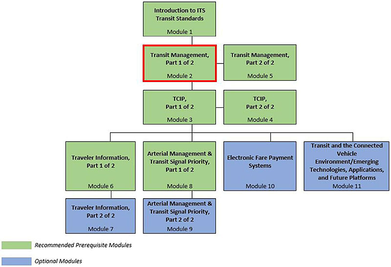
(Extended Text Description: Curriculum Path for Project Manager: A graphical illustration indicating the sequence of training modules and where this module fits in. Each module is represented by a box with the name of the module in it and a flow chart showing the logical flow of the modules with the current module boxed in red. The first three horizontally sequenced boxes are green. The first box is "Introduction to ITS Transit Standards, Module 1." Below that, connected by a line, is a box with the text "Transit Management, Part 1 of 2", which is outlined in red. To the right of this box, is "Transit Management, Part 2 of 2". Below that "Transit Management, Part 1 of 2", connected by a line, is a box with the text, "TCIP, Part 1 of 2." To the right of this box, is "TCIP, Part 2 of 2." From here, the lines branch out into four text boxes that are horizontally sequenced. The first two: "Traveler Information, Part 1 of 2" and "Arterial Management & Transit Signal Priority, Part 1 of 2" are green; the last two are "Electronic Fare Payment Systems," and "Transit and the Connected Vehicle Environment/Emerging Technologies, Applications, and Future Platforms." Below "Traveler Information, Part 1 of 2," is the text box "Traveler Information, Part 2 of 2 coded in blue. Below "Arterial Management & Transit Signal Priority, Part 1 of 2", is the text box "Arterial Management & Transit Signal Priority, Part 2 of 2, coded in blue.)
Slide 11:
Curriculum Path (Project Engineer)

(Extended Text Description: Curriculum Path for Project Engineer: A graphical illustration indicating the sequence of training modules and where this module fits in. Each module is represented by a box with the name of the module in it and a flow chart showing the logical flow of the modules with the current module boxed in red. The first three horizontally sequenced boxes are green. The first box is "Introduction to ITS Transit Standards, Module 1." Below that, connected by a line, is a box with the text "Transit Management, Part 1 of 2", which is outlined in red. To the right of this box, is "Transit Management, Part 2 of 2". Below that "Transit Management, Part 1 of 2", connected by a line, is a box with the text, "TCIP, Part 1 of 2." To the right of this box, is "TCIP, Part 2 of 2." From here, the lines branch out into four text boxes that are horizontally sequenced. The first two: "Traveler Information, Part 1 of 2" and "Arterial Management & Transit Signal Priority, Part 1 of 2" are green; the last two are "Electronic Fare Payment Systems," and "Transit and the Connected Vehicle Environment/Emerging Technologies, Applications, and Future Platforms." Below "Traveler Information, Part 1 of 2," is the text box "Traveler Information, Part 2 of 2 coded in green. Below "Arterial Management & Transit Signal Priority, Part 1 of 2", is the text box "Arterial Management & Transit Signal Priority, Part 2 of 2, coded in green.)
Slide 12:
Learning Objectives
- Describe (in overview terms) how transit management functions and systems fit into the National ITS Architecture
- Describe the core functions and taxonomy of Transit Management systems
- Briefly describe the functions of systems within the Transit Management taxonomy, and briefly identify the relationships and data exchange among Transit Management systems, Traveler Information, Transit Signal Priority, and Fare Collection systems
- Explain the role of systems engineering and standards in procurement
Slide 13:
Learning Objective #1: Describe (in overview terms) how transit management functions and systems fit into the National ITS Architecture
- Brief review of key concepts of National ITS Architecture (using Module 1 as a reference), including National ITS Architecture layers
- Explain Public Transportation Service Packages
- Explain related Service Packages (e.g., Interactive Traveler Information)
Slide 14:
Learning Objective #1
National ITS Architecture
- Provides a common framework for planning, defining, and integrating ITS
-
The Architecture defines:
- The functions that are required for ITS
- The physical entities or subsystems where these functions reside
- The information flows that connect these physical subsystems
- Template for the development of Regional ITS Architectures
Slide 15:
Learning Objective #1
Architecture Layers
Main Point: Architecture framework comprised of two technical layers, which must operate in the context of an Institutional Layer.
- Institutional Layer - institutions, policies, funding mechanisms and processes required for effective ITS implementation, operation, and maintenance. Shown as base because solid institutional support and effective decisions are prerequisite to an effective ITS program
- Transportation Layer - where transportation solutions defined
- Communications Layer provides for accurate and timely exchange of information between systems to support transportation solutions

(Extended Text Description: Architecture Layers: This is an illustration of the National System Architecture. This architecture helps to define the interfaces and system requirements. There are three layers of the graphic. The top layer is labeled "Communications." The middle layer is labeled "Transportation." The bottom layer is labeled "Institutional." Each layer has topics that need to be considered during the planning process. These are identified in white boxes. On the top "Communications" layer, the areas of consideration are: wireline, wide area wireless, and short range wireless. On the middle "Transportation" layer, the areas of consideration are: Infrastructure, Travelers, Roadways, Vehicles, and Management/Control Centers. On the bottom "Institutional" layer, the areas of consideration are: Enforcement, Emergency, DOTs, YNP, and Chambers of Commerce. In between and to the right of the "Communication" and "Transportation" layers, there is an "Interfaces" label with an arrow above pointing up, and an arrow below pointing down to the "Recommendations" label which sits to the right of the "Transportation" level. Below the "Recommendations" level, there are two arrows – one pointing up, and one pointing down. The arrow pointing down points to the label "Objectives & Requirements" which sits to the right of the "Institutional" level.)
Slide 16:
Learning Objective #1
Architecture View
Main Point: Interconnected presentation of all of the components of the National ITS Architecture
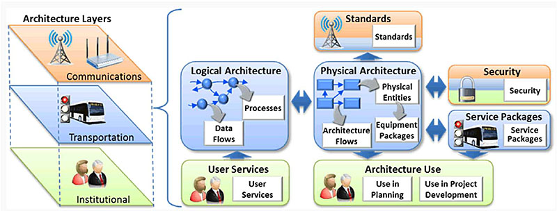
(Extended Text Description: Architecture View: This graphic illustration demonstrates the architectural view of ITS. On the left side, there are three stacked levels labeled Architecture Layers, from top to bottom: Communications (orange, icons of a transmission tower and wireless device), Transportation (blue, icon of a bus and traffic signal), and Institutional (green, icons of people). These three levels are bracketed to relate to the elements on the right side of the diagram, which includes seven elements. Starting from the center is a box in blue labeled Physical Architecture, with a flow chart of interconnected boxes directing to "Architecture Flows" and "Physical Entities" which then directs to "Equipment Packages." This center box relates to several items around it. It relates to an element labeled Standards (above, orange, with icon of transmission tower) and another element labeled Architecture Use (below, green, icons of people, with words "Use in Planning," and "Use in Project Development"). The center elements also relates to and from another element labeled Security (orange, blue, green, icon of padlock), an element labeled Service Packages (blue, icons of bus and traffic signal), and an element labeled Logical Architecture (to the left, blue, interconnected spheres pointing to "Processes" and "Data Flows"). An element labeled User Services (green, icons of people) points to the Logical Architecture element above it.)
Slide 17:
Learning Objective #1
Purpose of Standards in an Architecture
Main Point: Standards have a role in the National ITS Architecture as well as Regional ITS Architectures and Project Architecture
- Fundamental to open ITS environment
- Facilitate deployment of interoperable systems
- This figure shows relationship between ITS standards and architectures
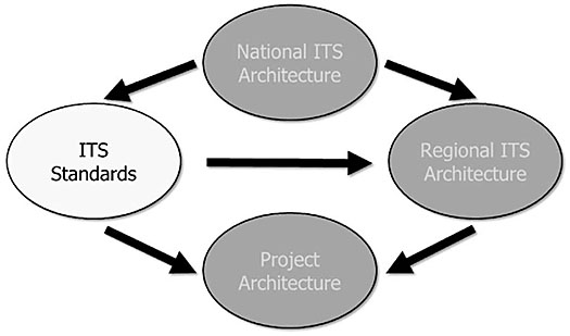
(Extended Text Description: Purpose of Standards in an Architecture: This graphic has 4 ovals, one for the National ITS Architecture, one for ITS Standards, one for Regional ITS Architecture and one for Project Architecture. The National ITS Architecture oval is at the top and is connect by lines with arrows to the ITS Standards oval and the Regional Architecture oval, which are side-by-side. The ITS Standards oval is connected by lines with arrows to the Regional ITS Architecture oval and the Project Architecture oval. The Regional ITS Architecture oval is connected by a line with an arrow to the Project Architecture oval. The ITS Standards oval is white and the text is in black. The other three ovals are gray with black letters.)
Slide 18:
Learning Objective #1
Service Packages (SPs)
- Represent slices of Physical Architecture
- Collects subsystems, equipment packages, and architecture flows that provide desired service
-
There are 11 public transportation SPs:
- Transit Vehicle Tracking
- Transit Fixed-Route Operations
- Demand Response Transit Operations
- Transit Fare Collection Management
- Transit Security
Slide 19:
Learning Objective #1
Service Packages (SPs) (cont.)
(11 public transportation SPs cont.)
- Transit Fleet Management
- Multi-modal Coordination
- Transit Traveler Information
- Transit Signal Priority
- Transit Passenger Counting
- Multimodal Connection Protection
Slide 20:
Learning Objective #1
Transit Management Service Package Example
Main Point: An example of one transit SP diagram

(Extended Text Description: Transit Management Service Package Example: This graphic has a rectangular box in the center which is labeled Transit Management and is purple in color. Within Transit Management is another smaller rectangle labeled Transit Center Vehicle Tracking and is white in color. Above the Transit Management box is an oval labeled Map Update Provider, which is yellow in color. There is a line with an arrow from Transit Management to the Map Update Provider oval, which is labeled "map update request." There is a line with an arrow from the Map Update Provider oval to Transit Management, which is labeled "map updates." To the right of Transit Management is a rectangle labeled Transit Vehicle, which is purple in color. Inside Transit Vehicle is another smaller rectangle labeled On-board Transit Trip Monitoring, which is white in color. Above the Transit Vehicle box is an oval labeled Basic Transit Vehicle, which is yellow in color. There is a line with an arrow from the Basic Transit Vehicle oval to Transit Vehicle, which is labeled "transit vehicle measures." There are two lines with arrows from Transit Vehicle to Transit Management, which are labeled "transit vehicle location data" and "transit vehicle schedule performance." Below the Transit Vehicle box is an oval labeled Location Data Source, which is yellow in color. There is a line with an arrow from the Location Data Source oval to Transit Vehicle, which is labeled "position fix." To the left of Transit Management is a rectangle labeled Information Service Provider, which is white in color with cross-hatching. Below the Information Service Provider box is a box labeled Traffic Management, which is white in color with cross-hatching. There are two lines with arrows from Transit Management to Information Service Provider, which are labeled "transit schedule adherence information" and "transit probe data." There is a line with an arrow from Transit Management to Traffic Management, which is labeled "transit probe data." This service package monitors current transit vehicle location using an Automated Vehicle Location System. The location data may be used to determine real time schedule adherence and update the transit system’s schedule in real-time. Vehicle position may be determined either by the vehicle (e.g., through GPS) and relayed to the infrastructure or may be determined directly by the communications infrastructure. A two-way wireless communication link with the Transit Management Subsystem is used for relaying vehicle position and control measures. Fixed route transit systems may also employ beacons along the route to enable position determination and facilitate communications with each vehicle at fixed intervals. The Transit Management Subsystem processes this information, updates the transit schedule and makes real-time schedule information available to the Information Service Provider.)
Slide 21:

Slide 22:
Learning Objective #1
What is the purpose of ITS standards?
Answer Choices
- To keep up with technology
- Interoperability, compatibility, and interchangeability
- To document data exchange among ITS systems
- All of the above
Slide 23:
Learning Objective #1
Review of Answers
 a) To keep up with technology
Incorrect. Standards do not necessarily help agencies keep current with technology.
 b) Interoperability, compatibility, and interchangeability
Correct! Standards and protocols provide for interoperability, compatibility and interchangeability.
 c) To document data exchange among ITS systems
Incorrect. Standards facilitate data exchange but do not necessarily document the data exchange among ITS systems.
 d) All of the above
Incorrect. All of the above do not explain the purpose of ITS standards.
Slide 24:
Learning Objective #1
Which of these are not public transportation service packages?
Answer Choices
- Transit Vehicle Tracking
- Multimodal Connection Protection
- Multimodal Coordination
- Traffic Metering
Slide 25:
Learning Objective #1
Review of Answers
 a) Transit Vehicle Tracking
Incorrect. This SP is a Public Transportation SP.
 b) Multimodal Connection Protection
Incorrect. This SP is a Public Transportation SP.
 c) Multimodal Coordination
Incorrect. This SP is a Public Transportation SP.
 d) Traffic Metering
Correct! It is not defined as a Public Transportation SP (it is in the Traffic Management group of SPs).
Slide 26:
Summary of Learning Objective #1
How Transit Management Functions and Systems Fit into the National ITS Architecture
-
Key concepts of National ITS Architecture:
- Layers: Institutional, Transportation, and Communications
- User Services (US) - 4 public transit-specific US
- Logical Architecture
- Physical Architecture
- Equipment Packages
- Service Packages (SPs) - 11 Transit SPs
- Allows tailoring at the local level
- Accommodates changes in technology or institutional arrangements over time
Slide 27:
Learning Objective #2:
Describe the Core Functions and Taxonomy of Transit Management Systems
- Fleet Operations and Management - facilitate transit operations and provide input to senior management in terms of system performance
- Safety and Security - improve safety and security of transit staff and passengers
- Maintenance - facilitate maintenance activities such as engine and vehicle component monitoring, tracking of scheduled and unscheduled maintenance activities, inventory systems, and fuel management
- Data Management - data management and reporting, technology integration, geographic information system (GIS) application, service coordination facilitated by technology, and open data for third-party application development
Slide 28:
Learning Objective #2
Fleet Operations and Management
- Communications technologies
- Automatic vehicle location (AVL)
- Computer-aided dispatch (CAD)
- Automatic passenger counters (APCs)
- Scheduling (fixed-route and paratransit) systems
- Transfer connection protection (TCP)
- Transit signal priority (TSP)
- Yard management
- Intelligent vehicle technologies (e.g., collision warning and precision docking)
- Lane control technologies
Slide 29:
Learning Objective #2
Communications Technologies
- Depend on infrastructure and devices used to transmit voice and data
- Can transmit voice, text, data, and video over radio, cellular, or other wireless networks
-
Types of wireless networks:
- Wide area wireless (WAW)
- Wireless local area network (WLAN)
- Dedicated short-range communications (DSRC)
- Land line and cellular telephone networks
- Internet and intranet
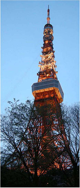
(Extended Text Description: Communications Technologies: This slide contains a photo of Tokyo Tower, which is a communications and observation tower located in the Shiba-koen district of Minato, Tokyo, Japan. At 333 meters, it is the second-tallest structure in Japan.)
Slide 30:
Learning Objective #2
Automatic Vehicle Location (AVL) and Computer-Aided Dispatch (CAD)
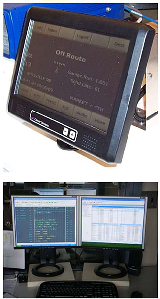
- For operations management - periodically receives real-time updates on vehicle locations and schedule/route status
- Onboard computer with global positioning system (GPS) and mobile data communications
- Provides decisions support tools used by dispatchers and supervisors, allowing proactive management of operations
- Allows for "single point" logon for all onboard systems
Slide 31:
Learning Objective #2
Automatic Passenger Counters (APCs)
- Monitors passenger activity by counting number of boarding and alighting passengers
- Data can either be stored for downloading/uploading or transmitted in real-time
- Most common type is infrared technology
- Ability to "stamp" data with exact bus stop location and time of day through integration with AVL
- Real-time information used for conditional TSP
- Can reduce cost of manual data collection and National Transit Database reporting requirements
-
Agencies typically deploy APC equipment on either:
- 12-25% of their vehicles and then rotate the vehicles on different routes as needed; or
- All vehicles, especially when new buses are purchased
Slide 32:
Learning Objective #2
Scheduling Software

(Extended Text Description: Scheduling Software: This figure shows the scheduling process for fixed-route transit service. The top row of the diagram represents Inputs, the bottom row represents Outputs. Beginning at the top left, a blue rectangle labeled "Service Configurations" lists the following inputs: Route Structure, Span of Service, Service Frequencies, Time Points, and Terminal Points. An arrow points to an output box labeled "Trip Building" with an output of "Time Tables that consider: Cycle Times, No. of Vehicles required, Running Times, Timed Transfers, Layover Recovery Time, Layover Locations, and Interlining." From the "Trip Building" box, an arrow points to a red box labeled "Blocking." Inputs required for "Blocking" appear in a red box above, and include the following work rules concerning: Layover/Recovery Time, Interlining, and Deadhead Time. The "Blocking" outputs listed in the bottom rectangle are "Blocking Sheets that include: Block Numbers, Pull-out/Pull-in Times, Trip Numbers, Terminal Departure and Arrival Times, and Layover/Recovery Time." Also listed is "Block Summary Recap" with "Platform Hours" listed underneath, and "Blocking Graphs." From the "Blocking" box, an arrow points to a box labeled "Runcutting." The inputs in the box above this area address the need for "Work Rules concerning: Min & Max Platform Hours, Report & Turn in Allowances, Spread Time and Penalty, Relief Points & Allowance, Make-up Allowance, and Run Type Percentages." The output listed in the "Runcutting" box below is a "Run Guide that includes: Block Assignments, Pull-out/Pull-in times, Time On and Off Bus, Platform Hours, Total Spread Time, Report Allowance, Turn-in Allowance, Relief Allowance, Make-up allowance, Work Hours, Overtime, Spread Penalty, and Pay Hours." From the "Runcutting" box an arrow points to a yellow box labeled "Rostering." The inputs for "Rostering" that are noted above include work rules concerning the following: Type – Agency Developed vs. Cafeteria Style, Min Work Hours/week, Max Work Hours/ Day, Days Off/Week, Extra Board Procedures, Seniority Lists. The "Rostering" output noted in the lower box includes an Operator Schedule that addresses: Run number, Daily and Weekly Pay Hours, Days Off, Weekdays, Saturday, and Sunday Schedules.)
Slide 33:
Learning Objective #2
Transfer Connection Protection (TCP)
- Triggered when vehicle operator of incoming vehicle makes transfer request using on-board mobile data terminal (MDT) to enter outgoing route
- Central system determines whether outgoing vehicle can and should be held based on estimated arrival time of incoming vehicle
-
Central system will notify:
- Incoming vehicle’s operator whether outgoing vehicle will be held
- Outgoing vehicle’s operator if it is to hold, until what time, and for what route
- Dispatcher reviews current pending transfers
- Will have expanded functionality within an application of Integrated Dynamic Transit Operations (IDTO) bundle of applications within USDOT Connected Vehicle Program
Slide 34:
Learning Objective #2
Transit Signal Priority (TSP)
-
Give authorized transit vehicles ability to automatically change the timing of traffic signals using these strategies:
- Passive Priority
- Active Priority
- Operating in Real-Time
- Can be limited to extending green cycle, but can result in red cycle truncation and phase insertion
- May be done "conditionally" based on passenger load, type of service (Bus Rapid Transit (BRT) vs. local) and schedule adherence
Slide 35:
Learning Objective #2
Transit Signal Priority (TSP) (cont.)
-
Interaction of four major elements:
- Transit vehicle
- Transit fleet management
- Traffic control
- Traffic control management
- Enhanced with four functional applications of vehicle detection, priority request generation (PRG), priority request server (PRS), and TSP control
Slide 36:
Learning Objective #2
Yard Management
- Automatically locates vehicles within certain distance accuracy inside yard
- Allows yard attendants to adjust vehicle locations manually on a yard map
- Provides interface with CAD/AVL system to record pull-in and pull-out time, and assigned vehicle operators
- Can be interfaced with fixed-route scheduling software to access vehicle operator information in real-time
Slide 37:
Learning Objective #2
Intelligent Vehicle Technologies
- Rear Impact Collision Warning System
- Side Collision Warning/Object Detection System (aka Lane Change and Merge Collision Avoidance)
- Frontal Collision Warning System
- Intersection Conflict Warning System
- Lane Change/Merge Warning System
- Pedestrian Collision Warning
Slide 38:
Learning Objective #2
Intelligent Vehicle Technologies (cont.)
-
Vehicle Assist and Automation (VAA):
- Lateral Guidance (aka lane keeping for operating on narrow rights-of-way, such as freeway shoulders)
- Vehicle Platooning
- Precision Docking
- Automated Operations

(Extended Text Description: Intelligent Vehicle Technologies: This graphic contains two photographs. The first photograph shows an example of a Vehicle Assist and Automation tool. The picture shows the front left wheel of a bus. To the left of the bus is a gray curb. Attached to the bus just in front of the wheel is a small wheel installed sideways so that the rotating portion of the little wheel extends beyond the normal width of the bus. The second is a photograph looking down a city street at curb level. On the left is a gray curb. To the right of the curb, there is a light blue line running along the bus lane. Additional Author notes: Vehicle Assist and Automation (VAA) for transit operations assists or automates movement of buses to allow precise operations in extremely narrow lanes, at stations, and potentially bus maintenance facilities.)
Slide 39:
Learning Objective #2
Lane Control Technologies
- Bus shoulder riding
-
Intermittent bus lane (IBL)/moving bus lane (MBL)
- Restricted lane for short time intended to be activated only when flow of general traffic is operating below speed that inhibits bus transit speeds
- When traffic conditions are not expected to cause delays to bus, intermittent bus lanes are not activated
- AVL required to establish bus location ties into variable message signs (VMS) to inform drivers of lane restriction and integration into real-time ITS traffic monitoring systems
Slide 40:

Slide 41:
Learning Objective #2
Which one of these technologies are included in the fleet operations and management category?
Answer Choices
- On-board automated voice announcements
- Scheduling software
- Data management and reporting
- All of the above
Slide 42:
Learning Objective #2
Review of Answers
 a) On-board automated voice announcements
Incorrect. This technology is not included in any of the four categories in the taxonomy.
 b) Scheduling software
Correct! This technology is included in the Fleet Operations and Management category.
 c) Data management and reporting
Incorrect. This technology is included in the Data Management category.
 d) All of the above
Incorrect. These technologies are included in multiple categories in the taxonomy.
Slide 43:
Learning Objective #2
Safety and Security
- Mobile (On Board and Exterior) and Fixed Video Surveillance
- Covert Emergency Alarm and Covert Live Audio Monitoring
- On-board Digital Video Recorders (DVRs)
- G-force Monitoring
Slide 44:
Learning Objective #2
Mobile (onboard and exterior) and Fixed Video Surveillance
- Review recorded images
- Potential crime prevention
- Identify criminal activity and perpetrator(s)
- Identify improper passenger and driver behavior
- Incident/insurance investigation
Slide 45:
Learning Objective #2
Covert Emergency Alarm and Covert Live Audio Monitoring
- Allows dispatchers to listen in on what is happening inside vehicle while an incident is taking place
- Covert microphones are one-way communications in order not to alert person responsible for incident that dispatcher/police are listening in
- Driver in distress presses a covert switch that activates the covert microphone and monitor in dispatcher’s office automatically displays the information for that vehicle and map display zooms in on that vehicle
Slide 46:
Learning Objective #2
Onboard Digital Video Recorders (DVRs)
- Connected to onboard cameras to record images from cameras
- Equipped with removable recording drive to allow playback of recorded video on centrally located playback system
- Able to store specific number of days of video, beyond which, previously recorded video will be overwritten
- May have capability to use Wi-Fi to upload video once vehicle enters yard or garage
Slide 47:
Learning Objective #2
G-Force Monitoring
- System includes g-force sensor and electronic data logger to capture and provide information about unusual movement of transit vehicles and capture events such as vehicle turns, hard braking, and fast acceleration or deceleration
-
G-force data can:
- Assist in accident reconstruction and analysis
- Protect transit agencies from litigation
- Reduce cost of insurance
- Analyze operator actions
- Identify maintenance issues
Slide 48:

Slide 49:
Learning Objective #2
Which of these technologies are in the safety and security category?
Answer Choices
- G-force monitoring
- Data management
- Geographic information systems
- Traveler information
Slide 50:
Learning Objective #2
Review of Answers
 a) G-force monitoring
Correct! This technology is included in the Safety and Security category.
 b) Data management
Incorrect. This is one of the categories and not included in the Safety and Security category.
 c) Geographic information systems
Incorrect. This is included in the Data Management category.
 d) Traveler information
Incorrect. This is not included in any of the four categories in the taxonomy.
Slide 51:
Learning Objective #2
Maintenance
- Engine and drivetrain systems monitoring
- Maintenance software to schedule and track scheduled and unscheduled maintenance activities, and manage parts inventory
- Fuel management system
Slide 52:
Learning Objective #2
Engine and Drivetrain Systems Monitoring (a.k.a. vehicle component monitoring)
- Sensors that monitor various components of vehicle and report back on components performance
- Maintenance supervisors can use this information to perform preventive maintenance intervention before a minor problem becomes major and costly one
- Monitoring performed in real-time and problems are reported instantly
Slide 53:
Learning Objective #2
Maintenance Software
- Facilitates the scheduling of maintenance activities
- Tracks maintenance actions
- Manages parts inventory
-
Assists with:
- Work order management
- Tire management
- Driver reporting
- Mechanic/ technician tracking
- Purchase order generation
- Customer/ departmental billing
- Use of bar coding and handheld data for parts management and inspections
Slide 54:
Learning Objective #2
Fuel Management System
- Measure and manage use of fuel
-
Employ various methods and technologies to monitor and track:
- Fuel inventories
- Fuel purchases
- Fuel dispensed
- Information stored and reports generated with data to inform management practices
-
Online fuel management provided through use of web portals to provide detailed fueling data, enabling:
- Consumption control
- Cost analysis
- Tax accounting for fuel purchases
Slide 55:
Learning Objective #2
Data Management
- Data management and reporting
- Technology integration
- Geographic information system (GIS) application
- Service coordination facilitated by technology
- Open data for third-party application development
Slide 56:
Learning Objective #2
Data Management and Reporting
- Data generated by public transit ITS components installed in vehicles at central locations or at other locations
- Data typically collected and archived in individual databases
- Once data is archived, used for "after-the-fact" analyses and reporting by different business units within a public transport organization (e.g., planning, operations, customer service)
- Utilize true potential of data by consolidating in central repository to make process of data management, analysis, and reporting more efficient
Slide 57:
Learning Objective #2
Technology Integration
- Opportunities for technologies to be integrated with systems that are external to transit agency, such as a regional traffic management center or an information services provider
- Integration, when implemented from enterprise-wide perspective and regional perspective when appropriate, improves overall usability of technology environment made up of products from different vendors on multiple platforms and data from different systems
- Facilitates "system" of interconnected ITS applications that collectively produce services and advantages far greater than ITS applications could achieve individually and independently
Slide 58:
Learning Objective #2
Geographic Information System (GIS) Application
- Provide database management capabilities for display and editing of geographically referenced entities and underlying attribute data
-
Provide ability to perform analyses of geographic features such as:
- Point databases (bus stops, communications transmitters, customer facilities)
- Lines (streets, bus routes, subway tracks, rights of way)
- Areas (census tracks, census blocks, traffic analysis zones, zip codes)
Slide 59:
Learning Objective #2
Geographic Information System (GIS) Application (cont.)
- Combine ability to accurately map geographically referenced data and to create themes such as employment density by traffic analysis zone or mobility limited persons by block group
- Allow transit agencies to analyze potential effects of adding, removing, or re-routing service
- Used to support trip itinerary planning software, flexible routing and scheduling software required in paratransit industry, and real-time vehicle location components of operations software
- Databases most relevant to transit
Slide 60:
GIS (continued)

(Extended Text Description: Geographic Information System (GIS) Application: This image shows the paratransit origins and destinations in Hyannis, MA. This GIS data could be used to justify the creation of one or more fixed routes that cover most of the paratransit origins and destinations. In this image, a roadmap of the Hyannis area is shown. Origin-destination lines appear in light blue. A thin black line represents the Route system. Hyannis destinations are identified with red asterisks. Hyannis origins are marked with green asterisks. Red asterisks are scattered yet more concentrated in the center right of the map. Green asterisks are equally scattered around the map. A dark blue line indicates the number of Origin-Destination Lines AB. Dark blue lines of varying thickness appear connecting various red and green asterisks around the map. The thickest of the blue lines form a "V" shape pointing to a single red asterisk just right of the center of the image.)
Slide 61:
Learning Objective #2
Service Coordination Facilitated by Technology
- Passengers able to reserve, manage, and track their transportation four local transportation providers
- Customers access center by phone or Internet to make or alter travel plans, then track the vehicles in which they’ll be riding
- Partners connected through computer dispatching software, which communicates with every vehicle by onboard computers
- Callers to center able to receive information on health and human services, and general governmental and educational information
Slide 62:
Learning Objective #2
Open Data for Third-party Application Development
-
Definition:
- Accessible at no more than cost of reproduction without limitations based on user identity or intent
- In a digital, machine readable format for interoperation with other data
- Free of restriction on use or redistribution in its licensing conditions
- As of May 2013, 247 out of 863 U.S. transit agencies have open data
Slide 63:
Open ITS Standards
- Standards made available to general public and developed (or approved) and maintained via collaborative and consensus driven process
- Facilitate interoperability and data exchange among different products or services
- Intended for widespread adoption
- Example: OpenStreetMap
Slide 64:
Learning Objective #2
4D Approach to Data Structure Development
- Demand - the identification and prioritization of stakeholder (various business units within an organization) and external data needs
- Dimension - the identification of archived ITS data elements and their characteristics that are of interest to the stakeholders
- Data - the identification of data sources and determining processes (e.g., extract, transform, and load [ETL] procedures) to consolidate data into central repositories
- Delivery - the design and development of reports, tools, and toolboxes to present data to stakeholders
Slide 65:
Learning Objective #2
Typical Datawarehouse and Datamart Configurations
Main Point: Potential ITS data organization
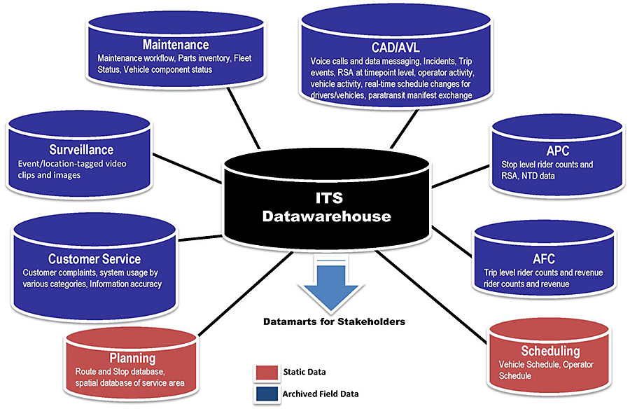
(Extended Text Description: Potential ITS data organization: This is a text graphic demonstrating the relationship of typical datawarehouse and datamart configurations. Items in red are identified as Static Data and items in blue are identified as Archived Field Data, and the entire graphic is labeled Technology Integration. At the center is a black cylinder labeled ITS Datawarehouse with a blue arrow pointing down to the words Datamarts for Stakeholders. Starting at the bottom left and moving clockwise, the following elements surround the central ITS Datawarehouse, and are connected to it with a black line to it from each element. The first (in a red cylinder shape) is Planning: Route and Stop database, spatial database of service area. The second (in a blue cylinder shape) is Customer Service: Customer complaints, system usage by various categories, Information accuracy. The third (blue) is Surveillance: Event/location-tagged video clips and images. The fourth (blue) is Maintenance: Maintenance workflow, Parts inventory, Fleet Status, Vehicle components status. The fifth (blue) is CAD/AVL: Voice calls and data messaging, Incidents, Trip events, RSA at timepoint level, operator activity, vehicle activity, real-time schedule changes for drivers/vehicles, paratransit manifest exchange. The sixth (blue) is APC: Stop level rider counts and RSA, NTD data. The seventh (blue) is AFC: Trip level rider counts and revenue rider counts and revenue. The eighth (red) is Scheduling: Vehicle Schedule, Operator Schedule.)
Slide 66:
Summary of Learning Objective #2
Core Functions and Taxonomy of Transit Management Systems
- Fleet Operations and Management - Ten technologies implemented to facilitate transit operations and provide input to senior management
- Safety and Security - Four technologies improving the safety and security of transit staff and passengers through on-board and facility technologies
- Maintenance - Three technologies facilitate maintenance activities
- Data Management - Five technologies necessary to handle automatically ITS-generated data
Slide 67:
Learning Objective #3: Identify the Relationships and Data Exchange Among Transit Management Systems, Traveler Information, Transit Signal Priority, and Fare Collection Systems
- Fleet Operations and Management - facilitate transit operations and provide input to senior management in terms of system performance
- Safety and Security - improve safety and security of transit staff and passengers
- Maintenance - facilitate maintenance activities such as engine and vehicle component monitoring, tracking of scheduled and unscheduled maintenance activities, inventory systems, and fuel management
- Data Management - data management and reporting, technology integration, geographic information system (GIS) application, service coordination facilitated by technology, and open data for third-party application development
Slide 68:
Learning Objective #3
Fleet Operations and Management
| Category | System/Technology | Dependent on |
|---|---|---|
| Fleet Operations and Management | Communications technologies | Public/private voice and data communication backbones |
| Computer-aided dispatch (CAD) |
Voice and data communications technologies Automatic vehicle location (AVL) system Route and vehicle schedule data |
|
| Automatic vehicle location (AVL) |
Data communications technologies Global positioning system (GPS) or other location enabling technologies, such as WiFi |
|
| Automatic passenger counters (APCs) |
AVL system Route and vehicle schedule data |
|
| Scheduling (fixed-route and paratransit) systems | Stop database (contains data such as stop name, location, routes that stop at this stop, direction of travel from this stop, list of amenities available at this stop) |
Slide 69:
Learning Objective #3
Fleet Operations and Management (cont.)
| Category | System/Technology | Dependent on |
|---|---|---|
| Fleet Operations and Management | Transfer connection protection (TCP) |
AVL system CAD system |
| Transit signal priority (TSP) |
AVL system CAD system (when TSP used based on schedule adherence status) Roadside signal infrastructure |
|
| Yard management | Indoor positioning systems (e.g., radio frequency identification [RFID]-based, WiFi-based) | |
| Intelligent vehicle technologies (e.g., collision warning and precision docking) | Varies by technology application and deployment | |
| Lane control technologies |
AVL system CAD Virtual mirror Lane guidance systems Roadside signal infrastructure |
Slide 70:
Learning Objective #3
Example of Central System Technology Relationships
Main Point: Shows the relationships among central Transit Management and other transit ITS technologies.

(Extended Text Description: Example of Central System Technology Relationships: This graphic shows the relationships among various Central System Technologies. Beginning in the center of the graphic, there is a red rectangular column representing the Central Server Configuration. In this column the following servers are represented in individual blocks from top to bottom: Database Server, CAD/AVL (Computer Aided Dispatch and Automatic Vehicle Location) Server, APC/ASA Mgmt. Server, Fixed Route Scheduling Server, TSP Server, IVR Server, Communications Server, and RTIS/Web Server. From the IVR Server, there is a gray line representing a wired connection that leads to a black box labeled "Central Phone System" with a smart phone icon above it. From the RTIS/Web Server, a red line representing data feed points down to a blue box labeled "Transit Agency Website." Coming from the left side of the RTIS/Web Server is another line pointing to blue box labeled "Third Party Developers." From the left side of the Communications Server, there is a dotted gray line that goes to a black box labeled "Comm Gateway" and branches upwards through three cloud networks (bottom to top: the Wi-Fi/Internet, Cellular Network, and Radio systems), going on to two separate yellow boxes. These boxes are labeled "Revenue Fleet" and "Non-revenue Fleet." From the Cellular network cloud, there is another dotted gray line going downwards representing the wireless connection to the Wayside DMS. Coming from the entire Central Server Configuration, there is a solid green line representing the LAN/WAN connection or VPN. This line goes through a light green box labeled "Transit Agency WAN and LAN" and branches out to a light blue section identified as the "Agency Configuration." Within the "Agency Configuration," the following items are represented in individual dark blue boxes (top to bottom): Electronic Payment System, Maintenance Management System, Video Playback Software, WLAN Download Manager, Workstations to access central systems, VCM Software, and TSP System. Outside the "Agency Configuration," the LAN/WAN connection also leads to a dark blue box labeled as "Future Systems.")
Slide 71:
Learning Objective #3
Example of Onboard Technology Relationships
Main Point: Shows the relationships among on-board Transit Management technologies.
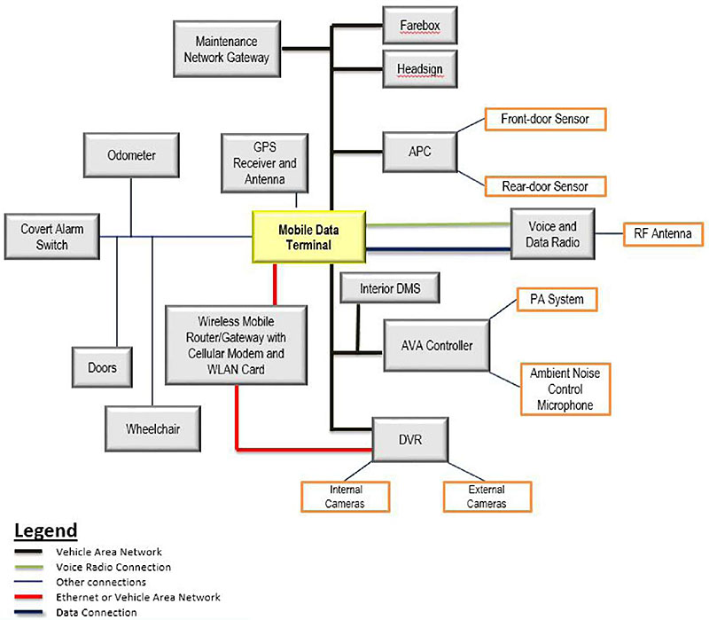
(Extended Text Description: Example of Onboard Technology Relationships: This graphic shows an example of the relationships among various ITS technologies onboard a vehicle. In the center of the diagram is a box labeled MDT (Mobile Data Terminal). Coming from the top of MDT, is a box labeled "GPS Receiver and Antenna" connected via a voice radio connection. Connected to the MDT via a vehicle area network are the Maintenance Network Gateway, farebox, headsign and APC. The APC is connected to the front-door sensor and rear-door sensor via an alternative link. Utilizing both a Voice Radio Connection and a Data Connection, the MDT is connected to the Voice and Data Radio. This is then connected to the RF antenna. Connected by another vehicle area network are the Interior DMS, the ASA Controller, and the DVR. The ASA controller is then connected to the PA system and Ambient Noise Control Microphone. The DVR is connected to internal and external cameras. Coming from the bottom of the MDT rectangle is a red line representing an Ethernet link. This link connects a Wireless Mobile Router/Gateway with cellular modem and WLAN card. This link continues and also connects to the DVR. To the left, the MDT is also connected to the following: Collision Avoidance, Odometer, Covert Alarm Switch, Doors, and Wheelchair.)
Slide 72:

Slide 73:
Learning Objective #3
Computer-aided dispatch (CAD) is dependent upon which one of these technologies?
Answer Choices
- Voice and data communications technologies
- Automatic vehicle location (AVL) system
- Route and vehicle schedule data
- All of the above
Slide 74:
Learning Objective #3
Review of Answers
 a) Voice and data communications technologies
Incorrect. CAD is dependent on voice and data communications.
 b) Automatic vehicle location (AVL) system
Incorrect. CAD is dependent on AVL.
 c) Route and vehicle schedule data
Incorrect. CAD is dependent on route and vehicle schedule data.
 d) All of these
Correct! CAD is dependent on all of these.
Slide 75:
Learning Objective #3
Safety and Security
| Category | System/Technology | Dependent on |
|---|---|---|
| Safety and Security | Fixed video surveillance | Data communications technologies |
| Covert emergency alarm and covert live audio monitoring |
Voice and data communication technologies CAD system AVL system |
|
| On-board digital video surveillance | No dependence on other systems | |
| G-force monitoring | AVL system |
Slide 76:
Learning Objective #3
Maintenance
| Category | System/Technology | Dependent on |
|---|---|---|
| Maintenance | Engine and drivetrain systems monitoring | OBD-II or Society of Automotive Engineers (SAE) J1708/J1939 compatibility of on-board computers within engine and drivetrain |
| Maintenance software to schedule and track scheduled and unscheduled maintenance activities, and manage parts inventory | No dependence on other systems | |
| Fuel Management System | No dependence on other systems |
Slide 77:

Slide 78:
Learning Objective #3
Within the maintenance category, is fuel management dependent on another technology?
Answer Choices
a) Yes
b) No
Slide 79:
Learning Objective #3
Review of Answers
 a) Yes
Incorrect. Fuel Management is not dependent on another technology.
 b) No
b) No
Correct! Fuel Management is not dependent on another technology.
Slide 80:
Learning Objective #3
Data Management
| Category | System/Technology | Dependent on |
|---|---|---|
| Other | Enterprise database/datawarehouse and reporting |
Open databases Data dictionary |
| Technology integration | Multiple dependencies | |
| Geographic information system (GIS) application | Spatial data recording and management systems | |
| Service coordination facilitated by technology |
CAD/AVL systems shared across participants Voice and data communications technologies |
|
| Open data for third-party application development | Standard format for data such as General Transit Feed Specification (GTFS) and GTFS-real time |
Slide 81:
Summary of Learning Objective #3
Identify the Relationships and Data Exchange Among Transit Management Systems and Other Systems
Examples of dependencies for each Transit Management category:
| Category | System/Technology | Dependent on |
|---|---|---|
| Fleet Operations and Management | Communications technologies | Public/private voice and data communication backbones |
| Automatic vehicle location (AVL) |
Data communications technologies Global positioning system (GPS) or other location enabling technologies, such as WiFi |
|
| Automatic passenger counters (APCs) | AVL system Route and vehicle schedule data | |
| Safety and Security | Fixed video surveillance | Data communications technologies |
| Maintenance | Engine and drivetrain systems monitoring | OBD-II or Society of Automotive Engineers (SAE) J1708/J1939 compatibility of onboard computers within engine and drivetrain |
| Data Management | Enterprise database/ datawarehouse and reporting |
Open databases Data dictionary |
| Open data for third-party application development | Standard format for data such as General Transit Feed Specification (GTFS) and GTFS-real time |
Slide 82:
Learning Objective #4: Explain the Role of Systems Engineering and Standards in Procurement
- Extend case studies to explain the underlying SE process used and why it was used
- Describe Transit Management functions with standards and those without standards
- Discuss impact and importance of using SEP in procurement
Slide 83:
Learning Objective #4
Standards Facilitate Transit Management Relationships
- Standards facilitate relationships among Transit Management functions and among Transit Management and other transit functions
- If standards do not exist, SEP will still facilitate the definition of these relationships
-
First several steps of SEP ensure that relationships among transit management components are defined:
- Concept of Operations
- System Requirements
Slide 84:
Learning Objective #4
Case Studies
| Agencies | Project |
|---|---|
| Chattanooga Area Regional Transportation Authority (CARTA),Chattanooga, TN |
|
| LYNX, Orlando, FL |
|
| Efficient Deployment of Advanced Public Transportation Systems(EDAPTS) Program |
|
Slide 85:
Learning Objective #4
SEP Vee Model Adapted by CARTA
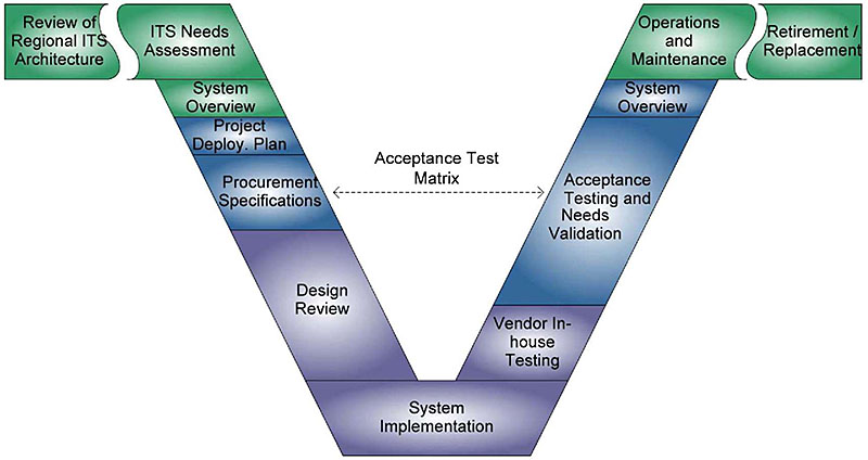
(Extended Text Description: SEP "Vee" model adapted by CARTA: This image contains the "V" diagram from the systems engineering process (SEP) adapted by CARTA. The main graphic of the SEP is the V with some additional horizontal "wings" on the left and right side of the top of the V. The left "wing" of the CARTA V has one step: Review of Regional ITS Architecture. This step is in green, indicating that this activity was conducted for CARTA’s entire ITS Program. At this point, after this step, the steps begin to descend the left side of the V with ITS Needs Assessment (also green in color), System Overview (green in color), Project Deployment Plan, Procurement Specifications and Design Review. The Project Deployment Plan and Procurement Specifications steps are blue in color, indicating that these activities were conducted very each technology project. The Design Review step is purple in color, indicating that this activity was performed primarily by project implementation contractors in a collaborative approach involving CARTA review and feedback. The System Implementation step (purple in color) is at the bottom of CARTA’s V. At this point the steps begin to ascend the right side of the V with Vendor In-house Testing (purple in color), Acceptance Testing and Needs Validation (blue in color), System Overview (blue in color), and Operations and Maintenance (green in color). At this point the step on the right "wing" of the V is Retirement/Replacement (green in color). In CARTA’s V, there is a horizontal dashed line between the Procurement Specifications step on the left, descending side of the V and the Acceptance Testing and Needs Validation.)
Slide 86:
Learning Objective #4
CARTA’s Approach to Applying SEP
- Helped explore and define an overall technology program vision
- Defined ongoing and near-term procurement packages as well as medium- and long-term plans = ConOps
- Developed project deployment plan for each procurement
- Included requirements in procurement as well as acceptance matrix that was basis for later SEP steps
- Vendor completed collaborative design documentation and review process
- Consultant responsible for in-house testing prior to the start of formal acceptance testing
- Testing followed procedures collaboratively planned in advance to verify all acceptance matrix requirements
Slide 87:
Learning Objective #4
CARTA’s Keys to Success
- Using standards in the procurement -SAE J1939 for monitoring common engine, transmission, and braking faults
- Documenting long-term vision for technology
- Avoiding temptation to do too much too fast
- Being willing to accept schedule delays when needed to help manage deployment risks
- Using a data warehouse
- Testing systems thoroughly before introducing them to operations
Slide 88:
Learning Objective #4
LYNX Model Orlando Regionally Efficient Travel Management Coordination Center (MORETMCC) SEP
- Problem: What are you trying to solve?
- Concept: How do you think you will solve the problem? Who are the stakeholders?
- Needs: What do the stakeholders need the solution to do?
- Requirements: How must the solution perform to meet the needs?
- Design: Incorporate the problem statement, concept, needs, and requirements.
Slide 89:
Learning Objective #4
MORETMCC Vision
Main Point: The strategic needs of the TMCC look at the overall TMCC vision from the following four touch points: Customer, Agency, Center of Strategic Operations and Vehicle.
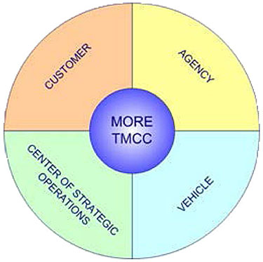
(Extended Text Description: MORETMCC Vision: The graphic in this slide is a circle divided into four sectors, each labeled Customer, Agency, Center of Strategic Operations and Vehicle. In the center of the circle is another smaller circle labeled MORE TMCC. This slide shows how LYNX approached the beginning of the systems engineering process to develop MORETMCC. The strategic needs of the TMCC look at the overall TMCC vision from the following four touch points: Customer, Agency, Center of Strategic Operations and Vehicle.)
Slide 90:
Learning Objective #4
Efficient Deployment of Advanced Public Transportation Systems (EDAPTS)
-
EDAPTS offers:
- Simple Systems Engineering Methodology
- Needs Identification Guidelines
- Procurement Tools
- EDAPTS Research Reports
-
Simplified Systems Engineering Methodology
- Assumes Commercial Off-The-Shelf (COTS)
- Modified FHWA/FTA V-Model
- Used Transit Communications Interface Profiles (TCIP)
- Builds On Operations Guidelines
- Operational Scenarios
Slide 91:
Learning Objective #4
Efficient Deployment of Advanced Public Transportation Systems (EDAPTS) (cont.)
-
Needs Identification Guidelines
- Stakeholders
- Outcomes
- Scenarios
- Priorities
- Operational Scenarios
Slide 92:
Learning Objective #4
EDAPTS SEP and Adaptation of the Vee Model
Main Point: Shows how EDAPTS used the systems engineering process.
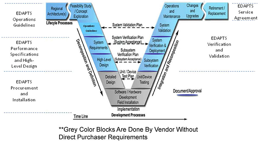
(Extended Text Description: EDAPTS SEP and adaptation of the V model: This image contains the "V" diagram from the systems engineering process. The main graphic of the SEP is the V with some additional horizontal "wings" on the left and right side of the top of the V. Starting from the left "wing" the step is Regional Architecture(s). At this point the steps begin to descend the left side of the V with Feasibility Study/Concept Exploration, Operations Guidelines, System Requirements, High-level Design and Detailed Design. At the bottom of the V is the Software/Hardware Development and Field Installation step. At this point the steps begin to ascend the right side of the V with Unit/Device Testing, Subsystem Verification, System Verification and Deployment, System Validation, and Operations and Maintenance. At this point the steps on the right "wing" of the V are Changes and Upgrades, and Retirement/Replacement. These SEP steps correspond to EDAPTS phases as follows:
- EDAPTS Operations Guidelines consists of the Regional Architecture(s), Feasibility Study/Concept Exploration and Operations Guidelines steps
- EDAPTS Performance Specifications and High-Level Design consists of System Requirements and High-Level Design steps
- EDAPTS Procurement and Installation consists of Detailed Design, Software/Hardware Development and Field Installation, and Unit/Device Testing steps
- EDAPTS Verification and Validation consists of Subsystem Verification, System Verification and Deployment, and System Validation steps
- EDAPTS Service Agreement consists of Operations and Maintenance, Changes and Upgrades, and Retirement/Replacement steps
Slide 93:

Slide 94:
Learning Objective #4
Does EDAPTS assume Commercial-off-the-Shelf (COTS) using a simplified SEP?
Answer Choices
a) Yes
b) No
Slide 95:
Learning Objective #4
Review of Answers
 a) Yes
Correct! EDAPTS assumes Commercial-off-the-Shelf (COTS) using a simplified SEP.
 b) No
b) No
Incorrect. EDAPTS does assume Commercial-off-the-Shelf (COTS) using a simplified SEP.
Slide 96:
Learning Objective #4
Transit Management Functions with Standards
-
Standards in several Transit Management functions, primarily within:
- Fleet Operations and Management
- Data Management
-
Serial Control and Communications Heavy Duty Vehicle Network
-
Related Standards:
- SAE J1708
- SAE J1939
- SAE J1587
- SAE J1944
-
Related Standards:
Slide 97:
Learning Objective #4
Transit Management Functions with Standards (cont.)
- Transit Communications Interface Profiles (TCIP) - two modules on this
- General Transit Feed Specification (GTFS)
- General Transit Feed Specification (GTFS)-realtime
- TransXChange
Slide 98:

Slide 99:
Learning Objective #4
Which one of these standards is used for CAD/AVL systems?
Answer Choices
- GTFS
- SAE J1939
- TransXChange
- All of the above
Slide 100:
Learning Objective #4
Review of Answers
 a) GTFS
Incorrect. GTFS defines a common format for public transportation schedules and associated geographic information.
 b) SAE J1939
Correct! This standard is the vehicle bus used for communication and diagnostics among vehicle components, including CAD/AVL.
 c) TransXChange
Incorrect. TransXChange is the UK nationwide standard for exchanging bus schedules and related data.
 d) All of the above
Incorrect. These standards and formats are used for different purposes - not just for CAD/AVL.
Slide 101:
Learning Objective #4
Impact and Importance of Using SEP in Procurement
-
Allows You To:
- Define and manage system requirements
- Identify and minimize risk
- Integrate system components (physical and organizational)
- Manage system complexity
- Enhance communication and system understanding
- Verify products and services meet customer needs
- Enables Business Planning
- Improves Project Cost Performance
Slide 102:
Learning Objective #4
Impact and Importance of Using SEP in Procurement (cont.)
Main Point: Shows where procurements happen within the SEP.
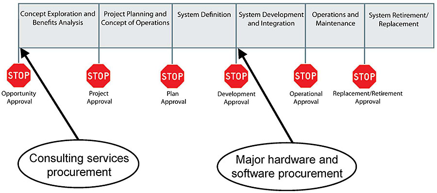
(Extended Text Description: Impact and Importance of Using SEP in Procurement: There are six rectangles side-by-side in this graphic. From left to right, the rectangles are labeled "Concept Exploration and Benefits Analysis," "Project Planning and Concept of Operations," "System Definition," "System Development and Integration," "Operations and Maintenance" and "System Retirement/Replacement." Beneath the left-hand side of "Concept Exploration and Benefits Analysis" is a stop sign that is labeled Opportunity Approval. Beneath the left-hand side of "Project Planning and Concept of Operations" is a stop sign that is labeled Project Approval. Beneath the left-hand side of "System Definition" is a stop sign that is labeled Plan Approval. Beneath the left-hand side of "System Development and Integration" is a stop sign that is labeled Development Approval. Beneath the left-hand side of "Operations and Maintenance" is a stop sign that is labeled Operational Approval. Beneath the left-hand side of "System Retirement/Replacement" is a stop sign that is labeled Replacement/Retirement Approval. There is an oval labeled "Consulting services procurement" beneath the Concept Exploration and Benefits Analysis box. There is a line with an arrow between the Consulting services procurement oval and the lower left-hand corner of the Concept Exploration and Benefits Analysis box. There is an oval labeled "Major hardware and software procurement" beneath the System Development and Integration box. There is a line with an arrow between the Major hardware and software procurement oval and the lower left-hand corner of the System Development and Integration box.)
Slide 103:
Learning Objective #4
Ask Yourself These Questions Before You Begin a Project, and Repeatedly Ask Them Throughout the SE Process
- How well did the system satisfy the needs of the stakeholders?
- Did the project stay within the budgeted cost and schedule?
- What types of challenges occurred during technology implementation?
Slide 104:
Summary of Learning Objective #4
Explain the Role of Systems Engineering and Standards in Procurement
-
Case studies to explain the underlying SEP used and why it was used:
- CARTA
- LYNX
- EDAPTS
-
Transit Management functions with standards:
- Fleet Operations and Management
- Data Management
Slide 105:
Summary of Learning Objective #4 (cont.)
Explain the Role of Systems Engineering and Standards in Procurement
-
Impact and importance of using SEP in procurement:
-
Intended to be integrating mechanism for balanced solutions addressing:
- Capability needs
- Design considerations
- Constraints
-
Intended to address limitations imposed by:
- Technology
- Budget
- Schedule
-
Intended to be integrating mechanism for balanced solutions addressing:
Slide 106:
What We Have Learned
- The National ITS Architecture allows for tailoring at the local level.
- User services represent what the system will do from the perspective of the user.
-
There are four major categories of Transit Management Technologies in the taxonomy
- Fleet Operations and Management
- Safety and Security
- Maintenance
- Data Management
- APCs are dependent on AVL and route and vehicle schedule data.
- CARTA tailored the SEP approach to better suit the scale of their organization and the incremental approach used to develop the overall technology program.
Slide 107:
Resources
- National ITS Architecture 7.0: http://https://www.arc-it.net/
- ITS ePrimer Module 7: Public Transportation: eprimer/module7.aspx
- Systems Engineering for Intelligent Transportation Systems: https://ops.fhwa.dot.gov/publications/seitsguide/section3.htm
- Carol L. Schweiger*and Santosh Mishra, "Utilizing Archived ITS Data: Opportunities for Public Transport," 19th ITS World Congress, Vienna, Austria, 22/26 October 2012, Paper Number AM-00078
- Haas, E. Perry, and J. Rephlo, A Case Study on Applying the Systems Engineering Approach: Best Practices and Lessons Learned from the Chattanooga SmartBus Project, prepared for United States Department of Transportation, Intelligent Transportation Systems Joint Program Office and Federal Transit Administration, submitted by Science Applications International Corporation, November 2009, Contract No.: DTFH61-02-C-00061 Task No.: 61027, http://ntl.bts.gov/lib/32000/32600/32672/61027 se.pdf- content is no longer available.
Slide 108:
Resources (cont.)
- NTI course, Systems Engineering for Technology Projects
- ITS PCB T3 Webinars on ITS Transit Standards, t3_archives.aspx, which includes 14 archived webinars about Transit Management
- EDAPTS: https://dot.ca.gov/programs/research-innovation-system-information
- Doug Jamison and Bill Hearndon, "MORETMCC: Building ITS Capabilities, One Step at a Time," National Rural ITS Conference, Coeur d’Alene, ID, August 31, 2011, http://www.nritsconference.org/downloads/Presentations11/SessionHST Jamison.pdf- content is no longer available.
Slide 109:
Next Course Module
Module 5:
Transit Management Standards, Part 2 of 2
Thank you for completing this module.
Click here to open the feedback form Please provide us your feedback: