← Table of Contents
CAVe-in-a-box – Acceptance Checklist
All the antennas and devices firmly fastened to the box
☐ RSU
☐ OBU
☐ Wired Network Switch
☐ Wi-Fi Switch
☐ Traffic Signal Controller
☐ V2X Hub
☐ Tablet PC
☐ RSU antenna
☐ OBU antenna
☐ Able to power ON all components with one switch
☐ LED/Light turns to the color indicating operating mode depending on the vendors
☐ RSU LED
☐ OBU LED
☐ Wired Network Switch LED flickering green
☐ Wi-Fi Switch LED green
☐ Traffic Signal Controller LCD screen
☐ V2X Hub
☐ Tablet PC
Network scan test [cave-in-a-box.sh from https://github.com/usdot-fhwa-stol/cav-education]
☐ Do all the devices have correct IP/Port combination? If No,
Which devices have incorrect networking?
☐ RSU
☐ OBU
☐ Wired Network Switch
☐ Wi-Fi Switch
☐ Traffic Signal Controller
☐ V2X Hub
☐ Tablet PC
V2X Hub admin portal using the tablet
☐ Enable SPaT Application
☐ Confirm SPaT message count is incremental and frequency is correct (around 100 which means 100 milliseconds between each SPaT message)
BSM receiving
☐ Able to login to the OBU using the tablet (If applicable)
☐ Run vendor specific commands to enable BSM broadcast
☐ Re-connect with the V2X Hub admin portal and enable MessageReceiver plugin
☐ Confirm BSM count is incremental, and frequency is correct (around 100 which means 100 milliseconds between each SPaT message)
CAVe Test Tool application – optional
☐ Confirm the application is running by going to the http://localhost:8000
☐ Confirm BSM displayed as they are received from the OBU
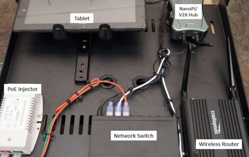
Source: FHWA.
Figure 1. Image. CAVe-in-a-box shelf.
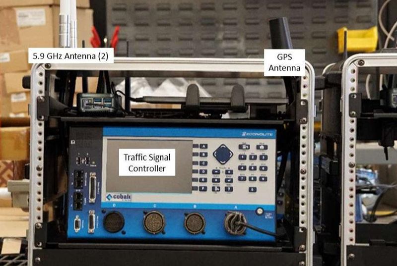
Source: FHWA.
Figure 2. Image. Front view of infrastructure kit.
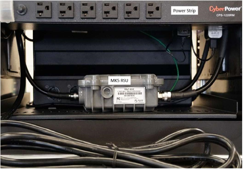
Source: FHWA.
Figure 3. Image. Roadside unit (RSU) in infrastructure kit.
Previous | Next