← Back to Module 13
ITS ePrimer Presentation
Module 13: Connected Vehicles
(Note: This document has been converted from a PowerPoint presentation to 508-compliant HTML. The formatting has been adjusted for 508 compliance, but all the original text content is included, plus additional text descriptions for the images, photos and/or diagrams have been provided below.)
Slide 1:

ITS ePrimer
Module 13: Connected Vehicles
ITS Professional Capacity Building Program
ITS Joint Program Office
U.S. Department of Transportation
Author’s Slide 1 meeting notes below:
This is the title slide. The following slides are in this order:
- Instructor
- Learning Objectives
- Content-related slide(s)
- Summary (what we have learned)
- References
- Questions?
This module is sponsored by the U.S. Department of Transportation’s ITS Professional Capacity Building (PCB) Program. The ITS PCB Program is part of the Research and Innovative Technology Administration’s ITS Joint Program Office.
Thank you for participating and we hope you find this module helpful.
Slide 2:
Instructor
Kyle Garrett
Principal
Synesis Partners LLC
Overland Park, KS, USA
Author’s Slide 2 meeting notes below:
Kyle Garrett is a founding Principal with Synesis Partners and has over forty years of systems engineering and project management experience. In that time he has worked with transportation systems, information technology, wireless commerce, and nuclear power. Kyle and Synesis Partners have provided systems engineering and development in connected and automated vehicle projects for the FHWA Office of Operations, the Saxton Transportation Operations Laboratory, AASHTO, and the Connected Vehicle Pooled Fund Study. He has also been extensively involved with road weather data systems such as FHWA’s Weather Data Environment and its work on Integrated Modeling for Road Condition Prediction. Kyle has degrees in nuclear and mechanical engineering and is a member of the Transportation Research Board Standing Committee on Road Weather.
Slide 3:
Learning Objectives
- Understand the connected ecosystem, including CVs, the connected infrastructure, and communications
- Understand the technological evolution and programmatic history of CVs as they have begun to be deployed within the transportation system, including the roles of government and industry stakeholders
- Understand the benefits and challenges of CV application development and deployment
Author’s Slide 3 meeting notes below:
Module description: This ITS Primer webinar will describe the development and eventual deployment of connected vehicles (CVs) within the surface transportation system with an emphasis on ITS. The module addresses the current and emerging connected ecosystem, technologies, demonstrations, and challenges of deploying infrastructure in support of connected vehicle applications.
Slide 4:
Introduction
Slide 5:
Connecting Vehicles and Infrastructure
- Vehicles have always been connected—only the means of communications have changed
- Traditional traffic communications have been visual
- Hand signals from driver to driver
- Traffic signals
- Pavement markings
- Signs
- Digital wireless communications vastly increase the flow of information
- Vehicle-to-vehicle (V2V)
- Vehicle-to-infrastructure (V2I)
- Vehicle-to-everything (V2X)
Author’s Slide 5 meeting notes below:
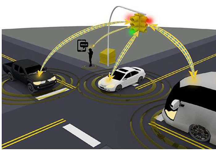
Communications have always been a fundamental means of enabling safety and mobility in transportation. Drivers have received visual information from other drivers, their vehicles, road signs, pavement markings, traffic control devices, and emergency services personnel ever since they appeared on the roadways. The flow of information is now being vastly increased by the availability of digital wireless communications between vehicles, ITS devices, and network services. Vehicle-to-vehicle (V2V), vehicle-to-infrastructure (V2I), vehicle-to-network (V2N) and vehicle-to-everything (V2X) communications are enabling new data exchanges and applications that can increase the safety and mobility performance of the system.
Slide 6:
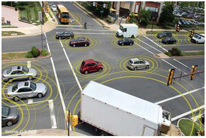
The Connected Vehicle Ecosystem
- A connected vehicle ecosystem enables cooperation among multiple modes and vehicle types as they interact across the road network
- CV ecosystem includes
- Vehicles and travelers
- Passenger
- Commercial
- Transit
- Bicycles and scooters
- Pedestrians
- Infrastructure
- Traffic controls
- Traveler information
- Communications
- Onboard and roadside units
- Message
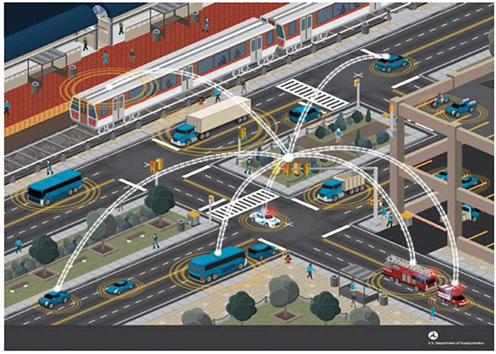
Source: U.S. DOT ITS JPO
Author’s Slide 6 meeting notes below:
Premise of the Connected Vehicle Environment lies in the power of wireless connectivity among vehicles, the infrastructure, and mobile devices to bring about transformative changes in highway safety, mobility, and the environmental impacts of the transportation system.
Connected Vehicles refer to the ability of vehicles of all types to communicate wirelessly with other vehicles and roadway equipment, such as traffic signals, to support a range of safety, mobility, and environmental applications of interest to the public and private sectors. The concept also extends to compatible aftermarket devices brought into vehicles and to pedestrians, motorcycles, cyclists, and transit users carrying compatible devices. Collectively, these components form the Connected Vehicle Environment.
Slide 7:
Benefits of Connectivity
- Crash reductions from increased awareness of events and hazards
- Mobility improvements from travelers having more information on conditions and travel options
- Mobility improvements from operators enabled to act in real time
- Maintenance and operation improvements from improved monitoring and asset allocation
- Environmental impact reductions from better routing and vehicle response to controls
Author’s Slide 7 meeting notes below:
- Crashes can be dramatically reduced when vehicles can sense traffic controls and communicate the events and hazards around them.
- Mobility can be improved when drivers, transit riders, and freight managers have access to up-to-date, accurate, and comprehensive information on travel conditions and options.
- Mobility can be further improved when system operators, including roadway agencies, public transportation providers, and port and terminal operators, have actionable information and the tools to affect the performance of the transportation system in real-time.
- Transportation system management and operations can be enhanced when system operators can continuously monitor the status and direct the various assets under their control.
- Environmental impacts of vehicles and travel can be reduced when travelers can make informed decisions about modes and routes, and when vehicles can communicate with the infrastructure to enhance fuel efficiency by avoiding unnecessary stops.
Slide 8:
CV Benefits
| Impact Area |
Estimated Impacts |
Relevant Applications* |
Program |
| Safety |
Crash population targeted by V2I safety applications at intersections includes up to 575,000 crashes (involving more than 5,100 fatalities) annually** |
PCW, RLVW, SSGA, SSVW |
V2I Safety |
| Safety |
Crash population targeted by V2I safety applications at curves includes up to 169,000 crashes (including 5,000 fatal crashes) annually** |
CSW |
V2I Safety |
| Safety |
Reduction of crashes by up to 25% during winter weather due to weather traffic management applications on freeways*** |
WRTM-VSL |
RWM |
| Safety |
Reduction in speed variations between freeway segments by 18%-58% and within freeway segments by 10%-47%, resulting in fewer rear-end crashes**** |
SPD-HARM |
DMA |
| Safety |
Fewer instances of hard braking and up to 89% reduction in maximum deceleration in incident zones*** |
INC-ZONE |
DMA |
| Mobility |
Reduction in travel time on arterial corridors by 6% to 27% when combined multimodal traffic signal system is implemented*** |
I-SIG, FSP, TSP |
DMA |
| Mobility |
Reduction in travel time for transit vehicles by up to 10% with priority*** |
TSP |
DMA |
| Mobility |
Reduction in travel time by up to 23% and number of stops by up to 15% for emergency vehicles*** |
INC-ZONE |
DMA |
| Mobility |
Reduction in average network-wide delay of up to 14% due to alerts to incident zone workers*** |
INC-ZONE |
DMA |
| Mobility |
Annual travel time reductions of 246,000-740,000 hours when an integrated corridor management decision support system with eco-capabilities is implemented**** |
Eco-ICM |
AERIS |
| Mobility |
Reduction in travel time on freeways by 33% to 42% when cooperative adaptive cruise control, and speed harmonization are optimized for the environment**** |
Eco-Lanes |
AERIS |
| Environmental |
Fuel savings of 2%-22% when signal operations and freeway lane management are optimized for the environment**** |
Eco-Lanes, Eco-Signal Operations |
AERIS |
| Environmental |
Annual fuel savings of 323,000-981,000 gallons when an integrated corridor management decision support system with eco-capabilities is implemented**** |
Eco-ICM |
AERIS |
| Environmental |
Annual mobile emissions savings of 3,100-9,400 tons when an integrated corridor management decision support system with eco-capabilities is implemented**** |
Eco-ICM |
AERIS |
Author’s Slide 8 meeting notes below:
According to the National Highway Traffic Safety Administration (NHTSA), motor vehicle crashes accounted for 33,654 deaths in 2018. The application of connected vehicle technologies is expected to offer significant near-term opportunities for crash reductions. Research conducted by the Volpe National Transportation Systems Center for NHTSA found that deployment of connected vehicle systems and the combined use of V2V and V2I applications have the potential to address 81 percent of unimpaired driver crashes in all vehicle types (i.e., cars and heavy vehicles). A 2015 study for the USDOT ITS Joint Program Office compiled estimates of beneficial impacts shown in the table.
Slide 9:
Historical Context
- 1992 - FHWA Automated Highway System
- 1999 - FCC allocates 75 MHz of spectrum in the 5.9 GHz band for ITS applications
- 2003 - Vehicle Infrastructure Integration (VII) program formed by USDOT, AASHTO, and automakers
- 2006 - VII Concept of Operations published by USDOT
- 2006-09 - VII Proof-of-Concept testing with CAMP in Michigan
- 2011 - VII renamed to Connected Vehicle program; first demonstration of applications at ITS World Congress
- 2011-13 - Testing to determine future of NHTSA Rulemaking
- 2015 - USDOT announces Connected Vehicle Pilot Deployment awards to New York City DOT, the Tampa Hillsborough Expressway Authority, and Wyoming DOT
- 2019-20 - FCC issues notices of proposed rulemaking on allocation of the 5.9 GHz band and use of specific communications technology in that band
Author’s Slide 9 meeting notes below:
In 2003, USDOT, in partnership with other entities including the American Association of State Highway and Transportation Officials (AASHTO) and a number of light-duty vehicle manufacturers, initiated the Vehicle Infrastructure Integration (VII) program to conduct research and move towards deployment.
An initial technical concept for the VII program was comprehensively documented in a Concept of Operations published by USDOT in 2006. This early approach called for vehicles sold in the United States to be equipped with On-Board Equipment (OBE)—a communications device, a positioning device, a processing platform, and application software that would exchange data with Road Side Equipment (RSE), which would be deployed along highways. The OBEs would also be required to communicate with other OBEs for vehicle-to-vehicle data exchange.
USDOT conducted a Proof-of-Concept (POC) test between 2007 and 2009 that proved that the basic technical concept would work.
In 2011, the federal VII program was renamed to the more understood Connected Vehicle program.
From 2011 to 2013, the USDOT ran the Safety Pilot program to collect data to support NHTSA’s rulemaking process
In 2014, the USDOT program, after the success of the safety pilot program, shifted the focus of the Connected Vehicle program towards addressing deployment issues and accelerating deployment.
Slide 10:
CV APPLICATIONS
Slide 11:
CV Application Concepts
- V2I safety applications use infrastructure information to warn drivers of unsafe conditions
- V2V safety applications exchange information among vehicles to warn of potential vehicular conflicts
- Agency applications are focused on system monitoring, planning, and maintenance
- Mobility applications aggregate data from vehicles to facilitate moving around events and enhance movement through the network
- Environmental applications build on the mobility apps to reduce environmental impacts
- Road weather applications use data from vehicles to warn other vehicles of unsafe road conditions
- Smart Roadside applications assist freight operations with infrastructure
Source: USDOT
Author’s Slide 11 meeting notes below:
The Safety Pilot Model Deployment emphasized Vehicle-to- Vehicle Communications for Safety—the wireless exchange of data between nearby vehicles to achieve safety improvements. By exchanging position, speed, and location data, V2V communications enables a vehicle to sense threats and hazards with an awareness of the position of vehicles relative to each other, as well as the threat or hazard they present; calculate risk; issue driver advisories or warnings; or other actions to avoid or mitigate crashes.
The vision for V2V safety applications is that eventually, each vehicle on the roadway (inclusive of automobiles, trucks, buses, motorcoaches, and motorcycles) will be able to communicate with other vehicles and that this rich set of data being communicated will support a new generation of active safety applications and safety systems.
Additional development work is being done by CAMP to address more complex crash scenarios.
Slide 12:
Connected Vehicle Applications
V2I Safety
Red Light Violation Warning
Curve Speed Warning
Stop Sign Gap Assist
Spot Weather Impact Warning
Reduced Speed/Work Zone Warning
Pedestrian in Signalized Crosswalk
Warning (Transit)
V2V Safety
Emergency Electronic Brake Lights (EEBL)
Forward Collision Warning (FCW)
Intersection Movement Assist (IMA)
Left Turn Assist (LTA)
Blind Spot/Lane Change Warning (BSW/LCW)
Do Not Pass Warning (DNPW)
Vehicle Turning Right In Front of Bus Warning (Transit)
Agency Data
Probe-based Pavement Maintenance
Probe-enabled Traffic Monitoring
Vehicle Classification-based Traffic Studies
CV-enabled Turning Movement & Intersection Analysis
CV-enabled Origin-Destination Studies
Work Zone Traveler Information
|
Environment
Eco-Approach and Departure at Signalized Intersections
Eco-Traffic Signal Timing
Eco-Traffic Signal Priority
Connected Eco-Driving
Wireless Inductive/Resonance Charging
Eco-Lanes Management
Eco-Speed Harmonization
Eco-Cooperative Adaptive Cruise Control
Eco-Traveler Information
Eco-Ramp Metering
Low Emissions Zone Management
AFV Charging / Fueling
Information
Eco-Smart Parking
Dynamic Eco-Routing (light vehicle, transit, freight)
Eco-ICM Decision Support System
Road Weather
Motorist Advisories and Warnings (MAW)
Enhanced MDSS
Vehicle Data Translator (VDT)
Weather Response Traffic Information (WxTINFO)
|
Mobility
Advanced Traveler Information System Intelligent Traffic Signal System (l-SIG)
Signal Priority (transit, freight)
Mobile Accessible Pedestrian Signal System (PED-SIG)
Emergency Vehicle Preemption (PREEMPT)
Dynamic Speed Harmonization (SPD-HARM)
Queue Warning (Q-WARN)
Cooperative Adaptive Cruise Control (CACC)
Incident Scene Pre-Arrival Staging Guidance for Emergency Responders (RESP-STG)
Incident Scene Work Zone Alerts for Drivers and Workers (INC-ZONE)
Emergency Communications and Evacuation (EVAC)
Connection Protection (T-CONNECT)
Dynamic Transit Operations (T-DISP)
Dynamic Ridesharing (D-RIDE)
Freight-Specific Dynamic Travel Planning and Performance
Drayage Optimization
Smart Roadside
Wireless Inspection
Smart Truck Parking
|
Source: USDOT
Author’s Slide 12 meeting notes below:
Over the past few years, the USDOT and the transportation industry have made a significant investment in the development of applications in the connected vehicle environment. This development included significant research into identifying and documenting the needs associated with the various stakeholders from which system requirements were developed and prototype applications were built and tested. As part of the Connected Vehicle Pilot program, the USDOT identified a significant number of applications or potential applications for deployment at these sites.
Slide 13:
Example Application - Red Light Violation Warning
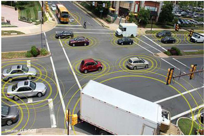
- RLVW is a priority V2I application
- A CV approaching an intersection gets information about the intersection geometry and signal phase and timing (SPaT)
- An on-board app determines from its position and speed whether the vehicle can make it through the intersection without violation
- A warning is issued to the driver if a violation is likely
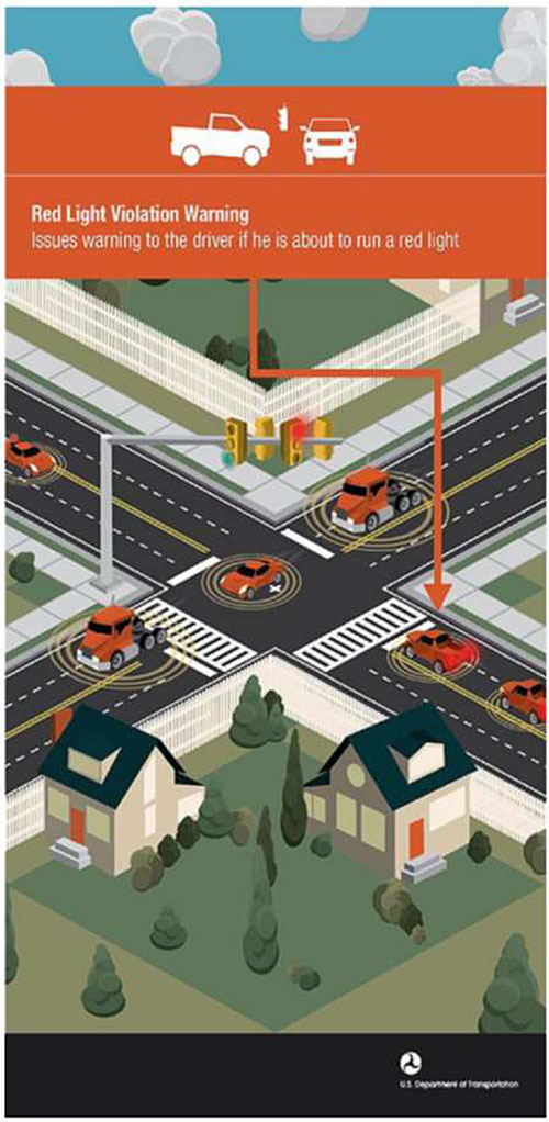
Source: USDOT ITS JPO
Author’s Slide 13 meeting notes below:
Red light violation warning (RLVW) is a priority V2I safety application. It has the potential to reduce the likelihood of serious crashes and can be deployed in all vehicle types.
In the RLVW application, as shown in Figure 2, a CV approaching a connected intersection receives messages describing the intersection geometry, signal phase and timing, and real-time position corrections (if available). The application in the vehicle uses its position, speed, and heading to make a determination relative to intersection geometry and signal timing as to whether it can proceed through the intersection without violating the red signal. A warning is shown to the driver if a violation is likely.
Slide 14:
CV Application Architecture Reference
- National ITS Reference Architecture (now ARC-IT) incorporates connected vehicle applications with the infrastructural ITS architecture
- Four architectural views
- Enterprise
- Functional
- Physical
- Communications
- Architecture components modeled as 48 physical and 372 functional objects
- Back office centers and services such as TMCs and security certificate systems
- Field objects such as traffic signals and CV roadside equipment
- Vehicles and their CV apps
- Personal objects such as user devices (cell phones)
- Communications objects such as vehicle on-board equipment
Author’s Slide 14 meeting notes below:
The National ITS Reference Architecture, now known as the Architecture Reference for Cooperative and Intelligent Transportation (ARC-IT), combines the previous National Intelligent Transportation Systems Architecture and the Connected Vehicle Reference Implementation Architecture (CVRIA). It describes the integration of CV systems with infrastructural ITS in a set of four architectural views: Enterprise, Functional, Physical, and Communications.
- Enterprise - Describes the relationships between organizations and the roles those organizations play within the connected vehicle environment
- Functional - Describes abstract functional elements (processes) and their logical interactions (data flows) that satisfy the system requirements
- Physical - Describes physical objects (systems and devices) and their functional objects as well as the high-level interfaces between those physical objects
- Communications - Describes the layered sets of communications protocols that are required to support communications among the physical objects that participate in the connected vehicle environment
Connected vehicle applications are incorporated among the service packages defined by ARC-IT. https://www.arc-it.net/index.html
Slide 15:
CONNECTED ECOSYSTEM TECHNOLOGIES
Slide 16:
Connected Vehicle Technologies
- Location technology
- GNSS/GPS
- Differential GPS
- Vehicle sensors, e.g.,
- Accelerometers
- Steering angle
- Wheel speed
- Braking
- Headlights
- On-board communications
- Driver-vehicle interface
- Displays/alerting
- Tablet/phone
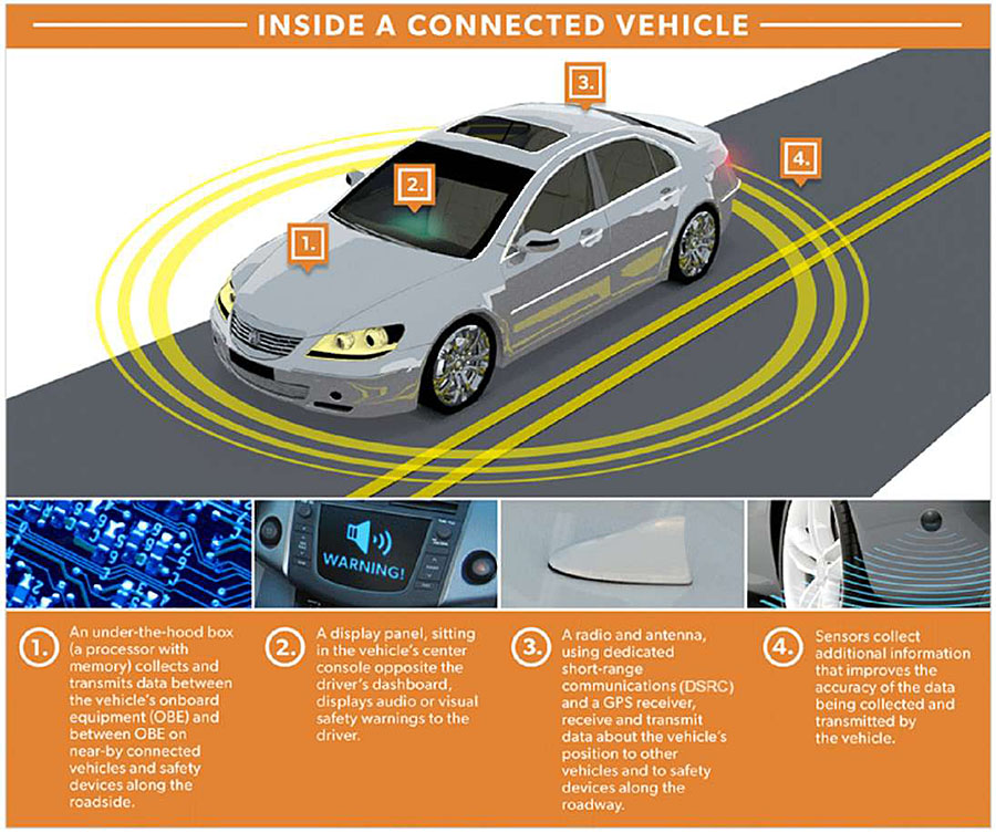
Source: USDOT ITS JPO
Author’s Slide 16 meeting notes below:
Operation and data exchanges among CVs and with infrastructure in a connected ecosystem require both physical and informational technologies to be deployed to the CV. Many of these are common features in modern vehicles, but become essential to CV applications. As shown in the figure, these can be grouped broadly into location technologies, vehicle sensors, on-board equipment for communications, and the driver-vehicle interface features for connected applications.
Determining vehicle location is critical to safety and most mobility applications. Vehicle location and time reference are provided by a global navigation satellite system (GNSS). In the United States, GNSS location services are provided by the Global Positioning System (GPS) operated and maintained by the US Air Force. Positions provided by GPS may be locally corrected by fixed Differential GPS (DGPS) to account for reduced satellite visibility in dense urban canyons or mountainous areas. https://www.gps.gov/
On-board vehicle sensors and controls provide data for use in the vehicle’s own electronic control units, but the data may also be sent and used by CV applications outside the vehicle. Sensors and controls with data valuable to CV applications are generally monitoring the vehicle’s kinematics (speed, acceleration, and direction of travel), the roadway (vertical accelerations and braking effectiveness), or its operating environment (ambient temperature, precipitation, and lighting).
On-board equipment (OBE) provides vehicular access to wireless communications with other vehicles, infrastructure, and networks. An OBE provides access through one or more wireless media and communications spectrum bands. The OBE accesses vehicle data from the controller area network (CAN) bus, packages the data in message formats appropriate to the communication media type, and broadcasts the messages through its antenna. The OBE may also provide processing and data storage for on-board components of CV applications.
Connected vehicle applications may also need a driver-vehicle interface (DVI) for providing advisories and warnings. The DVI may be an aftermarket device such as a tablet that is mounted in the vehicle operator’s view, or may be more fully integrated with the vehicle’s operator displays and controls.
Slide 17:
Connected Infrastructure Technologies
- Roadside ITS technology
- Traffic signal controllers
- Broadcast signal phase and timing
- Map messages
- Support violation and signal priority applications
- Dynamic message signs
- Ramp meters
- Environmental sensor stations
- Support motorist advisories and warnings
Source: USDOT ITS JPO
Author’s Slide 17 meeting notes below:
Communications between vehicles and roadway infrastructure are critical to many CV applications. Connected infrastructure maintains existing ITS functionality to support non-connected vehicles and their drivers, and is expanded to support CV applications and eventually AVs. The connected infrastructure includes field components at the roadside and systems in the back office.
Traffic signal controllers are located at intersections to monitor and control traffic signal operations. These locations are ideally suited for connected infrastructure interactions with passing CVs. As illustrated in the figure, they can process and broadcast traffic operations data, such as SPaT, that can be used in many CV intersection safety and mobility applications.
Other ITS field devices and controllers may be upgraded to support specific CV applications at locations other than intersections. Dynamic message signs (DMS) can be connected to provide local broadcast of traveler information for in-vehicle displays. Ramp metering systems and controllers located along freeway corridors could be enabled to provide in-vehicle metering indications and to support mobility applications.
Environmental sensor stations (ESS) monitor weather and road conditions that are needed for developing motorist advisories and warnings (MAW).
Slide 18:
More Connected Infrastructure Technologies
- Roadside equipment for communications
- RSEs provide the infrastructure interface for V2I messaging
- Radio and antenna
- Processor
- Local and area network interfaces
- Standardized for spectrum and media protocol, supported by a Qualified Product List
- V2X Hub
- Network edge process for data translation between message standards
- Supports, for example, SPaT translation from NTCIP 1202 into SAE J2735
- Center systems and backhaul
- Not required for all CV apps
- Can enable apps to access cloud computing resources and data
- Example ATMS interactions:
- CV probe data in
- Traveler information out
Author’s Slide 18 meeting notes below:
Roadside equipment (RSE) for wireless communications provides the infrastructure interface for V2I communications. Independent of the particular wireless spectrum and media protocols used for the communications, the RSE consists of a radio, antenna, processor, and interfaces to other local devices (generally through a local Ethernet connection). It generally will also interface with an agency or commercial network for backhaul to central ITS services and data.
Data in the connected ecosystem is shared among many components and services, each with its own native data structures and formats. Data translation between these formats is a fundamental need and challenge for CV applications. The V2X Hub is an opensource software package developed by USDOT for CV data translation, aggregation, and dissemination.
Center systems within an ITS architecture will generally be users of CV data from the field and providers of traveler information processed from CV data and other ITS sources.
Slide 19:
Communications and Messaging Standards
- Connected vehicle communications technologies are in transition in 2021
- The FCC in 1999 allocated spectrum in the 5.9 GHz band to be reserved for Dedicated Short-range Communications in support of vehicular safety applications
- The FCC in 2020 issued Notices of Proposed Rule Making (NPRMs) to amend that allocation and indicated intent to:
- Reduce the bandwidth from 75 to 30 MHz
- Replace DSRC with Cellular V2X (C-V2X) technology
- The FCC docket has collected substantial comments on the NPRMs; the matter is in review as of March 2021
- Updated information on 5.9 GHz communications is available on the USDOT Safety Band website and on the FCC online docket resources
- Other wireless communications technologies have and may in the future play roles in CV applications
- More information at the USDOT Safety Band website: https://www.transportation.gov/content/safety-band
Author’s Slide 19 meeting notes below:
Communications put the connectivity in connected vehicles!
USDOT Safety Band website: https://www.transportation.gov/content/safety-band
Although the 1999 FCC spectrum allocation for ITS safety and mobility applications reserved the 5.9 GHz band for DSRC, the use of that band for particular communications technologies is under FCC review as of 2020. Updated information on communications technologies in the 5.9 GHz band may be found on the USDOT’s Safety Band website or Federal Communication Commission online docket resources. Connected vehicle communications are possible and have been demonstrated over a variety of wireless media. The criteria for what media are applicable for a given application. https://www.transportation.gov/content/safety-band
Slide 20:
Dedicated Short Range Communications (DSRC)
- A set of standards and technologies
- A variant of Wi-Fi for wireless access in vehicular environments
- Derived from the IEEE 802.11 standard
- Includes WAVE Short Message protocol defined in IEEE 1609 standard
- Proven technology for low-latency applications
- Data transmitted as often as 10 times per second
- Nominal range of 300 meters
- Privacy built into protocols and standards
Author’s Slide 20 meeting notes below:
DSRC technologies were developed specifically for vehicular communications. In 1999, the Federal Communications Commission (FCC) established standard licensing and service rules for DSRC and allocated 75 MHz of spectrum in the 5.9 GHz band.
DSRC is to be used for the purpose of protecting the safety of the traveling public. DSRC is a communications protocol developed to address the technical issues associated with sending and receiving data among vehicles, and between moving vehicles and fixed roadside access points.
DSRC also includes the Wireless Access in Vehicular Environments (WAVE) Short Message protocol defined in the IEEE 1609 standard that allows terminals to broadcast messages to all other devices in radio range.
The design range of a DSRC access point is about 300 meters, although ranges up to about 1 kilometer have been observed. Typical installations are expected to be at intersections and other roadside locations.
Slide 21:
3G/4G/LTE Cellular Communications
- 3G/4G/LTE cellular communications have been used for applications tolerant of some latency (on the order of seconds)
- Can provide high data rates to a large number of users simultaneously
- Widely available in personal devices and vehicles
- Good coverage - all urban areas and most major highways
- Have proven utility in routing and mobility applications
Author’s Slide 21 meeting notes below:
Beyond the commitment to DSRC for active safety applications, USDOT is exploring all wireless technologies for their applicability to other safety, mobility, and environmental applications. Cellular communications is a candidate for some safety applications, as well as mobility and environmental applications in the Connected Vehicle Environment.
Cellular communications systems are intended to serve mobile users, so they are designed to provide high data bandwidth to users in motion. They are also widely deployed so that users can access the service wherever they go. Generally, all urban areas have cellular coverage provided by multiple carriers. While not ubiquitous, most major highways also have coverage.
The next generation technologies for cellular communications are being designed with higher bandwidth’s and speeds to support new applications and the Internet of Things community. These technologies, including LTE Direct and 5G, have the potential to expand the role of cellular in the future of the CV program (2020 and beyond).
Slide 22:
Cellular V2X (C-V2X)
- C-V2X is an extension to existing cellular technologies (LTE Direct)
- Can add V2X technology to existing cellular devices
- Operates in two modes
- Direct communications for V2X in the 5.9 GHz band
- Cellular connections for V2N over carrier network
- FCC approved for demonstration operations in the 5.9 GHz band
- Provides eventual path for transition to 5G cellular communications
Author’s Slide 22 meeting notes below:
Cellular V2X (C-V2X) is an extension of cellular technology that adds direct V2V and V2I communications to the network modes used by handsets around the world. The V2V and V2I communications are an adaptation of earlier LTE Direct connection technology for vehicular applications. The FCC has approved C-V2X demonstration operations in the 5.9 GHz band alongside DSRC. https://www.qualcomm.com/media/documents/files/introduction-to-c-v2x.pdf
Slide 23:
Messaging Standards
- Messaging standards are critical for ensuring interoperability of applications across technologies and vendors
- Data representations are defined in SAE J2735 message sets, including the following:
- Basic Safety Message (BSM)
- Emergency Vehicle Alert (EVA)
- Map Data (MAP)
- Signal Phase and Timing (SPAT)
- Real-time position correction in a standard Radio Technical Commission for Maritime Services (RCTM) format
- Traveler Information (TIM)
- Performance requirements for specific applications are developed under the SAE J2945 family of standards
- Messaging standards are intended to apply to all technologies used for V2X applications
Author’s Slide 23 meeting notes below:
Basic Safety Message (BSM), for information from a vehicle describing its position, speed, heading, and state. This message is used in many safety applications.
Emergency Vehicle Alert (EVA), for warnings for emergency vehicles operating in the vicinity.
Map Data (MAP), describing intersection, roadway, and curve geometries.
Signal Phase and Timing (SPAT), used in intersection conflict avoidance and mobility applications.
Real-time position correction in a standard Radio Technical Commission for Maritime Services (RCTM) format.
Traveler Information (TIM), providing advisories and road sign information.
Slide 24:
Cyber Security
- Cyber security is a major concern for CV applications and technology
- Must address vehicles, infrastructure, and communications
- Vehicle cyber security focuses on preventing access to vehicle systems and components
- Infrastructure cyber security focuses on protecting against threats to roadside equipment and systems
- V2X communications cyber security focuses on ensuring trust in communications among vehicles and with infrastructure
- Vehicles and infrastructure have security threats and countermeasures independent of CV applications, addressed in other contexts
- V2X communications security is founded on a Security Credential Management System (SCMS)
- Uses a public key infrastructure of encryption and certificate management
- Used digital certificates issued by the SCMS
- Contains no personal or equipment identification
Author’s Slide 24 meeting notes below:
A broad view of cyber security measures in support of CV applications needs to address potential threats to the vehicles, infrastructure, and communications. Each of these has its own challenges based on access, types of potential attacks, and functional vulnerabilities.
Slide 25:
CV INITIATIVES AND PROGRAMS
Slide 26:
USDOT Safety Pilot
- Deployed CV safety technologies, applications, and systems using everyday drivers in the real world from 2011-13 in two components
- Driver Clinics
- Model Deployment
- Driver Clinics
- Safety applications in controlled roadway situations
- Explored everyday driver reactions
- Six sites across the U.S.
- Model Deployment
- Tested concentrated deployment of 2800 vehicles for data interfaces and vehicle interactions
- Test site in Ann Arbor, MI, with mix of cars, trucks, and transit vehicles
Source: USDOT
Author’s Slide 26 meeting notes below:
The Safety Pilot Model Deployment emphasized Vehicle-to- Vehicle Communications for Safety—the wireless exchange of data between nearby vehicles to achieve safety improvements. By exchanging position, speed, and location data, V2V communications enables a vehicle to sense threats and hazards with an awareness of the position of vehicles relative to each other, as well as the threat or hazard they present; calculate risk; issue driver advisories or warnings; or other actions to avoid or mitigate crashes.
The vision for V2V safety applications is that eventually, each vehicle on the roadway (inclusive of automobiles, trucks, buses, motorcoaches, and motorcycles) will be able to communicate with other vehicles and that this rich set of data being communicated will support a new generation of active safety applications and safety systems.
Additional development work is being done by CAMP to address more complex crash scenarios.
Slide 27:
USDOT Connected Vehicle Pilot Program
- USDOT initiative to spur deployment and begin to address ongoing deployment and operational issues
- Proposed projects identified local needs, set performance goals and selected CV applications to meet those goals
Source: USDOT
Author’s Slide 27 meeting notes below:
In 2014, the USDOT focused more on implementation issues associated with the Connected Vehicle program. Past investments in foundational research and the initial development of connected vehicle applications had resulted in many tools that needed to be exercised in a real-world environment. This included the tools to support development of concepts of operations and system requirements and a number of prototype applications. There was a need to couple these investments with an investment in deployment and operations to determine the potential long-term impacts of a connected vehicle deployment.
Slide 28:
USDOT CV Pilot Deployment Program Sites
- Three sites selected for Pilot Deployment in 2015
- New York City - vehicle and pedestrian safety
- Wyoming I-80 Corridor - freight vehicles and weather applications
- Tampa-Hillsborough Expressway - congestion relief and safety
- Three-phase deployment
- 12-month concept development
- 24-month development and site deployment
- Ongoing operations to monitor impacts
- More information at https://www.its.dot.gov/pilots/index.htm
Author’s Slide 28 meeting notes below:
In September of 2015, the USDOT selected the following three pilot sites: New York City, Wyoming, along its I-80 corridor; and Tampa, Florida. Each site spent 12 months developing a deployment concept and 24 months to design, build, and test deployment of the CV technologies described in their concepts. In late 2018, the sites began a third phase of operations for monitoring system impacts against key performance measures. More information on these sites and the lessons learned is being published on a regular basis by USDOT at https://www.its.dot.gov/pilots/index.htm.
Slide 29:
Smart Cities - Columbus
- USDOT launched Smart City Challenge in 2015
- 78 applicant mid-sized cities applied
- 7 finalist cities
- Columbus, Ohio selected
- CV technologies and applications key to Columbus solutions, within larger perspectives and vision for an integrated, first-of-its-kind smart transportation system
- More information at https://www.transportation.gov/smartcity
Author’s Slide 29 meeting notes below:
In December of 2015, USDOT launched its Smart City Challenge, "asking mid-sized cities across America to develop ideas for an integrated, first-of-its-kind smart transportation system that would use data, applications, and technology to help people and goods move more quickly, cheaply, and efficiently. The Challenge generated an overwhelming response: 78 applicant cities shared the challenges they face and ideas for how to tackle them." Seven finalists worked with the DOT to further develop their ideas, and the City of Columbus, Ohio, was selected as the winner. Connected vehicle technologies and applications were key enablers of the Smart Columbus solution.
Slide 30:
CV Pooled Fund Study
- CV Pooled Fund Study (PFS) formed in 2009
- Federal, state, local agencies
- Chartered to aid IOOs and OEMs in justifying and promoting large-scale CV deployments
- Projects in modeling, planning, engineering, and development
- 13 completed projects and four projects underway as of 2020
- V2I Queue Advisory/Warning
- Using Third-Party Data to Deliver V2I
- Multi-modal Intelligent Traffic Signal System - Phase III: Deployment Readiness Enhancements
- Creation of a Guidance Document for MAP Preparation
- More information at https://engineering.virginia.edu
Author’s Slide 30 meeting notes below:
The Connected Vehicle Pooled Fund Study (CV PFS) was formed by Federal, State, local, and international transportation infrastructure owner-operators (IOOs) in 2009, "to aid transportation agencies and OEMs [original equipment manufacturers] in justifying and promoting the largescale deployment of connected vehicle environment and applications through modeling, development, engineering and planning activities." The CV PFS has sponsored research, development, deployment, and evaluation of CV application in 13completed projects and has four projects underway as of 2020.
Slide 31:
Cooperative Automated Transportation (CAT) Coalition
- Collaborative focal point for connected and automated vehicle deployment
- Sponsored by AASHTO, ITS America, and ITE
- Members from among IOOs, OEMs, technology and service providers, and Internet of things (IoT) suppliers
- Seven working groups covering
- Programmatic and strategic activities
- Planning, scenarios, and resources
- Infrastructure and industry
- Numerous studies, initiatives, ad technical resources
- More information at https://transportationops.org/CATCoalition/resources
- SPaT Challenge
- Issued in 2015 to stimulate US IOO V2I infrastructure deployment for SPaT and MAP message broadcasts
- 26 states, 216 intersections operating, 2121 intersections planned as of 2020
- https://transportationops.org/spatchallenge
Author’s Slide 31 meeting notes below:
"The Cooperative Automated Transportation (CAT) Coalition serves as a collaborative focal point for Federal, State and local government officials, academia, industry and their related associations to address critical program and technical issues associated with the nationwide deployment of connected and automated vehicles on streets and highways. Coalition membership includes representation from infrastructure owners and operators (IOOs), OEMs, technology and service providers, and Internet of things (IOT) suppliers." The CAT Coalition is collaboratively sponsored by the American Association of State Highway and Transportation Officials (AASHTO), ITS America, and ITE. https://transportationops.org/CATCoalition
In 2015, the CAT Coalition issued the SPaT Challenge as means of equipping and seeking the commitment of US IOOs to deploy V2I infrastructure with SPaT and MAP message broadcasts in at least one corridor or network—about 20 signalized intersections—in each of the 50 States by 2020. The program also developed informational and technical resources to support these deployment commitments. Applications intending to use SPaT and MAP messages in these deployments include transit and snow plow signal prioritization, red light violation warning, spot weather warnings, and vehicle-to-pedestrian warnings. More information is available at https://transportationops.org/spatchallenge.
Slide 32:
CV Deployments in the U.S.
Source: USDOT
Source: USDOT
https://www.transportation.gov/research-and-technology/interactive-connected-vehicle-deployment-map
Author’s Slide 32 meeting notes below:
The number of CV deployments across the United States has made it difficult to maintain awareness of the variety of applications and technologies being deployed. USDOT has compiled an interactive map and database of CV operational and planned deployments to provide that overview. The Interactive Connected Vehicle Deployment Map tool, available at https://www.transportation.gov/research-and-technology/interactive-connected-vehicle-deployment-map, also provides a state-by-state view of economic costs that might be mitigated in potential CV deployments.
Slide 33:
NCHRP 20-102
Author’s Slide 33 meeting notes below:
The Transportation Research Board (TRB) NCHRP Project 20-102 on Impacts of Connected and Automated Vehicles on State and Local Transportation Agencies has developed a significant body of fundamental research. Its objectives are to identify, conduct, and disseminate findings in CV and AV research for IOOs. Reports produced under this project have addressed topics as varied as business models, data management, planning guidance, and laws and regulations. More information is available at https://apps.trb.org/cmsfeed/TRBNetProjectDisplay.asp?ProjectID=3824.
Slide 34:
Connected Intersections
- CV technology interoperability largely achieved through standards for equipment and software
- Consistent deployment practices will also be needed
- OEM and vehicle owner expect CV applications to be available and operate consistently across the U.S.
- ITE, USDOT, AASHTO, IEEE, SAE, and NEMA are working together on connected intersection standard practices
- Includes stakeholders from
- IOOs
- OEMs
- Fleet operators
- Safety advocacy groups
- Multimodal partners
- More information at https://www.ite.org/technical-resources/standards/connected-intersections/
Author’s Slide 34 meeting notes below:
Connected vehicle technologies have largely achieved interoperability through development and application of standards to equipment and software. Some level of standard practices will also be necessary to achieve a consistent deployment of CV applications and infrastructure across the US. Original equipment manufacturers and vehicle owners will have an expectation that CV applications deployed in those vehicles are broadly and reliably available as they operate around the country. The Institute of Transportation Engineers and partner associations including the USDOT, AASHTO, IEEE, SAE, and the National Electrical Manufacturers Association (NEMA) are developing standards and recommended practices for deployment of connected intersections. Stakeholders from among IOOs, OEMs, fleet operators, safety advocacy groups, multimodal partners, and others are providing perspectives and information to the systems engineering process for these developing connected intersection standards. More information is available at https://www.ite.org/technical-resources/standards/connected-intersections/.
Slide 35:
International Harmonization
- USDOT collaborates internationally with other governments, industry associations, and standards development organizations (SDOs) on deployment of CV applications
- Shared research
- Common hardware and software
- Improved interoperability across borders
- Facilitation of a global marketplace
- Other governments including EU, Australia, Japan, Korea, and Canada
- SDOs
- International Organisation for Standardization (ISO)
- European Telecommunications Standards Institute (ETSI)
- European Committee for Standardization (CEN)
- Domestic SDOs, including IEEE, SAE, AASHTO, and NEMA
Author’s Slide 35 meeting notes below:
Recognizing that development and deployment of CV applications extends across international borders, the USDOT collaborates with other institutions including governments, industry associations, experts, and standards development organizations (SDOs) to support those efforts.
The USDOT maintains important cooperative agreements with other countries in support of harmonization efforts. The Implementing Arrangement with the European Union (EU) has formed the basis of much of the USDOT’s work in international harmonization, and has provided additional means for multilateral efforts with other nations.
USDOT collaborates with multiple SDOs working on ITS and related standards to facilitate harmonization when in the public interest. These relationships fund experts and State and local participants to identify requirements in standards working groups, as appropriate.
Slide 36:
Summary
- The connected ecosystem uses wireless connectivity among vehicles, the infrastructure, and mobile devices to bring about transformative changes in highway safety, mobility, and the environmental impacts of the transportation system
- Requires participation of a broad community of stakeholders: transportation agencies, vehicle manufacturers, telecommunications providers and manufacturers, information service providers, and researchers
- Benefits from the connected ecosystem come from the following:
- Combined use of V2V and V2I communications to address crashes
- Reductions in urban traffic congestion, travel delays, vehicle emissions and fuel consumption
- Seven categories of CV applications
- V2V safety
- V2I safety
- Mobility
- Environmental
- Road Weather
- Agency Data
- Smart Roadside
Author’s Slide 36 meeting notes below:
- The connected ecosystem uses wireless connectivity among vehicles, the infrastructure, and mobile devices to bring about transformative changes in highway safety, mobility, and the environmental impacts of the transportation system.
- The vision of a national multimodal connected ecosystem requires participation of a broad community of the following stakeholders: Federal, state, and local transportation agencies; car, truck and bus manufacturers; telecommunications providers and consumer electronics manufacturers; transportation information service providers; and researchers.
- Benefits from the connected ecosystem are expected to accrue in a number of the following areas:
- Combined use of V2V and V2I communications to address crashes in all vehicle types
- CV systems to reduce urban traffic congestion, travel delays, and vehicle emissions as well as improve vehicle fuel efficiency
- Applications enable the CV systems and technologies to deliver services and benefits to users. Applications are the most visible part of the connected ecosystem.
- Connected vehicle applications are typically divided into the following seven broad categories, with each category comprised of bundles of individual applications:
- V2V safety
- V2I safety
- Mobility
- Environmental
- Road Weather
- Agency Data
- Smart Roadside
Slide 37:
Summary
- Deployment of technologies will include the following:
- Connected vehicles, their sensors, and on-board equipment
- Connected infrastructure
- Communications
- Standards for message exchange and content
- Successful CV application deployment requires collaboration
- Federal, state, and local transportation agencies
- Vehicle manufacturers and technology industries
- Researchers in academia and industry
- Standards development organizations
- Professional and industry associations
- Challenges remain
- Consistent application of cybersecurity practices across the connected ecosystem
- Demonstration of CV application benefits in real-world deployments
- Programmatic planning and investment for CV infrastructure
Author’s Slide 37 meeting notes below:
- The connected ecosystem will require the deployment of technologies on vehicles and across the following infrastructure systems:
- Connected vehicles, their sensors, and on-board equipment for communications and application processing
- Connected infrastructure, in roadside equipment, management centers, and information services
- Communications among all potential user devices, in both low latency local and wide area network connections
- Standards for message exchange and content
- Successful CV application deployment has required collaboration among the connected ecosystem stakeholders including Federal, state, and local transportation agencies; vehicle manufacturers and technology industries; researchers in academia and industry; standards development organizations; and professional and industry associations.
- Strategic challenges remain in development and deployment of CV applications and technology:
- Consistent application of cybersecurity practices across the connected ecosystem
- Demonstration of CV application benefits in real-world deployments
- Programmatic planning and investment for CV infrastructure
Slide 38:
References
Author’s Slide 38 meeting notes below:
Other references related to the development and deployment of connected vehicles and technology are available in the text version of the ePrimer Module 13.
Slide 39:
Questions?
Return to top ↑