skip to main content

← Table of Contents

USDOT’s ISD Message Creation Tool

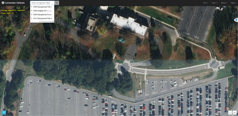
Using the Intersection Situation Data (ISD) Message Creation Tool requires internet access. It is recommended to use the tool on an external computer. Created MAP files will need to be transferred to the V2X Hub computer. Either a USB, ethernet connection, or wireless connection to kit’s router may be used to transfer file.

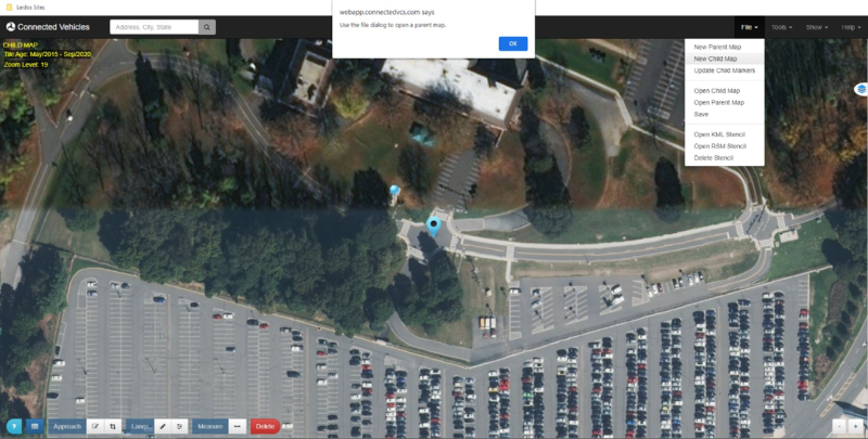
1. Navigate to the address where the ISD message would be created (refer to figure 55).

This screenshot demonstrates an example of navigating to an address to create an ISD message in the Intersection Situation Data (ISD) Message Creation Tool. The address bar is at the top left-hand corner of the screen and an address is typed in.

Source: USDOT.
Figure 55. Screenshot. Address Navigation.

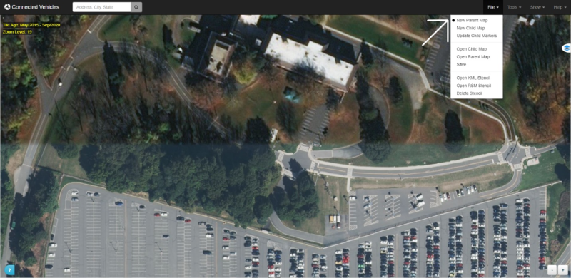
2. From the top navbar, go to New Parent Map to enter parent map editing mode (refer to figure 56).

This screenshot demonstrates the new parent map option in the Intersection Situation Data (ISD) Message Creation Tool. An arrow points to the New Parent Map option.

Source: USDOT.
Figure 56. Screenshot. New Parent Map.

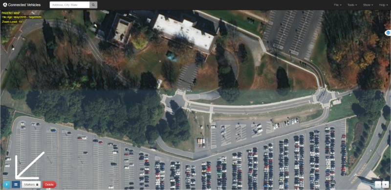
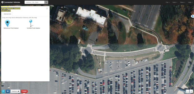
3. Select the Builder icon to bring up the builder menu (refer to figure 57). In the Intersection tab, you should see the two intersection options, including the Reference Point Marker (refer to figure 58).

This screenshot demonstrates the Builder menu icon in the Intersection Situation Data (ISD) Message Creation Tool. The icon is at the bottom-left hand corner of the application and is the second icon from the left.

Source: USDOT.
Figure 57. Screenshot. Builder icon.

This screenshot depicting the Reference Point Marker in the Intersection Situation Data (ISD) Message Creation Tool. A map pin icon represents the Reference Point Marker.

Source: USDOT.
Figure 58. Screenshot. Reference point marker.

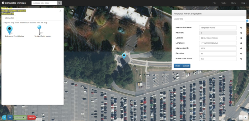
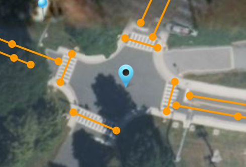
4. Click and drag a reference point marker to the center of your intersection. You can only place one reference point per message.

  • Note that the Markers Control becomes enabled once the marker is placed (refer to figure 59).
  • You may drag around the marker after being placed to tweak its location.
  • Click on the marker to open and close the Configuration dialog. From here you can view its Latitude, Longitude, Elevation, and other variables.
  • You may toggle the control back off or click Done once you are finished tweaking the location of the marker to lock it place.
This screenshot shows the Marker configuration dialog. A menu appears in the top right-hand corner of the Intersection Situation Data (ISD) Message Creation Tool and is labeled “Reference Point Configuration. The menu allows the user to change the location of the marker through changing the values of the following options: intersection name, latitude, longitude, intersection ID, elevation, and master lane width.

Source: USDOT.
Figure 59. Screenshot. Marker configuration dialog.

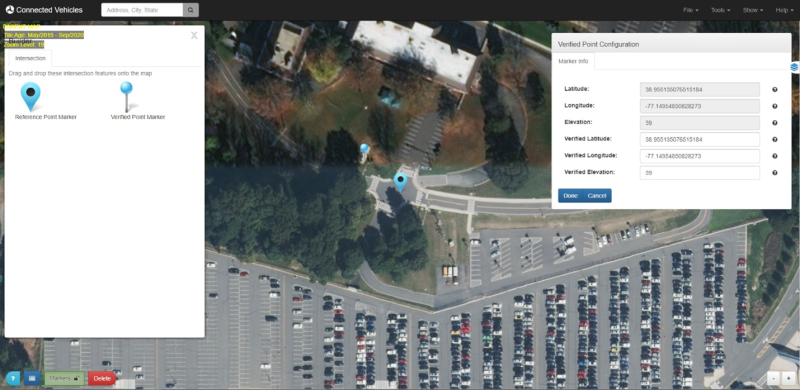
5. Click and drag the Verified Point Marker to a known, surveyed location on the map.

  • Click on the marker to open up the Configuration dialog (refer to figure 60). You can view the location of the marker on the map, as well as view and modify the verified location of the marker.
  • Check the verified marker information and edit as necessary. Click Done when finished.
This screenshot shows the verified point configuration menu. A menu appears in the top right-hand corner of the Intersection Situation Data (ISD) Message Creation Tool and is labeled 'Verified Point Configuration. The menu allows the user to change the location of the verified point through changing the following options: verified latitude, verified longitude, verified elevation.

Source: USDOT.
Figure 60. Screenshot. Verified point configuration.

6. Close the Builder once you are finished placing the two markers.

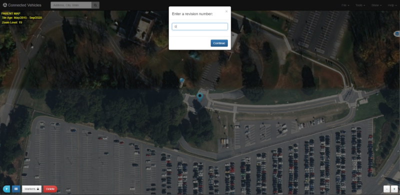
7. Go to File then Save and enter your revision number (refer to figure 61).

This screenshot shows the revision number menu in the Intersection Situation Data (ISD) Message Creation Tool. The menu prompts the user to enter a revision number.

Source: USDOT.
Figure 61. Screenshot. Setting revision number.

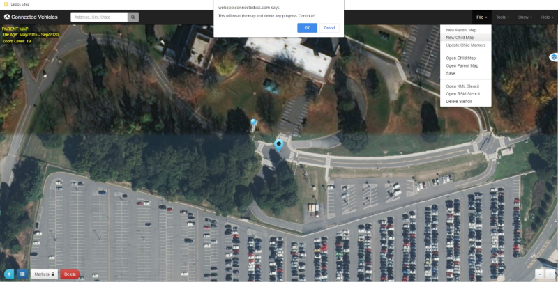
8. Save file and continue to create a New Child Map in the file menu. Selecting new child map will bring up a dialog box. Click OK if your parent map has been saved (refer to figure 62).

This screenshot demonstrates the creation of a new child map in the Intersection Situation Data (ISD) Message Creation Tool. Under File at the top right-hand corner of the tool, New Child Map is selected. A dialog box at the top middle of the screen appears and says, 'This will reset the map and delete any progress. Continue?' The options are OK or Cancel.

Source: USDOT.
Figure 62. Screenshot. New child map.

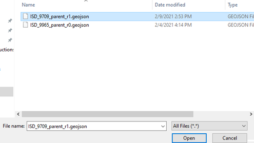
A second dialog box will direct to opening a parent map, which is used to build the child map (refer to figure 63). Select the saved parent map and open (refer to figure 64).

This screenshot demonstrates the creation of a new child map in the Intersection Situation Data (ISD) Message Creation Tool. Under File at the top right-hand corner of the tool, New Child Map is selected. A dialog box at the top middle of the screen appears and says, 'Use the file dialog to open a parent map.'

Source: USDOT.
Figure 63. Screenshot. New child map.

This screenshot demonstrates the selection of a parent map file. The file is formatted as GEOJSON file.

Source: USDOT.
Figure 64. Screenshot. Selecting parent map.

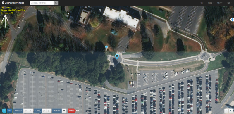
9. Once opened, the information from the parent map will be imported to the new child map (refer to figure 65).

This screenshot shows a new child map in the Intersection Situation Data (ISD) Message Creation Tool. An arrow points to text at the top left-hand corner of the map, and the text says, 'CHILD MAP Tile Age: May/2015 – Sep/2020 Zoom Level: 19.'

Source: USDOT.
Figure 65. Screenshot. New child map.

Defining the Region

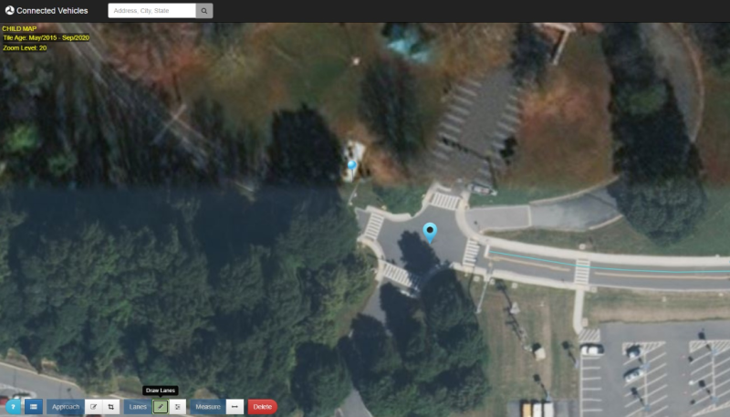
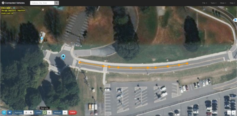
1. Toggle ON the Draw Lane control from the bottom Control Panel. A lane region is started from the STOP bar, down the center of the lane, until about 1000 feet away from the intersection. Single click to drop points, double click to stop drawing. (refer to figures 66, 67, 68).

This screenshot shows the Intersection Situation Data (ISD) Message Creation Tool Draw Lane tool. An arrow points to the tool at the bottom left-hand corner of the screen. The draw lane tool is the fifth button from the left.

Source: USDOT.
Figure 66. Screenshot. Draw Lane

This screenshot shows the Intersection Situation Data (ISD) Message Creation Tool Draw Lane tool. The draw lane tool is the fifth button from the left in the menu at the bottom left-hand corner of the screen. The draw lane tool is toggled on.

Source: USDOT.
Figure 67. Screenshot. Draw lane in progress.

This screenshot shows a complete lane in the Intersection Situation Data (ISD) Message Creation Tool. A dotted line segment on the lane represents the drawn lane.

Source: USDOT.
Figure 68. Screenshot. Completed lane.

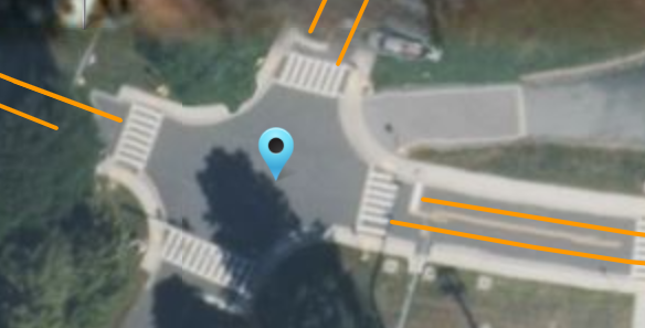
2. Ingress lanes are marked from the beginning of the STOP bar and egress lanes are marked from the beginning of the CROSSWALK (refer to figure 69).

This screenshot shows ingress and egress lanes marked on a map in the Intersection Situation Data (ISD) Message Creation Tool.

Source: USDOT.
Figure 69. Screenshot. Ingress and egress lanes.

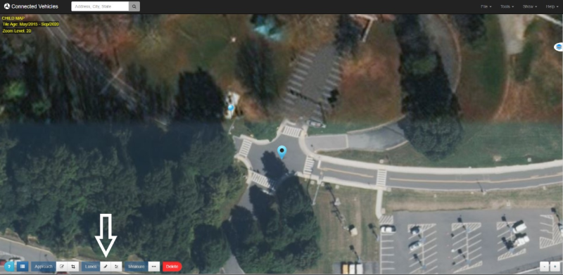
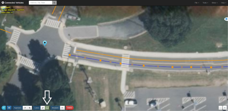
3. Lanes can be edited using the Edit Lanes button at the bottom of the screen. Selected lane will show markers, which can be moved (refer to figure 70).

This screenshot demonstrates the Edit Lanes tool in the Intersection Situation Data (ISD) Message Creation Tool. An arrow points to the tool which appears at the bottom left-hand corner of the screen and is the sixth tool from the left. Markers appear on an existing lane demonstrating that the lane can be edited using the Edit Lanes tool.

Source: USDOT.
Figure 70. Screenshot. Edit lanes.

4. Crosswalks are marked using the same Draw Lanes tool (refer to figure 71).

This screenshot demonstrates crosswalks drawn in the Intersection Situation Data (ISD) Message Creation Tool. Line segments represent the crosswalk locations on the map.

Source: USDOT.
Figure 71. Screenshot. Drawing crosswalks.

5. An approach is drawn by selecting the Draw Approaches tool at the bottom of the screen. Click and drag across a region to draw (refer to figure 72).
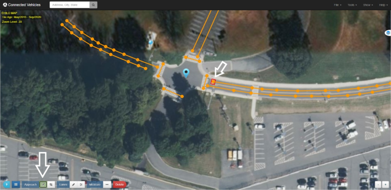
This screenshot demonstrates the Draw Approaches tool in the Intersection Situation Data (ISD) Message Creation Tool. An arrow points to the tool which appears at the bottom left-hand corner of the screen and is the third tool from the left. Another arrow points to where an approach is drawn on the map.

Source: USDOT.
Figure 72. Screenshot. Drawing an approach.

6. Approaches can be edited by selecting the Edit Approaches tool at the bottom of the screen. Clicking on an approach will allow you to move and adjust the approach (refer to figure 73).
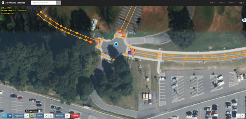
This screenshot demonstrates the Edit Approaches tool in the Intersection Situation Data (ISD) Message Creation Tool. The tool appears at the bottom left-hand corner of the screen and is the fourth tool from the left. The drawn approaches are indicated by boxes on the map.

Source: USDOT.
Figure 73. Screenshot. Editing an approach.

7. Feel free to save the maps at any time. This way, previous revisions can be accessed if desired.

8. Lane configurations can be updated by clicking on the first node drawn at each lane (refer to figure 74).
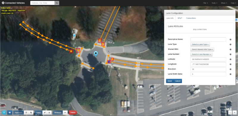
This screenshot demonstrates lane configuration in the Intersection Situation Data (ISD) Message Creation Tool. A window titled 'Lane Configuration' is open on the screenshot. It has the options: Descriptive Name, Lane Type, Shared With, Lane Number, Latitude, Longitude, Elevation, Lane Width Delta.

Source: USDOT.
Figure 74. Screenshot. Lane configuration.

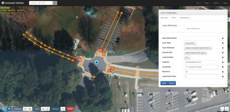
9. Set the Lane Type and Lane Number for each node in the intersection (refer to figure 75).

This screenshot shows the lane nodes on the Intersection Situation Data (ISD) Message Creation Tool. The nodes are labeled with their lane number.

Source: USDOT.
Figure 75. Screenshot. Lane configuration.

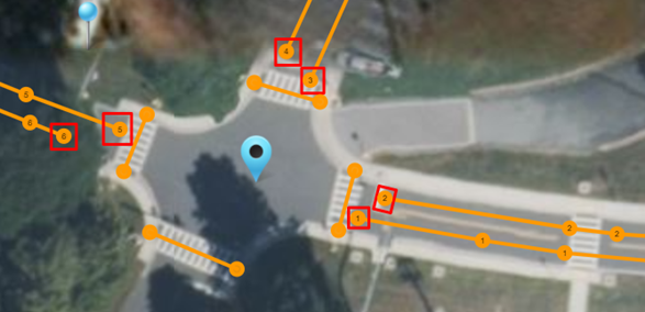
10. Crosswalks can be set and numbered as well (refer to figure 76).

This screenshot demonstrates crosswalk configuration in the Intersection Situation Data (ISD) Message Creation Tool. A window titled 'Lane Configuration' is open on the screenshot. It has the options: Descriptive Name, Lane Type, Shared With, Lane Number, Latitude, Longitude, Elevation, Lane Width Delta. In this screenshot, the Lane Type is set to 'Crosswalk.''

Source: USDOT.
Figure 76. Screenshot. Crosswalk configuration.

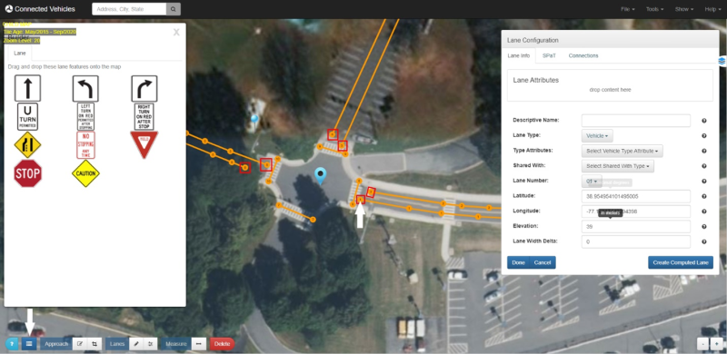
11. Type Attributes and Shared With can be selected if needed for a specific lane in the lists (refer to figure 77).
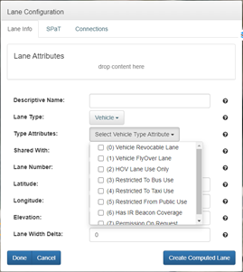
This screenshot shows the Lane Configuration window in the Intersection Situation Data (ISD) Message Creation Tool. The Type Attributes option menu is expanded and demonstrates some of the options.

Source: USDOT. Figure 77. Screenshot. Additional lane configurations.

12. Approach Configurations are added by clicking on each approach border (refer to figure 78). This allows the user to set the approach as either an Ingress, Egress, Both, or None.
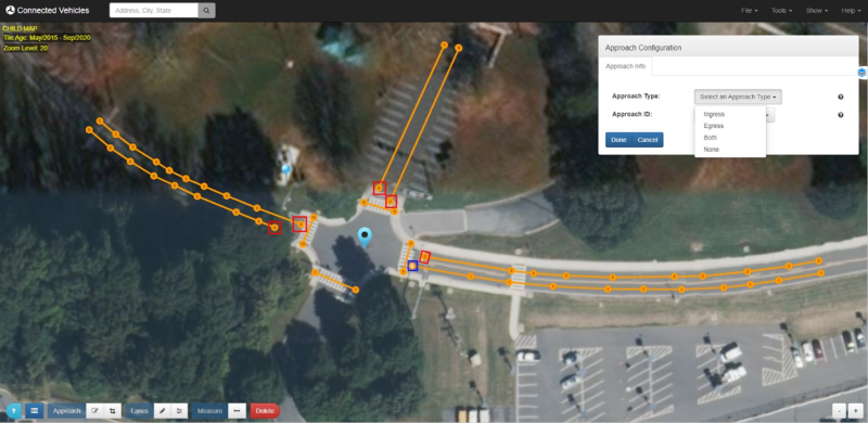
This screenshot shows the Approach Configuration window in the Intersection Situation Data (ISD) Message Creation Tool. There are two configuration settings: Approach Type and Approach ID. The Approach Type has a dropdown menu with options and is expanded in the screenshot. The options are Ingress, Egress, Both, and None. The approaches are indicated by boxes.

Source: USDOT.
Figure 78. Screenshot. Approach configurations.

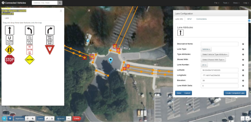
13. In order to define how the lanes and crosswalks interact, the Lane Attributes must be edited. Select a lane node to open the Lane Configuration window, then open the Builder tool (refer to figure 79).

This screenshot shows the builder tool and lane configuration windows open in the Intersection Situation Data (ISD) Message Creation Tool.

Source: USDOT.
Figure 79. Screenshot. Lane attributes.

14. When both windows are open, a Lane Feature can be drag-and-dropped to the Lane Attributes section in the Lane Configuration window (refer to figure 80).

This screenshot shows the builder tool and lane configuration windows open in the Intersection Situation Data (ISD) Message Creation Tool.

Source: USDOT.
Figure 80. Screenshot. Lane attributes.

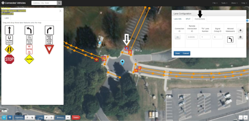
15. Another method for assigning lane attributes can be done using the Connections tab. Here, a lane-to-lane connection through the intersection can be specified. The IDs in this tab are specified by the particular intersection’s traffic signal controller configurations.

A left turn connection example from Lane 4 to Lane 1 is shown (refer to figure 81).

This screenshot shows the builder tool and lane configuration windows open in the Intersection Situation Data (ISD) Message Creation Tool.

Source: USDOT.
Figure 81. Screenshot. Left turn attribute.

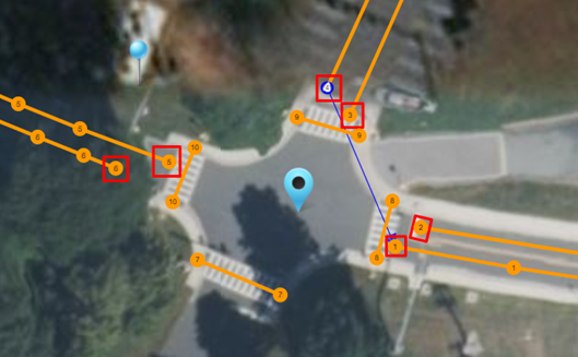
16. Once the connection is made and Done is selected, a connection on the map can be seen when the approach is selected (refer to figure 82).

a. All lanes are configured individually.

This screenshot shows the left turn attribute added to the configured lanes in the Intersection Situation Data (ISD) Message Creation Tool. An arrow points from the lane labeled 4 to the lane labeled 1.

Source: USDOT.
Figure 82. Screenshot. Added left turn attribute.

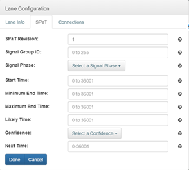
17. The final lane configuration is the SPaT tab. Here, you can input all the SPaT information for each lane (refer to figure 83). This is optional, however, and not covered in this MAP-specific tutorial.

This screenshot shows the signal phase and timing (SPaT) tab under the Lane Configuration window in the Intersection Situation Data (ISD) Message Creation Tool. The user can input the follow SPaT information: SPaT Revision, Signal Group ID, Signal Phase, Start Time, Minimum End Time, Maximum End Time, Likely Time, Confidence, Next Time.

Source: USDOT.
Figure 83. Screenshot. SPaT configurations.

Finish and Encode or Deposit

Encode your ISD message to the intersection once you are finished building it.

1. Open Encode/Deposit dialog

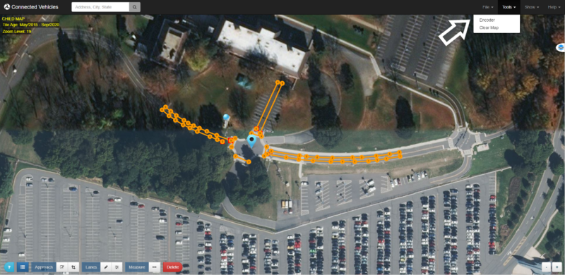
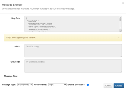
  1. Click on Tools Encode to load the deposit window (refer to figure 84). Unless there are errors, a JSON message should already be generated from the map data. Its contents will appear in the Message text box (refer to figure 85).
  2. Verify the contents of the message.
This screenshot shows the Encoder tool in the Intersection Situation Data (ISD) Message Creation Tool. The tool is under the Tools menu at the top right-hand corner of the tool. A dropdown menu is under the Tools menu, and an arrow points to the Encoder tool.

Source: USDOT.
Figure 84. Screenshot. Open Encode/Deposit window

This screenshot shows the Message Encoder in the Intersection Situation Data (ISD) Message Creation Tool. The Message Encoder has subtext that states, 'Check the generated map data JSON then ‘Encode’ it as SDC/SDW ISD message.' The Message Encoder has Map Data, ASN.1, and UPER Hex fields. The map data is prepopulated. The message type in the screenshot is 'Frame+Map,' the node offsets are set to 'Tight, and enable elevation is toggled on.

Source: USDOT.
Figure 85. Screenshot. Message Deposit Window.

2. Select desired Message Type (refer to figure 86)

  1. ISD – ISD Safety Message
  2. Map – Raw map contents
  3. Frame+Map – SAE J2735 Message Frame message with MAP contents
  4. SPaT – If SPaT sample data is included in the map message
  5. Frame+SPaT – SAE J2735 Message Frame message with SPaT contents
  6. SPaTRecord – SPaT Record portion of ISD message

3. Select desired nodes offsets encoding (in the descending order of the message size)

  1. Tight – uses the absolute minimal SAE J2735 Node-XY-?? offset value encoding for each node (refer to figure 86)
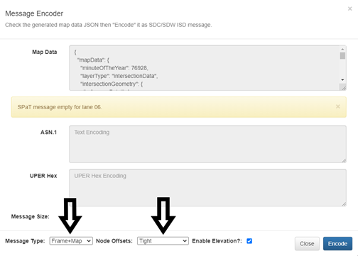
This screenshot shows the Message Encoder in the Intersection Situation Data (ISD) Message Creation Tool. The Message Encoder has subtext that states, 'Check the generated map data JSON then ‘Encode’ it as SDC/SDW ISD message.' The Message Encoder has Map Data, ASN.1, and UPER Hex fields. Arrows point to the message type and node offset fields at the bottom of the menu. The message type in the screenshot is 'Frame+Map,' the node offsets are set to 'Tight,' and enable elevation is toggled on.

Source: USDOT.
Figure 86. Screenshot. Message type and node offsets.

4. Encode the Message

  1. Press the Encode button to generate the UPER encoding (refer to figure 87)
  2. The Hex text area box will display the hex encoded message if successful, or an error message if unsuccessful.
  3. The ASN.1 text area box will display the ASN.1 encoded message if successful, or an error message if unsuccessful.
  4. Note that although the cursor in all text areas is the prohibition sign, because the text areas are read-only, you can select the content of any text area and copy it via standard shortcut keys or a context menu available on the right-click. The easiest way to copy all content from a text area is to click in the text area and then type Ctrl-A to select all lanes and Ctrl-C to copy to clipboard.
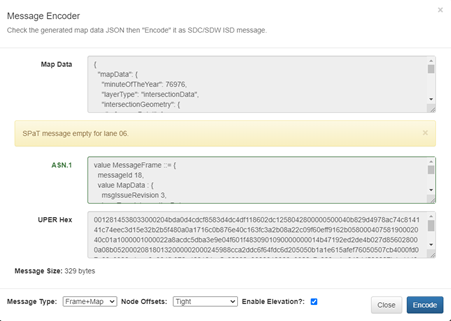
This screenshot shows the Message Encoder in the Intersection Situation Data (ISD) Message Creation Tool. The Message Encoder has subtext that states, 'Check the generated map data JSON then ‘Encode’ it as SDC/SDW ISD message.' The Message Encoder has Map Data, ASN.1, and UPER Hex fields. The map data, ASN.1, and UPER hex fields are populated with information. The message size is 329 bytes. he message type in the screenshot is 'Frame+Map,' the node offsets are set to 'Tight,' and enable elevation is toggled on.

Source: USDOT. Figure 87. Screenshot. Frame+Map encoded message.

5. When encoding as Frame+Map or Map, the Hex text area will output the UPER encoded SAE J2735 payload for broadcast. This payload must be copied an edited to be used with V2X Hub.

6. Copy and paste the payload into a text editor and delete the first 4 octets (8 characters).

  1. a. Example: 00128145

7. Save the file with a name for your intersection.

  1. a. Example: MAP_9709_UPER.txt

Previous | Next

Stay Connected

twitter logo
facebook logo
linkedin logo
youtube logo
U.S. DOT instagram logo

For inquiries regarding the ITS PCB Program, please contact the USDOT Point of Contact below.
J.D. Schneeberger
Program Manager, Knowledge and Technology Transfer
John.Schneeberger@dot.gov

U.S. Department of Transportation (USDOT) | 1200 New Jersey Avenue, SE | Washington, DC 20590 | 800.853.1351
U.S. DOT | USA.gov | Privacy Policy | FOIA | Budget and Performance | No Fear Act
Cummings Act Notices | Ethics | Web Policies & Notices | Vulnerability Disclosure Policy | Accessibility