skip to main content

← Table of Contents

Cohda MK5 RSU Functionality Test

Items Needed

  • CAVe-in-a-box w/ MK5 RSU.
  • 5.9GHz antenna (2).
  • GPS Antenna.
  • Ethernet Cable.
  • POE Injector.
  • External PC.

Basic Setup

  1. Attach all antennas per figure 49.
    1. Antennas are connected to the RSU via extension cables in the box.
This photo shows a mounted roadside unit.

Source: FHWA.
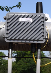
Figure 49. Photo. External RSU setup.

  1. Connect RSU to POE Injector via appropriate Ethernet cable.
    1. Connect POE Injector data output to Network Switch.
  2. Connect PC to Network switch or Wireless Router.
  3. Set the PC Ethernet/Wireless IPv4configuration to:
    1. IP Address: 192.168.0.100
    2. Subnet Mask: 255.255.255.0
    3. Gateway: 192.168.0.1

Testing Operation

  1. Open a Terminal and enter:
    1. ssh rsu@192.168.0.40
    2. If prompted to continue connecting, enter: yes
    3. Password: rsuadmin
    4. Refer to figure 48.
  2. The Terminal is now logged into the MK5 RSU.Type:
    1. sudo fim -l
    2. Refer to figure 50 for the output.
This screenshot shows the output of the MK5 roadside unit (RSU).

Source: FHWA.
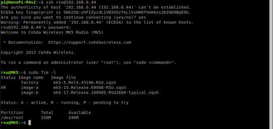
Figure 50. Screenshot. Checking MK5 RSU firmware.

  1. The firmware should point with “AR” tomk5-15.Release.69988-RSU.sqsh or later
    1. Refer to figure 50 above.
  2. To ensure GPS is running, enter:
    1. date
    2. The output should be the current date and time
    3. If date is not correct, move box to a location with better signal
  3. To ensure Map and SPaT messages are being transmitted from the RSU, enter:
    1. ifconfig
    2. From the output, interfaces cw-mon-txa andcw-mon-txb will be seen. Note: MAP andSPAT must be forwarded to the RSU for it to transmit these messages.
    3. Refer to figure 51.
    4. Run: tcpdump–i cw-mon-txb –xx | grep “00 *13”
    5. Stop the process with <Ctrl>c.
    6. Refer to figure 52 for output.
    7. Run: tcpdump–i cw-mon-txb –xx | grep “00 *12”
    8. Stop the process with <Ctrl>c
    9. Refer to figure 53 for output.
This screenshot shows the network interfaces output. Interfaces cw-mon-txa and cw-mon-txb are on the output log.

Source: FHWA.
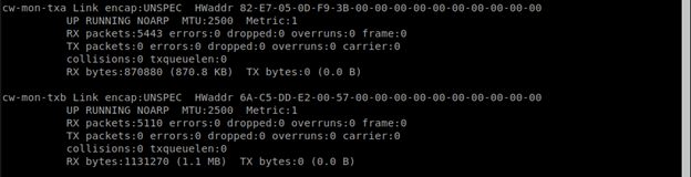
Figure 51. Screenshot. Network interfaces output.

This screenshot shows signal phase and timing (SPaT) message transmission.

Source: FHWA.
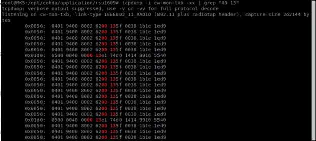
Figure 52. Screenshot. Observing SPaT message transmission.
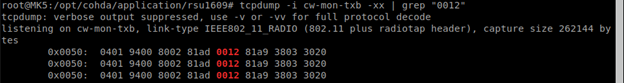
This screenshot shows MAP message transmission.

Source: FHWA.
Figure 53. Screenshot. Observing MAP message transmission.

Before continuing to the BSM section, BSM forwarding on the RSU must be set up. This is called WSM Forwarding and is generally set up automatically with a script. Settings may be checked:

cd /mnt/rw/rsu1609/conf

cat user.conf

Additional radio setting may be checked:

cd /mnt/rw/rsu1609/conf

cat stack.conf

Verify forwarding BSM and Mobility messages are forwarded:

tcpdump port 26789

Refer to figure 54 for output.
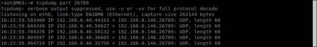
This screenshot shows the terminal indicating the roadside unit (RSU) is forwarding basic safety messages (BSMs).

Source: FHWA.
Figure 54. Screenshot. RSU forwarding BSM.

Previous | Next

Stay Connected

twitter logo
facebook logo
linkedin logo
youtube logo
U.S. DOT instagram logo

For inquiries regarding the ITS PCB Program, please contact the USDOT Point of Contact below.
J.D. Schneeberger
Program Manager, Knowledge and Technology Transfer
John.Schneeberger@dot.gov

U.S. Department of Transportation (USDOT) | 1200 New Jersey Avenue, SE | Washington, DC 20590 | 800.853.1351
U.S. DOT | USA.gov | Privacy Policy | FOIA | Budget and Performance | No Fear Act
Cummings Act Notices | Ethics | Web Policies & Notices | Vulnerability Disclosure Policy | Accessibility