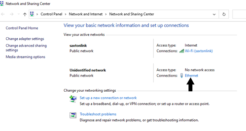
skip to main content

← Table of Contents

Savari MW1000 Onboard Unit – Setup and Test

Items Needed

  • Savari MW1000 OBU.
  • 12V DC Adapter.
  • Lab Mobile DSCR/CV2X antenna.
  • Tablet/Test PC.
  • Ethernet Cable.

Basic Setup

  1. Using the tablet or an external computer, connect to the CradlePoint router using the WiFi SSID Info document.
  2. If your mobile kit does not have a router, you may connect to the OBU via Ethernet. Otherwise, continue to step 7.
    1. Check your IP Address by opening Network and Sharing Center in Windows.
    2. Within that window, click on Ethernet.
    3. Refer to figure 38.
This screenshot shows the Network and Sharing Center in Windows. An arrow points to 'Connections: Ethernet.'

Source: FHWA.
Figure 38. Screenshot. Network and sharing center.
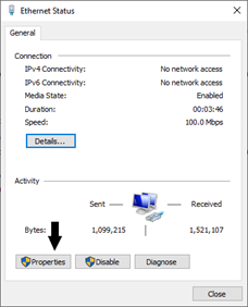
  1. A new window will open. In that window, click on Properties. Refer to figure 39.
This screenshot shows the Ethernet status in Windows. An arrow points to the properties button at the bottom left-hand corner.

Source: FHWA.
Figure 39. Screenshot. Ethernet status.
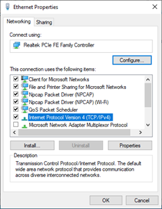
  1. Within the Ethernet Properties window, double-click/open Internet Protocol Version 4 (TCP/IPv4).
    1. Refer to figure 40.
This screenshot shows the Ethernet properties in Windows. A list of items is on the screen with the title, 'This connection uses the following items:' The Internet Protocol Version 4 (TCP/IPv4) item in the list is highlighted.

Source: FHWA.
Figure 40. Screenshot. Ethernet properties.
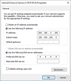
  1. Ensure that Use the following IP address is selected. Input the same configurations as figure 41.
This screenshot shows the Internet Protocol Version 4 (TCP/IPv4) Properties in Windows. The 'Use the following IP address:' option is toggled on, the IP address is set to 192.168.0.200, and the subnet mask is set to 255.255.255.0. The 'Use the following DNS server addresses:' option is toggled on, and the preferred DNS server is set to 8.8.8.8.

Source: FHWA.
Figure 41. Screenshot. IPv4 settings.

  1. Click OK at the bottom of the window, then close all previous Windows.
  2. Open a Terminal/Command Prompt.
    1. If using a tablet, you may not have access to a terminal. Skip to Step 9.
  3. Attempt to ping each device within the Mobile Kit. Refer to figures 42 and 43.
    1. ping 192.168.0.50
    2. To stop ping process: <Ctrl>C.
This diagram illustrates the mobile kit network configuration.

Source: FHWA.
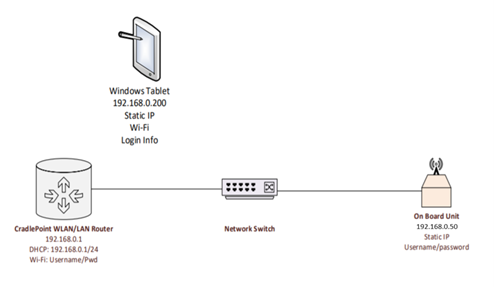
Figure 42. Diagram. Mobile kit network configuration.


This screenshot shows an example of the output by the OBU after being pinged.

Source: FHWA.
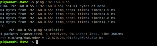
Figure 43. Screenshot. OBU ping output.

  1. Using the acceptance checklist, mark off the box indicating correct IP/Port combinations.
  2. If using a tablet, open PuTTY. Enter settings in the fields shown in figure 44 and click on Open.
    1. Use the password in step 11 to login to the OBU.
    2. Note: Please use 192.168.0.50 and 22
This screenshot shows the PuTTY configuration. The Host Name (or IP address) is 192.168.0.55 and the port is 22. The connection type is SSH. The 'Close window on exit' option is set to 'Only on clean exit.'

Source: FHWA.
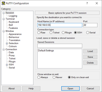
Figure 44. Screenshot. PuTTY example settings.

  1. To connect to OBU via terminal use:
    1. ssh root@192.168.0.50
    2. If prompted to continue connecting, enter: yes
    3. Password: 5@G3p9axINJA
    4. Refer to figure 45 for example output.
This screenshot demonstrates an example of the onboard unit SSH login output.

Source: FHWA.
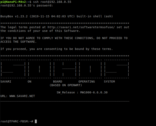
Figure 45. OBU SSH login example.
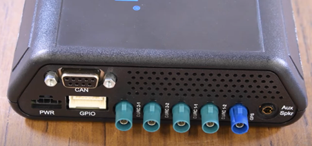
Testing GNSS Operation

  1. Connect the antenna to the OBU.
    1. Make sure the GPS is connected to the blue fakra connection labeled as GPS in figure 46. The Lab Mobile antenna GPS connector is also blue.
    2. The other two can be connected in any order to DSRC1-1 and DSRC 1-2
A photo of the connection ports on an onboard unit (OBU). The OBU pictured has nine ports and are labeled as such (from left to right): PWR, CAN, GPIO, DSRC2-1, DSRC2-2, DSRC1-1, DSRC 1-2, GPS, and Aux Spkr.

Source: FHWA.
Figure 46. Photo. Savari OBU hardware setup.

  1. In order to send BSMs, GPS must first be established:
    1. To check for proper GPS signal, use:
      1. date
      2. The output will be the current date. Refer to figure 47 for example output.
      3. If date is not correct, move box to an area with better reception.
This screenshot is an example of GPS date output.

Source: FHWA.
Figure 47. Screenshot. GPS date output.
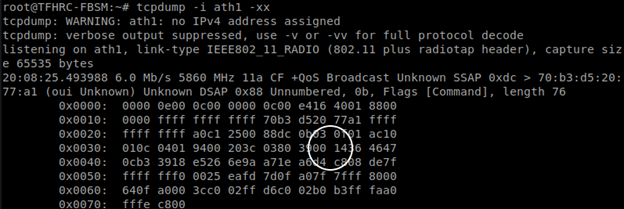
Testing BSM Transmission

  1. To check for BSM transmissions, enter:
    1. tcpdump – i ath1 –xx | grep “00 *14”
    2. The BSM transmission ID is 0014 in Hexadecimal. The ID can be seen below.
    3. Refer to figure 48 for output.
This screenshot demonstrates the output to test basic safety message (BSM) transmission. The transmission hexadecimal ID 0014 is circled on the screenshot.

Source: FHWA.
Figure 48. Screenshot. BSM transmitting output.

Previous | Next

Stay Connected

twitter logo
facebook logo
linkedin logo
youtube logo
U.S. DOT instagram logo

For inquiries regarding the ITS PCB Program, please contact the USDOT Point of Contact below.
J.D. Schneeberger
Program Manager, Knowledge and Technology Transfer
John.Schneeberger@dot.gov

U.S. Department of Transportation (USDOT) | 1200 New Jersey Avenue, SE | Washington, DC 20590 | 800.853.1351
U.S. DOT | USA.gov | Privacy Policy | FOIA | Budget and Performance | No Fear Act
Cummings Act Notices | Ethics | Web Policies & Notices | Vulnerability Disclosure Policy | Accessibility