Source: FHWA.
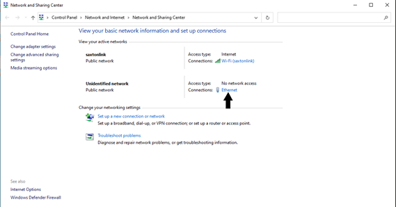
Figure 27. Screenshot. Network and Sharing Center.
Source: FHWA.
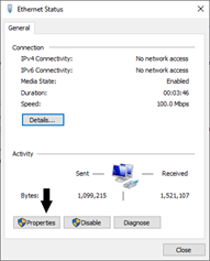
Figure 28. Screenshot. Ethernet status.
Source: FHWA.
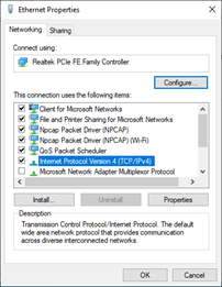
Figure 29. Screenshot. Ethernet properties.
Source: FHWA.
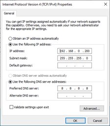
Figure 30. Screenshot. IPv4 settings.
Source: FHWA.
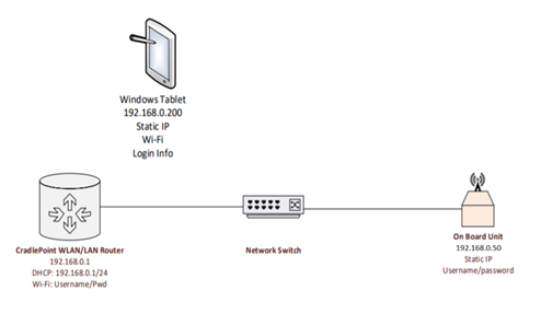
Figure 31. Diagram. Mobile kit network configuration.
Source: FHWA.
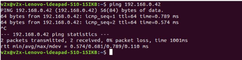
Figure 32. Screenshot. Example positive ping output.
Source: FHWA.
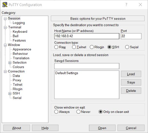
Figure 33. Screenshot. PuTTY settings.
Source: FHWA.
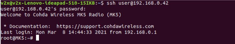
Figure 34. Screenshot. OBU login example.
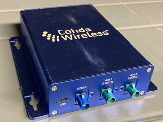
Source: FHWA.
Figure 35. Photo. MK5 OBU hardware setup.
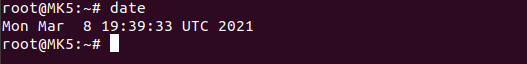
Source: FHWA.
Figure 36. Screenshot. GPS date output.
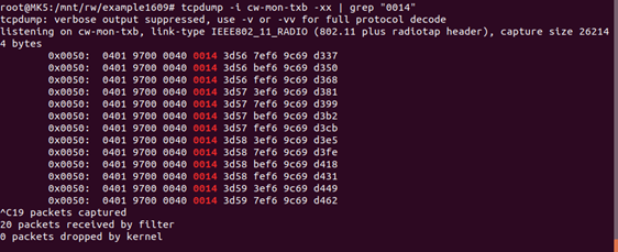
Source: FHWA.
Figure 37. Screenshot. BSM transmitting output.
The radio settings may be changed in the obu.conf file. This file is located in the /mnt/rw/example1609/ directory. Before changes are made, rc.example1609 must be stopped.