← Table of Contents
CAVe-in-a-Box Setup and Test
Items Needed
- CAVe-in-a-Box.
- Optional: External Monitor.
- Optional: Keyboard + Mouse.
- Optional: External Computer.
Basic Setup
- Using the acceptance checklist, make sure all antennas and devices are firmly fastened to the box.
- Mark off each unit on the checklist.
- Connect CAVe-in-a-box surge protector to AC power source.
- On the back of the CAVe-in-a-box, turn on the surge protector.
- All units within the CAVe-in-a-box will power on.
- Component images and names are in the Component Names document.
- Mark results in checklist.
- Connect Mobile Kit to respective power source.
- All units within Mobile Kit will power on.
- Mark results in checklist.
- After a few seconds, all unit LEDs will be powered on.
- Check each unit and mark results on checklist.
- For the other sections, either an external monitor and keyboard + mouse can be plugged into the NanoPi/V2X-Hub computer or an external computer can be connected to the network switch.
- The NanoPi has an Operating System and the V2X-Hub pre-installed.
- If desired, the instructions for setting both up can be found in the NanoPi V2X-Hub Setup document.
- Pre-configured NanoPi Login Information:
- Username: pi
- Password: pi
Traffic Signal Controller
The following steps show which Traffic Signal Controller settings must be changed at a minimum. Every intersection has a different setup. Therefore, some settings are only examples.
- The network configuration settings must be changed to communicate with the V2X Hub
- Address: 192.168.0.92
- Net Mask: 255.255.255.0
- Gateway: 192.168.0.1
- Ping Server: 192.168.0.146
- Refer to figure 8.
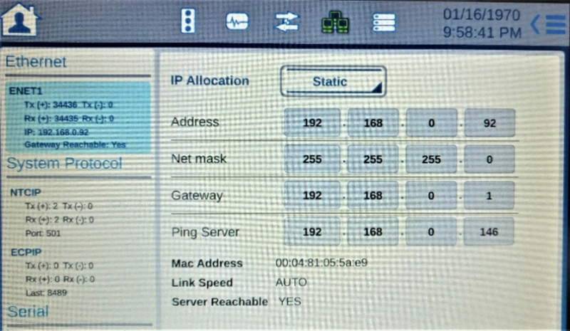
Source: FHWA.
Figure 8. Screenshot. TSC Network Configuration.
- The Phase Order settings can be found on the home page. Select the symbol and adjust to match your intersection’s phase order.
- Barriers separate active phases.
- Tap on a phase symbol or empty box to view edit menu.
- Refer to example in figure 9.
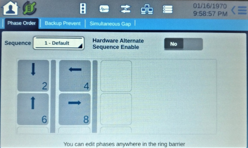
Source: FHWA.
Figure 9. Screenshot. Example phase order settings.
- In the Timing Plans settings, all the separate tabs, seen in figure 9, can be changed to match your desired signal timing.
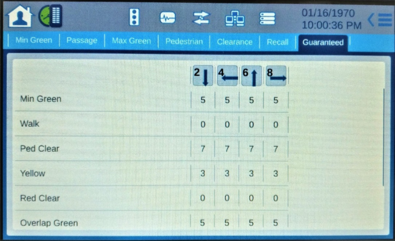
Source: FHWA.
Figure 10. Screenshot. Timing settings.
- There are many other settings available to be changed. Not all need to be adjusted but can be to reflect your desired SPaT messages.
Network Setup
Users connected to the Wireless Router or the LAN Network Switch with an external PC/tablet can ping other devices within the network.
- Attempt to ping each device within the CAVe-in-a-box. Refer to figure 11.
- Example: ping 192.168.0.1.
- To stop ping process: <Ctrl>C.
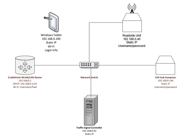
Source: FHWA.
Figure 11. Diagram. CAVe-in-a-box network configuration.
- External Kit IP addresses are checked later in the process.
- Check off the box indicating correct IP/Port combinations.
V2X Hub + SPAT Plugin
- Using the CAVe-in-a-box tablet, open an internet browser and go to:
- Accept the credentials on the page. Refer to figure 12.
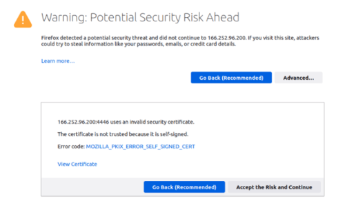
Source: FHWA.
Figure 11. Screenshot. Accept Security Credentials.
- Open a new tab and go to:
- 192.168.0.146
- If using an external computer, you will have to change the IP address in the text box to:
- 192.168.0.146
- Default is 127.0.0.1 if logging in from the Nano Pi.
- Refer to Figure 13 for the text box.
- Login using:
- Username: v2xadmin
- Password: V2xHub#1234
- Refer to figure 13.
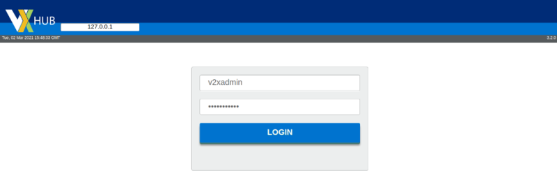
Source: FHWA.
Figure 13. Screenshot. V2X Hub login screen.
- Once logged in, Enable the SPaT plugin if it is not already enabled. Refer to Figure 14.
- If SPaT is not listed as below, the Enabled, Disabled, and External filters may be toggled on or off to show/hide plugins
- Check “Enable SPaT Application” in acceptance checklist.
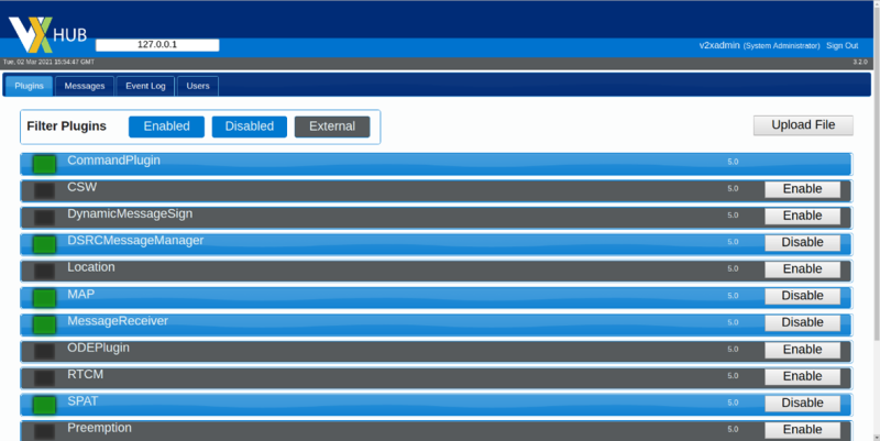
Source: FHWA.
Figure 14. Screenshot. Plugins with enabled and disabled filters ON.
- Click on the SPaT row to expand it:
- Expand the Configuration row and ensure the values match figure 15.
- The SignalGroupMapping section is valid for any standard 4-way intersection.
- It must otherwise be changed to match your intersection’s SPaT settings.
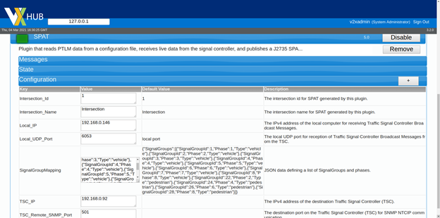
Source: FHWA.
Figure 15. Screenshot. SPaT plugin settings.
- Select the Messages tab at the top to view the messages being received.
- The SPaT-P Subtype will eventually reach a 100 Average Interval.
- Check off results in acceptable checklist.
- Refer to figure 16.
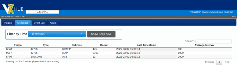
Source: FHWA.
Figure 16. Screenshot. Messages received.
MAP Plugin
To use the MAP plugin in V2X Hub, a map file must be saved in the V2X Hub file path. The map file is an UPER string saved as a .txt file. An example map file is provided in the MAP folder. If desired, a new map file for an intersection may be created following the ISD MAP Tool instructions. An internet connection is required for creating a MAP. Skip to step 5 if using the provided MAP.
- Following the ISD Message Creator tool instructions, move your file into the V2X Hub computer.
- Via USB flash drive:
- Insert your USB containing the folder into the computer.
- Move the file to one of the locations provided in steps 3 and 4
- Via Ethernet:
- Connect external computer to kit’s network switch.
- Change external computer’s wired settings to be within the CAVe network.
- Open a terminal in your external computer.
- cd <directoryContainingFile>
- sudo scp file_name pi@192.168.0.146:/home/pi/V2X-Hub/configuration/arm64/MAP/
- If prompted: Yes
- Note: If an error appears, simply copy and run the recommended command
- Password: pi
- If your kit does not contain a single-board computer (NanoPi, RaspberryPi, etc.) follow for amd64:
- cd <directoryContainingFile>
- sudo scp file_name <username>@192.168.0.146:/home/<username>/V2X-Hub/configuration/amd64/MAP/
- If prompted: Yes
- Password: <password>
- Username and Password are noted within the box, due to various computers being used
- Return to the Plugins tab in V2X Hub and ENABLE the MAP plugin if it is not already enabled.
- Check “Enable MAP Application” in acceptance checklist.
- Click on the MAP row to expand it.
- Expand the Configuration row and ensure the values match figure 17.
- Change the file name in the Value section to match your .txt file.
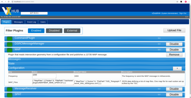
Source: FHWA.
Figure 17. Screenshot. MAP plugin settings.
- Select the Messages tab at the top to view the messages being received.
- The MAP-P Subtype will eventually reach a 1000 Average Interval.
- Refer to figure 16 from the previous section.
- Check off results in acceptable checklist.
DSRC Message Manager
- ENABLE the DSRCMessageManager plugin if it is not already enabled. Refer to figure 18.
- Check “Enable DSRCMessageManager Application” in acceptance checklist.
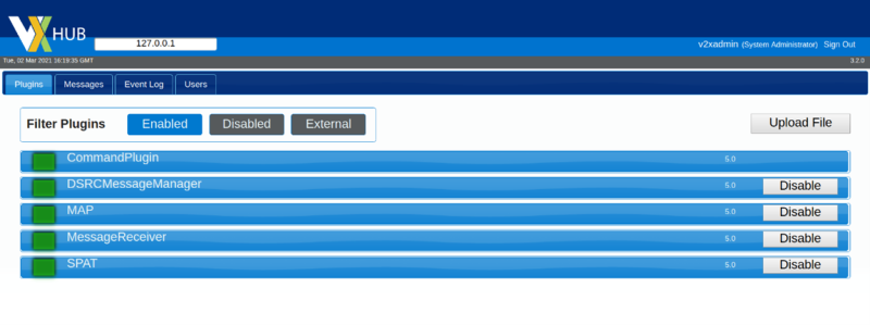
Source: FHWA.
Figure 18. Screenshot. DSRCMessageManager plugin enabled.
- Open a Terminal and enter:
- ssh rsu@192.168.0.40
- If prompted to continue connecting, enter: yes
- Password: rsuadmin
- Refer to figure 19.
- The Terminal is now logged into the MK5 RSU. Type:
- sudo fim –l
- Refer to figure 19 for an example output.
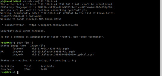
Source: FHWA.
Figure 19. Screenshot. Checking MK5 RSU firmware.
- The firmware should point with “AR” to mk5-15.Release.69988-RSU.sqsh. or a later release
- Refer to figure 19 above.
- To ensure GPS is running, enter:
- date
- The output should be the current date and time.
- If date is not correct, move box to a location with better signal.
- To ensure Map and SPaT messages are being transmitted from the RSU, enter:
- ifconfig
- From the output, interfaces cw-mon-txb will be seen in the list.
- Refer to figure 20.
- Run: tcpdump –i cw-mon-txb –xx | grep “00 13”
- Stop the process with <Ctrl>c.
- Refer to figure 21 for output.
- Run: tcpdump –i cw-mon-txb –xx | grep “0012”
- Stop the process with <Ctrl>c.
- Refer to figure 22 for output.
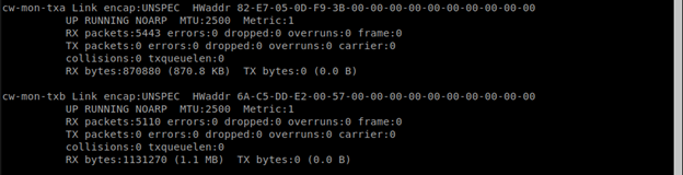
Source: FHWA.
Figure 20. Screenshot. Network interfaces output.
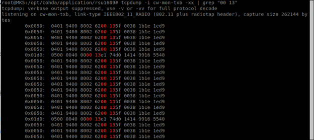
Source: FHWA.
Figure 21. Screenshot. Observing SPaT message transmission.
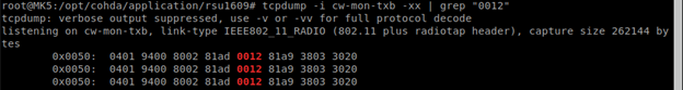
Source: FHWA.
Figure 22. Observing MAP message transmission.
- If neither command runs the correct output, refer to RSU document for troubleshooting.
- Verify forwarding BSM and Mobility messages are set:
- The RSU forwards BSMs—received from the OBU—over to V2X Hub, using port 26789.
- tcpdump port 26789
- Refer to figure 23 for output.
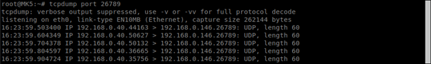
Source: FHWA.
Figure 23. Screenshot. RSU forwarding BSM.
Message Receiver
To ensure BSMs are being received by V2X Hub, transmission from the OBU is first tested.
- Using the tablet or an external computer, connect to the CradlePoint router using the information provided inside the external kit.
- Follow the separate instructions provided to test the BSM transmission from the OBU.
- Once BSM transmission is verified, open V2X Hub on the NanoPi.
- Enable the MessageReceiver plugin if it is not already enabled.
- Refer to figure 24.

Source: FHWA.
Figure 24. Screenshot. Enabled MessageReceiver plugin.
- Click on the MessageReceiver plugin to expand it.
- Expand the Configuration row and ensure the values match figure 25.
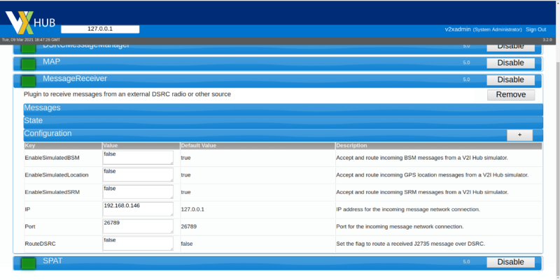
Source: FHWA.
Figure 25. Screenshot. MessageReceiver configuration.
- Navigate to the Messages Tab and verify that BSMs are being received.
- The BSM subtype will eventually reach 100 average interval.
- Refer to figure 26.
Source: FHWA.
Figure 26. Screenshot. BSMs received.
Previous | Next