← Table of Contents
CHAPTER 2. SYSTEM DESIGN
CAVe-in-a-box is an interconnected set of ITS components designed to co-operate to enable the teaching, development, testing, and deployment of CV applications. The kit is designed with a focus on portability, reliability, and usability, so that it can function anywhere, as needed, by anyone, with minimum technical expertise. The purpose of the kit is to allow the technical workforce studying advanced transportation systems to explore and adapt themselves to the new and upcoming technologies that are inevitably going to saturate the market in the coming years. USDOT’s vision of preparing the workforce for the rapidly evolving ITS has played a major role in the outcome of this system.
Some of the features of CAVe-in-a-box include, but are not limited to, the following:
- A hands-on module with different ITS components.
- A design with laboratory use in mind, so that the system can be easily built for classroom and lab work while promoting a real-world infrastructure.
- A portable setup in a box consisting of the most vital technical components that make up the infrastructure and vehicular sides of an ITS.
- A simple plug-and-play module that can be installed virtually anywhere and tested for CAV applications.
- A two-part design:
- Infrastructure unit with a roadside unit (RSU) (infrastructure kit).
- Mobile unit with an onboard unit (OBU) (mobile kit).
- Available updates and extension capabilities.
- Example use cases include lab/classroom education purpose, real-world application development, testing purpose, and field deployment, to name a few.
The design of the infrastructure kit is shown in Figure 1. The kit was designed so that the components can be readily available and easily found from many transportation system vendors.
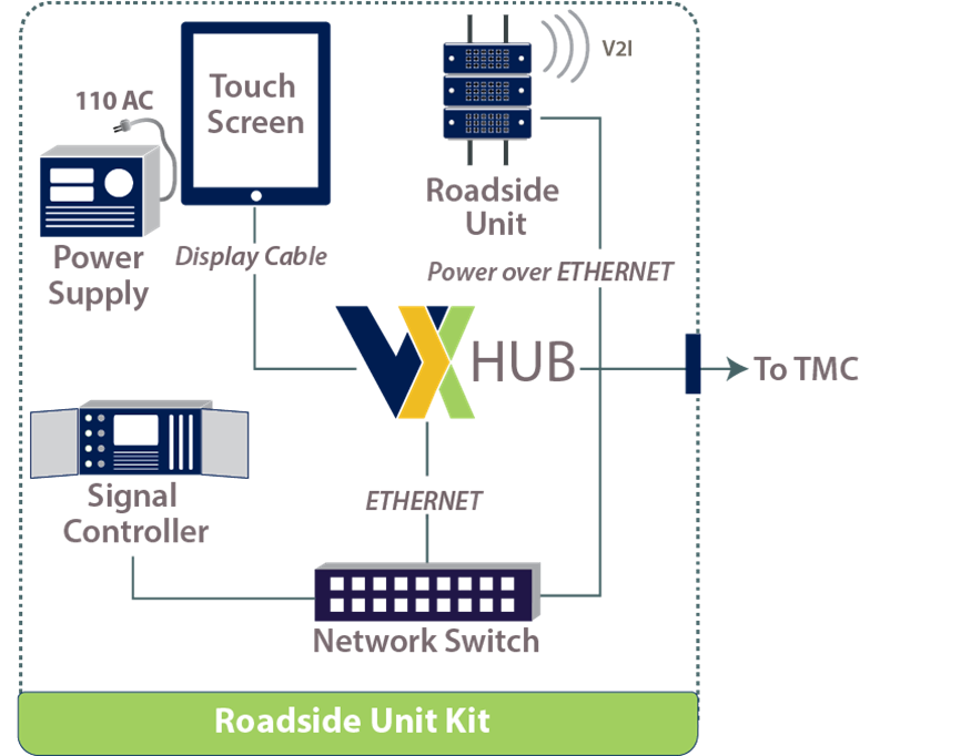
TMC = traffic management center; V2I = vehicle-to-infrastructure.
Figure 1. Diagram. System diagram of the CAVe-in-a-box infrastructure kit.
Source: FHWA.
The components for the CAVe-in-a-box infrastructure kit are listed below in their generic nomenclature:
- Traffic signal controller (TSC)
- RSU
- Vehicle-to-Everything (V2X) Hub computer
- Wired network switch
- Wi-Fi router with cellular network
- Power supply
- Touchscreen personal computer or tablet computer
INFRASTRUCTURE KIT
The purpose of the CAVe-in-a-box infrastructure kit is to support the non-vehicular side of the ITS supporting communication and messaging between applications. The design and components of an assembled infrastructure kit are shown in Figure 1. The infrastructure kit is stationary and located preferably at a site that mimics an active intersection. The kit comes with all the equipment needed to construct a CAV system environment, except the signal head lights. Instead, the real-time status of traffic lights is displayed using the kit’s emulation software. The emulation software is designed to display real-time CAV messages and has a graphical user interface (GUI) representing an intersection like the site where the kit would be deployed. Figure 2 shows the initial version of the infrastructure kit developed as part of the project.
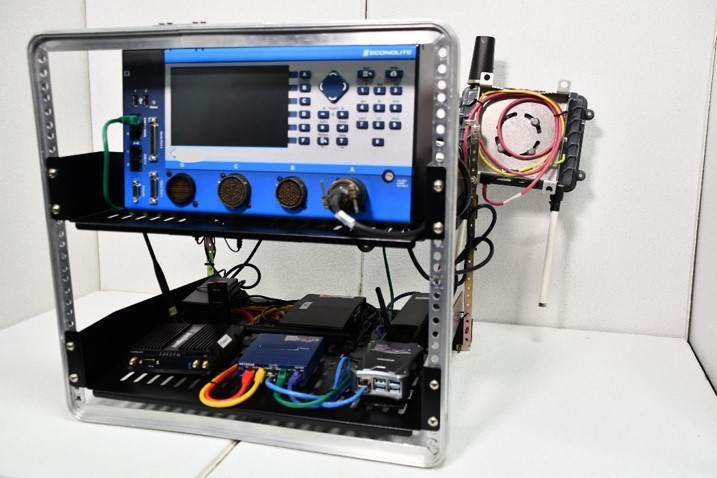
Figure 2. Photo. A built CAVe-in-a-box infrastructure kit.
Source: FHWA.
The integral components of the infrastructure kit are described below.
TSC
The first component required for building a CAVe-in-a-box infrastructure kit is a National Transportation Communications for ITS Protocol (NTCIP) v1202 V3 (USDOT ITS Standards Program, 2009) compliant TSC that has a front panel for necessary configuration and an Ethernet connector port for Simple Network Management Protocol (SNMPv3) messaging (IETF, 1990) between this component and others, at the minimum. The TSC component, shown in Figure 3, will be the actuator for SPaT messages and is connected to an RSU via a V2X Hub computer. The TSC also has an Ethernet connection to the V2X Hub computer inside the kit. The actual physical connection between these devices is shown in later chapters. This component also preferably includes hookups for cabinet wiring that can be exposed outside of the kit, so that an external signal head can be connected to the kit, if needed. The TSC is configured in fixed-timed mode, by default; however, the front panel can be used for reconfiguring the modes, as needed, for any application being tested or demonstrated.
Figure 3. Photos. TSC used as a component of the CAVe-in-a-box infrastructure kit.
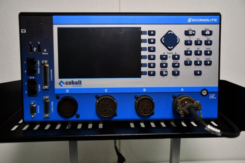
Figure 3A. TSC front view.
Source: FHWA.
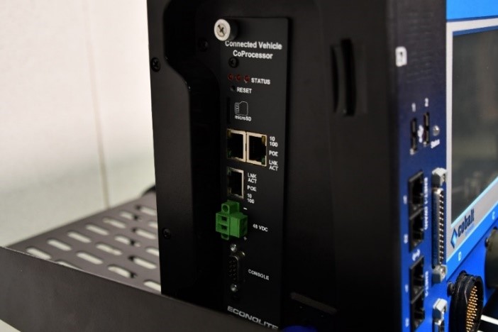
Figure 3B. TSC different connectors in view.
Source: FHWA.
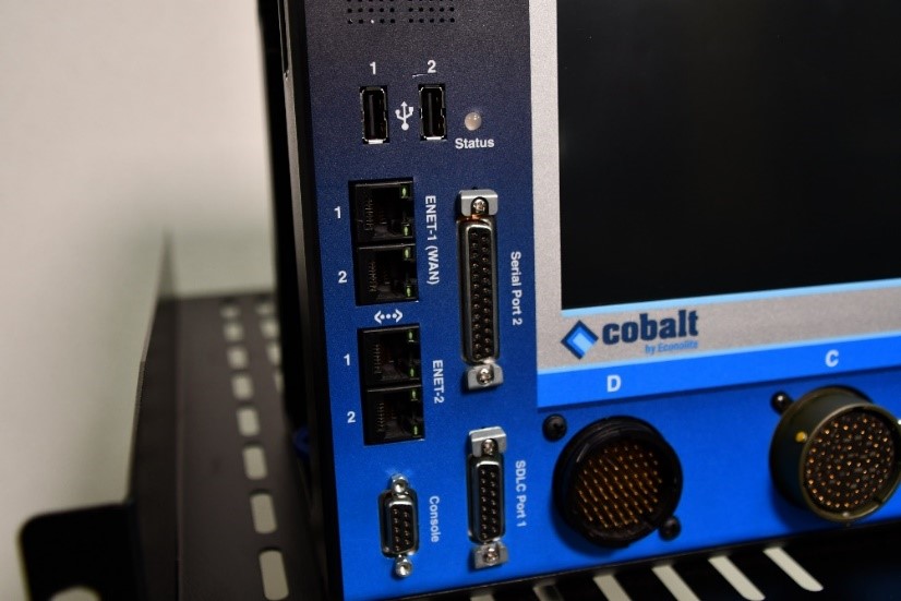
Figure 3C. TSC Connectors on the front panel.
Source: FHWA.
RSU
The RSU is a wireless gateway that allows bidirectional message forwarding between wired and wireless networks. The RSU complies with the USDOT RSU 4.1 specification, and comes with features that are associated with that standard. This includes the immediate forwarding of Wireless Access in Vehicular Environment (WAVE) (J.B. Kenney, 2011) messages to and from a User Datagram Protocol (UDP) application. This feature allows for configuration so that the messages coming from dedicated short-range communications (DSRC) (J.B. Kenney, 2011) or Cellular-Vehicle to Everything (C-V2X) wireless interfaces are forwarded to applications, such as the V2X Hub middleware application running in the V2X Hub computer and vice versa.
Figure 4 shows one of the RSUs used in the CAVe-in-a-box infrastructure toolkit. The RSU adheres to the US DOT RSU 4.1 specification, which enables immediate forward independent of the radio technology. In this iteration, the RSU supports DSRC protocol and is capable of communicating with the 802.11p protocol in the 5.9 GHz band. The 75 MHz available channel width is divided into seven channels. One of these channels is a control channel mostly used for association and detection purposes, while the remaining six channels are dedicated to different ITS applications, including safety, mobility, and management.
The most common vehicular message, broadcasted from vehicles at the rate of 10 messages per second, is the BSM. BSMs use one of the seven channels, particularly channel number 172, so the RSU is configured to listen for BSMs in that channel. The RSU also broadcasts SPaT and MAP messages on the same channel, 172. The WAVE Service Advertisement (WSA) is another type of system message broadcasted by RSUs for advertisement purposes of different services running as an application. The WSA uses channel 178. Therefore, the RSUs usually come with two sets of radio front ends and antennas so that they can transmit or receive at two different frequencies at the same time. However, the DSRC protocol does not allow for transmitting or receiving using the same interface at the same time. A C-V2X RSU may enable sending and receiving messages within the 20 megahertz (MHz) bandwidth.
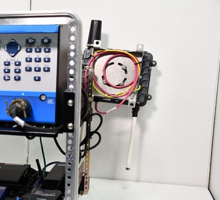
Figure 4. Photo. RSU used as a component of the CAVe-in-a-box infrastructure kit.
Source: FHWA.
V2X Hub
V2X Hub is a dedicated computer module running the middleware software of the same name. V2X Hub imitates a software stack that is a messaging service and an encoder/decoder for Society of Automotive Engineers (SAE) J2735 standard messages (SAE, 2016). It can be installed in a small embedded computer, like the one shown in Figure 5.
The DSRC or C-V2X wireless network used by vehicles and infrastructure use encoded J2735 messages for communication purposes, but these messages are not in human-readable form. V2X Hub works as a translator, translating the encoded J2735 messages into human-readable forms, such as JavaScript Object Notation (JSON) or Extensible Markup Language (XML), which also allows for their use in traditional TMC applications.
For example, a BSM coming in from a nearby vehicle would be decoded using the V2X Hub asn1 decoder and published internally in human-readable form for any subscribing application to receive. This allows for an independent component that can communicate with ITS field units, like OBUs and RSUs, as well as pass messages between these components, human user interfaces, and ITS applications. The V2X Hub computer will have an Ethernet connection with the RSU through a network switch.
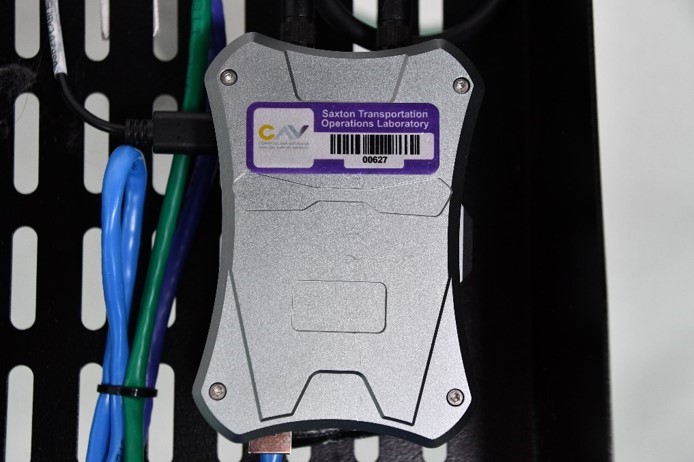
Figure 5. Photo. Embedded computer for V2X Hub software.
Source: FHWA.
A plugin for V2X Hub is an independent sub-component application that uses V2X Hub for its messaging and coding service while supporting an ITS application, such as SPaT messages, traveler information messages (TIMs), MAP messages, personal safety messages (PSMs), and traffic performance analysis, to name a few. Figure 6 shows the set of plugins developed for V2X Hub that are already available for deployment.
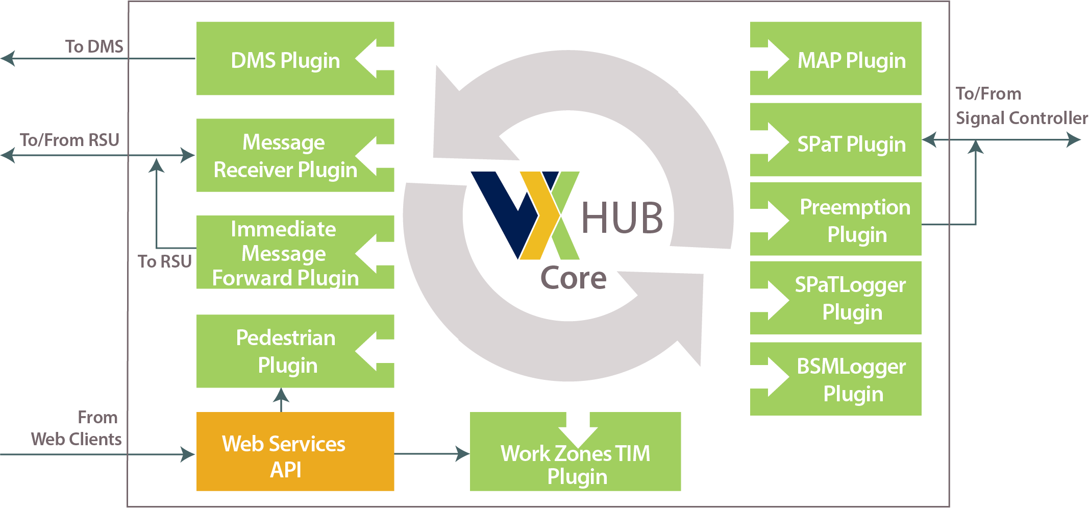
API = application programming interface; BSM = basic safety message; DMS = dynamic message sign;
MAP = Map data; RSU = roadside unit; TIM = traveler information message; SPaT = Signal Phase and Timing.
Figure 6. Diagram. V2X Hub operational design diagram.
For the full description click here.
Source: FHWA.
The following are brief descriptions of the V2X Hub plugins:
- Dynamic Message Sign (DMS) Plugin. This plugin sends information to display messages about road conditions and hazards ahead. The display could be an app or an actual DMS.
- Message Receiver Plugin. This is the receiver plugin that handles incoming J2735 BSMs and Signal Request Messages (SRMs). The plugin decodes/parses the BSMs and SRMs, and broadcasts them using message handlers for other subscriber plugins.
- Immediate Message Forward Plugin. This plugin is used to broadcast J2735 messages through an RSU. The plugin interfaces with the RSU 4.1 specification forwarding feature.
- Pedestrian Plugin. This plugin is designed to handle pedestrian calls. A pedestrian near an intersection would be able to send a personal safety message (PSM) to the V2X Hub, which can alert any nearby drivers of the pedestrian’s presence.
- Work Zones TIM Plugin. This plugin allows remote client, such as a Transportation Management Center, to issue TIM message information to V2X Hub for Immediate Message Forward Plugin to broadcast.
- MAP Plugin. This plugin reads MAP files and broadcasts them through the RSU in MAP messages format. The Immediate Message Forward Plugin handles the broadcasting of the MAP message.
- Preemption Plugin. This plugin receives and checks for preemption at the signalized intersection for emergency vehicles. If the preemption is associated with an emergency vehicle with sirens and lights, the plugin issues preemption movement in phases to the attached TSC.
- SPaT Plugin. This plugin connects with a TSC, reads NTCIP 1202 messages, converts them into J2735 messages, and forwards them to an RSU for immediate broadcast.
- SPaTLogger Plugin. This plugin logs SPaT messages in human-readable form.
- BSMLogger Plugin. This plugin logs any valid BSM received at the V2X Hub in a human-readable form.
Wired Network Switch
The wired network switch is required for the network connection inside the CAVe-in-a-box infrastructure kit. If the components inside the box are set up on the same subnet, it becomes suitable to swap or add any components in the future and wire them through the switch (Cisco, 2020). All communications that occur inside the box through the wires are unicast. A standard 48 Volt direct current (DC) Power over Ethernet (PoE) switch is recommended, as some RSU vendors require PoE as the power source. Figure 7 shows the networked switch with multiple wired connections.
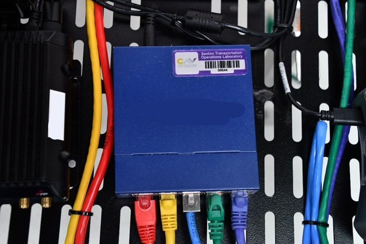
Figure 7. Photo. Wired network switch.
Source: FHWA.
Wi-Fi Router with Cellular Network
Figure 8 shows a Long-Term Evolution (LTE) cellular network-enabled wireless router. Cellular network support in the CAVe-in-a-box infrastructure kit allows remote access and monitoring of the devices. This can inherently change the deployment strategies for CAVe-in-a-box at actual intersections without prior connectivity, as well as testbeds where network connectivity is not present. Using cellular networks for wireless access with a Wi-Fi router allows for connection to all devices in the kit from a monitoring center or indoor lab. By allowing port forwarding in the wireless router, any device can be tagged to a specific port for secure access and control (S. Corrigan, 2016). The infrastructure kit comes with an optional Wi-Fi router with cellular network access, if needed by a test site.
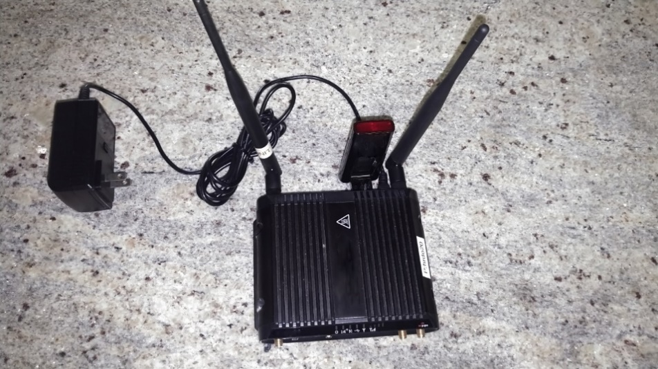
Figure 8. Photo. Wi-Fi router with cellular network access.
Source: FHWA.
Power Supply
The standard 110 volts alternating current (VAC) power supply is the compliant power supply for the CAVe-in-a-box infrastructure kit. Most of the kit components run through altrnating current (AC) power so there is no need for an AC to DC converter. The power supply for the infrastructure kit has an AC wall socket extension that can be connected to a wall socket or a power outlet along an intersection for outdoor testing.
Touchscreen Device
The touchscreen is the only available human interface unit in the CAVe-in-a-box infrastructure kit; however, a laptop with an Ethernet connection to the network switch may be required if there is a need to reconfigure components. The kit and many of the required software applications can be easily accessed using the touchscreen device. The touchscreen is a Windows tablet with Secure Shell (SSH) capability with Ethernet and Wi-Fi support. The touchscreen is connected to the V2X Hub through a High-Definition Multimedia Interface (HDMI) connector (if applicable), Ethernet wired connector, or Wi-Fi access. The touchscreen is used to access the V2X Hub computer using an SSH application, log in to the admin portal, and bring up a terminal emulator so that the packet sniffing applications can be used.
In the future, a set of applications will be deployed on the V2X Hub and the touchscreen tablet for debugging purposes as well as for testing different features of the kit. Figure 9 shows an example touchscreen tablet PC.
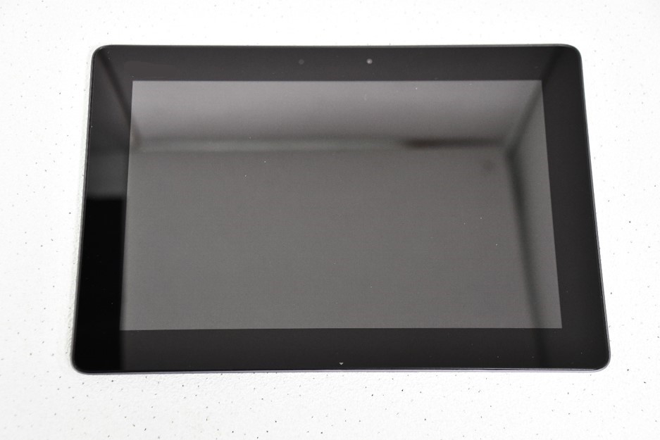
Figure 9. Photo. Touchscreen tablet for GUI.
Source: FHWA.
Mobile Kit
The CAVe-in-a-box mobile kit is installed in the CAVs for testing and educational purposes. With the necessary connections, the mobile kit allows vehicles to communicate with infrastructure and networks. The main purpose of this kit is to broadcast BSMs from a vehicle under study and receive SPaT and MAP messages from intersections. Figure 10 shows a block diagram of the mobile kit in two separate versions (with and without the tablet PC). This is just an outline of the system and certain changes can be made to the design, such as a wireless router installed in the mobile kit. Figure 11 shows the existing build of a mobile kit. It is built as a single box design with necessary components mounted on the inner side. The box opens with the tablet PC facing the user.
The components for the CAVe-in-a-box mobile kit are listed below, in their generic nomenclature:
- OBU
- Controller Area Network (CAN) bus
- Power supply
- Touchscreen PC or tablet computer
- Wi-Fi router with cellular service (optional)
Figure 10. Diagram. System diagram of the CAVe-in-a-box mobile kit.
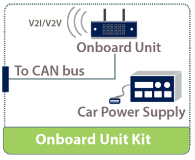
Figure 10A. Mobile kit without touch screen.
Source: FHWA.
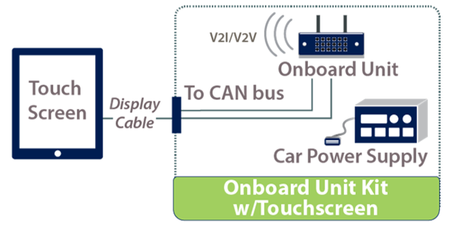
Figure 10B. Mobile kit with touch screen.
Source: FHWA.
The integral components of the mobile kit are described below.
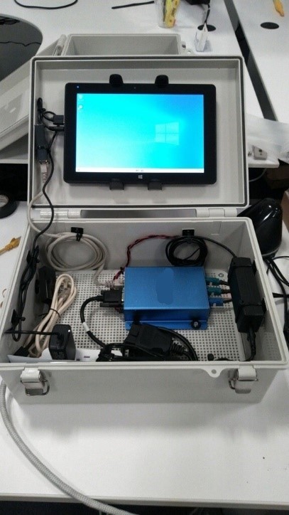
Figure 11. Photo. A built CAVe-in-a-box mobile kit showing different components.
Source: FHWA.
OBU
The OBU is the vehicle counterpart to the RSU. The OBU is installed inside a vehicle, with the OBU antenna mounted on the roof, as close to the center as possible, for the best wireless performance. OBUs are configured to receive SPaT and MAP messages sent from an RSU and log them; however, the log files grow quickly because of the size and frequency of these messages. Therefore, it is advised to frequently delete logs, or relocate the logs if they are important. The OBUs also broadcast BSMs, which are created using the Global Positioning System (GPS) location of the vehicle, as well as data from the CAN bus.
Figure 12. Photos. OBU and the antenna (inset) for DSRC radio.
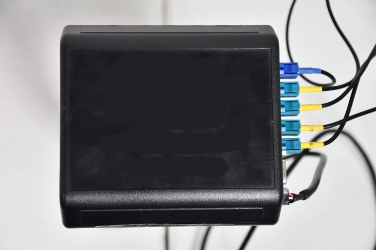
Figure 12A. An OBU
Source: FHWA.
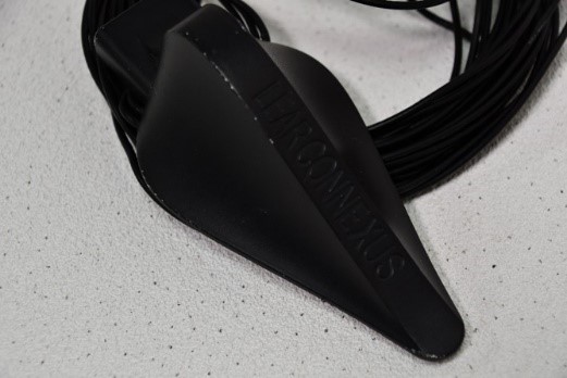
Figure 12B. DSRC Antenna for an OBU
Source: FHWA.
CAN Bus
The CAN bus is a standard used by many process manufacturing systems, as well as vehicles for communicating the control and status information of different subsystem components. The CAN bus is an interface endpoint for the CAN system to allow status messages to be passed outside of the vehicle network. The CAN bus is connected from the vehicle’s Onboard Diagnostics (OBD) II port1 to the CAN input in an OBU. The CAN bus is used to share vehicle safety status messages, such as brake status and steering wheel angle, with the OBU. These messages become an important part of the BSM when transmitted. The CAN input may have to be converted from manufacturer specific descriptions to the generic messages developed by CAMP for the OBUs to work with different vehicles. A translator device configured for a specific vehicle may have to be used to send the vehicle data to the OBU using the generic message IDs that are in the 600-700 range. Please note that while BSMs can contain information obtained from the CAN bus, they can still be created and sent without a CAN connection.
Power Supply
The power supply for the CAVe-in-a-box mobile kit is very similar to that of the infrastructure kit, with only one difference. Because the kit is installed within the vehicle, the outlet resembles a car lighter power socket. Therefore, the components in the vehicle work with DC power.
Touchscreen
The purpose of the touchscreen in the CAVe-in-a-box mobile kit is like its use in the infrastructure kit: it is the human interface for a user to interact with different components of the kit. The touchscreen is connected to the OBU.
Wi-Fi Router with Cellular Service (Optional)
The Wi-Fi router with cellular service allows the user to access the OBU wirelessly using a tablet or laptop with a compatible Wi-Fi interface. If the Wi-Fi router supports cellular networks, such as 3G/4G/LTE, then the components in the mobile kit can be accessed remotely. This enables remote configuration of the mobile kit in test vehicles. There are three options for mobile kit design: (a) with a Wi-Fi cellular component, (b) with a Wi-Fi-only component, or (c) without a Wi-Fi or cellular component. The version of the mobile kit that lacks Wi-Fi and cellular components will have a Universal Serial Bus (USB) wired connector for tablet or laptop PC.
PHYSICAL CONNECTIONS
This section details the connection and ports available in the CAVe-in a-box, as well as the different interconnections among the individual components. The objective of this section is to identify varieties of interconnections in the system and identify external ports for future enhancements. Below are the different types of connections required for the kit to function.
The following types of connectors are required:
- Power. Every component in the kit requires a DC or an AC power supply. As shown in Figure 13 and Figure 14, the power supply unit in the infrastructure kit can provide up to 120 V/ 15 A surge-protected and distribute it to each component using a power strip connector that will support it. The RSU needs PoE for powering requirements. The PoE switch is powered by AC power and provides the 48 VDC/ 30 W power needed by the RSU. Each component of the kit comes with its power adapter(s); therefore, the power strip is enough to support the power needs.
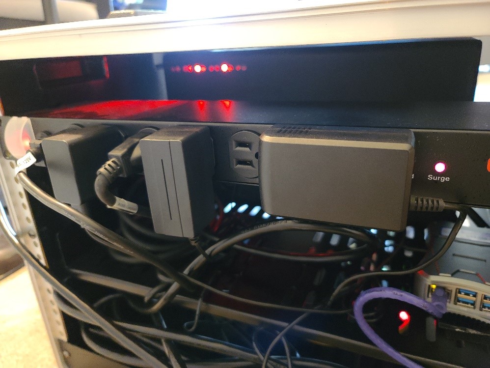
Figure 13. Photo. Power strip with multiple sockets.
Source: FHWA.
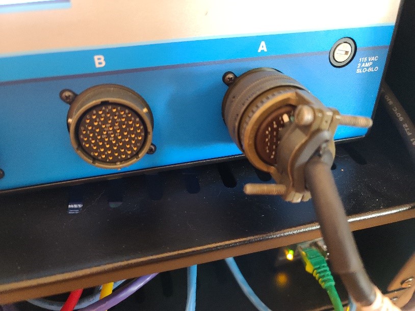
Figure 14. Photo. TS 2 connector for signal heads.
Source: FHWA.
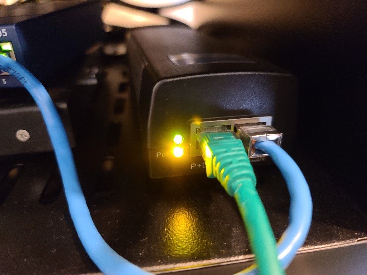
Figure 15. Photo. PoE injector power for RSU.
Source: FHWA.
- Ethernet Connection. The data connection among components is made using Gigabit Ethernet. The higher-end data throughput available with the Ethernet is sufficient to enable current and future updates to the system. The Ethernet connector RJ-45 connects the V2X Hub computer, RSU, and TSC to the unmanaged network switch, which is also connected to a Wi-Fi router that acts as the gateway.
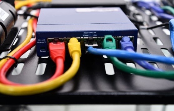
Figure 16. Photo. Ethernet switch.
Source: FHWA.
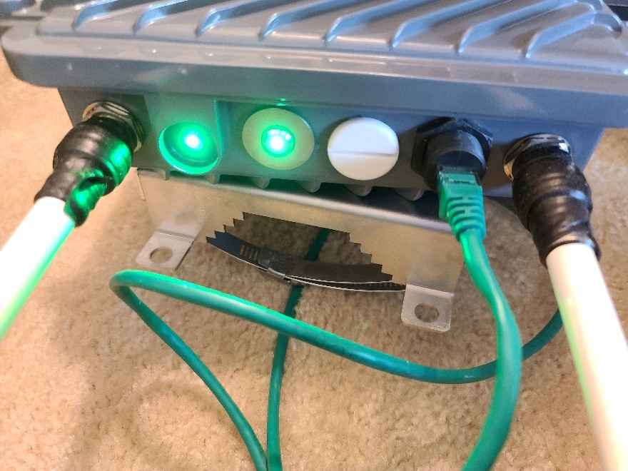
Figure 17. Photo. Power and data connector for the RSU.
Source: FHWA.
- Display and Input Interfaces. The touchscreen available as part of the kit connects with the V2X Hub computer using an HDMI port for display. It uses a USB port for the keyboard and mouse connections. Bluetooth options are also available.
- Wireless Router. A wireless switch is connected with the wired switch that allows external devices to connect with the kit. The wireless link is expected to have a password and encryption enabled for securing access to the test kit. The router has Dynamic Host Configuration Protocol (DHCP) enabled for Wi-Fi clients to reduce connection and configuration time. The wireless and wired interfaces are on the same subnet to enable efficient communication.
INTEGRATED SYSTEM DIAGRAMS
With the components and connections described previously, the various versions of the infrastructure and mobile kits for CAVe-in-a-box can be built, as shown in Figure 18 through Figure 21. The interconnection diagram in Figure 18 shows the connection and bridging of different components to build the infrastructure kit. If a wireless connection to the components of the kits is needed, then a wireless router can be configured to allow a Wi-Fi network with users outside the kit. The wireless router is also available with cellular network support, which allows remote connection with CAVe-in-a-box. The wireless router will also have DHCP that assigns IP addresses to each of the connected components. The address assignment can be fixed based on the type of device (hardware address-based). The wireless router can also provide Network Address Translation for isolating the subnetwork inside the CAVe-in-a-box and allow a single interface for secure internet access. The connections needed for the infrastructure kit are shown in Figure 18, such as power connection between each of the devices, including the PoE required for RSU, wired connections required among RSUs, TSC and V2X Hub computer through a single wired network switch. The connectors required for different components are also shown in Figure 18. This setup is vendor-specific; certain connectors and interfaces may be different for different vendors, so it is highly recommended to reference the vendor-specific manuals. An additional diagram of CAVe-in-a-Box with C-V2X radio and Connected and Automated Vehicle Education Research Software (CAVERS) integration can be found in Appendix B.
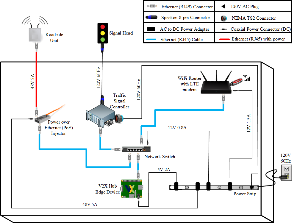
Figure 18. Diagram. Infrastructure kit integrated connection diagram.
For the full description click here.
Source: FHWA.
The interconnection diagrams for the mobile kit are shown in Figure 15, Figure 16, and Figure 17. The mobile kit is envisioned to have three potential versions that may have varying amounts of equipment. The OBU with a wireless radio is common among all three versions and has the primary task of communicating with the connected environment. Figure 19 shows the version without any wireless networking support, called mobile kit type 1. This version of the mobile kit allows users to interface with the kit using a USB to Ethernet connection with a tablet PC or laptop. The OBU is powered using an inverter through the car DC power supply. This type of mobile kit does not have internet or remote access support. The antennae shown in Figure 19 are mounted on top of the vehicle where this kit is installed. Therefore, the wires need to be routed inconspicuously along the frames of the vehicle.
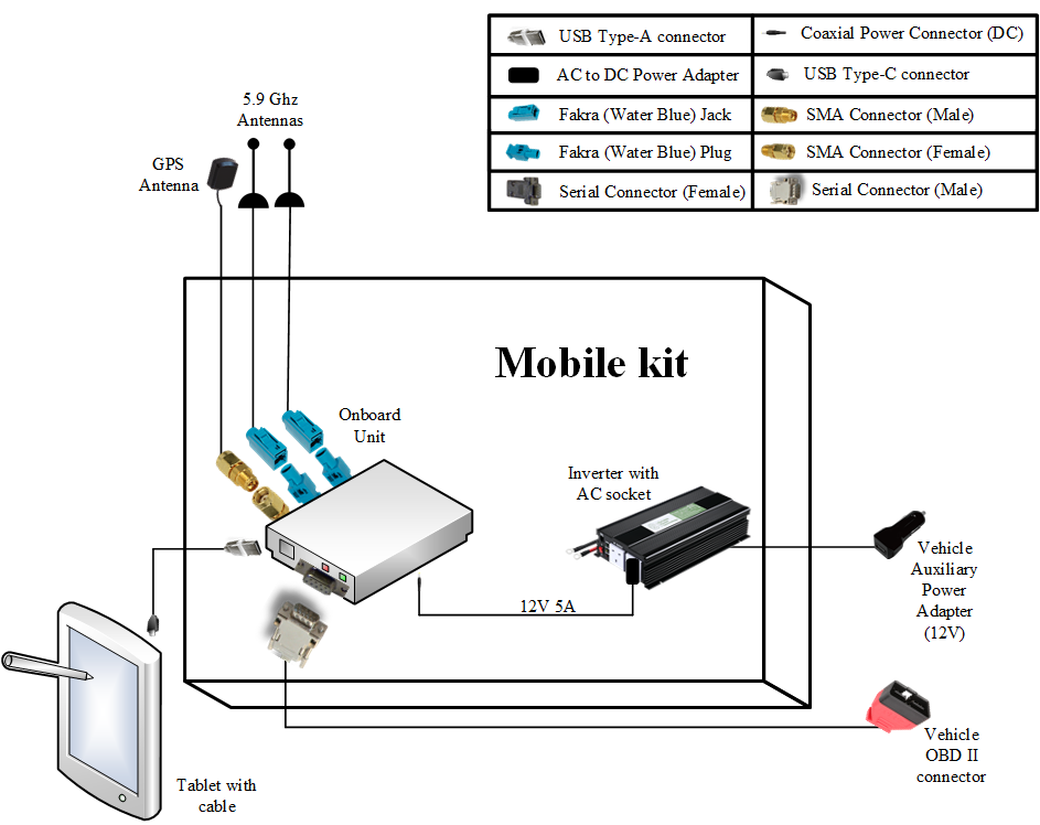
Figure 19. Diagram. Mobile kit type 1 integrated connection diagram.
Source: FHWA.
The second type of mobile kit (type 2) is shown in figure 20. This version of the mobile kit has an internal wireless router that allows wireless connection with users but lacks cellular service. Therefore, this version also lacks remote access support for the mobile kit.

Figure 20. Diagram. Mobile kit type 2 integrated connection diagram.
Source: FHWA.
The third type of the mobile kit (type 3) is shown in Figure 21. This version of the mobile kit has a wireless router with cellular service (like the infrastructure kit), allowing remote access to the mobile kit, if needed.
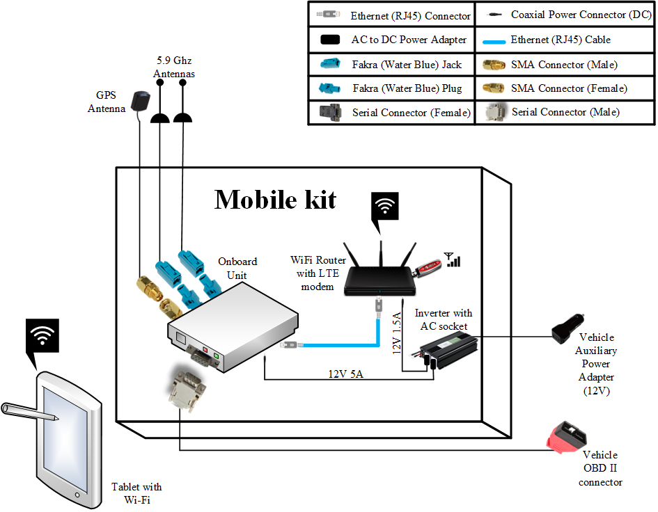
Figure 21. Diagram. Mobile kit type 3 integrated connection diagram.
Source: FHWA.
VENDOR LIST
There are many vendors available for supporting the construction of a test kit like CAVe-in-a-box. The kit has been designed with generic interfaces and requirements so that many vendors are able to provide support. Table 1 provides a list of some of the commonly available components with their respective vendors.
Table 1. Vendor list for CAVe-in-a-box.
| Component |
Used in this Document |
Vendor |
| TSC |
Econolite |
Econolite Cobalt Rackmount, McCain 2070 EN1, ASC/3 Rack mount Econolite, Commander Trafficware, Peel, Intellight |
| RSU |
Cohda |
Cohda, Lear, Savari, Kapsch, Siemens |
| OBU |
Cohda, Savari |
Cohda, Lear, Savari, Kapsch |
| V2X Hub computer |
nanoPi |
Raspberry Pi, NanoPi, Intel NUC, Asus Tinkerboard |
| Touchscreen |
Asus, Windows tablet |
Windows/Android tablet |
Previous | Next