← Table of Contents
CHAPTER 3. SETUP AND CONSTRUCTION
CAVe-in-a-box is a toolkit that is used out in the field and in academic settings to test devices and act as an aid to educate future transportation engineers. The toolkit consists of a box housing multiple devices that allow for V2X communication. This section provides information on building the CAVe-in-a-box, with a focus on the infrastructure kit due to the need for rugged outdoor use cases.
SOLIDWORKS REPRESENTATIONS: INFRASTRUCTURE KIT
This section will provide a visual representation of the infrastructure kit with all of its components inside using the SolidWorks software (D. Systèmes, 2020). Figure 22 displays the TSC shelf. Due the size of the TSC, it has its own dedicated shelf in the infrastructure kit. The TSC is mechanically fastened to the shelf with the use of screws.
Figure 22. Illustrations. TSC shelf.

Figure 22A. Front view of TSC shelf.
Source: FHWA.
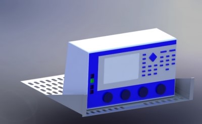
Figure 22B. Orthogonal side view of TSC shelf.
Source: FHWA.
Figure 23 displays the component shelf. The devices included on this shelf are the network switch, PoE, boundary V2X, V2X Hub, and the network Wi-Fi router. To represent the Ethernet connections, the Ethernet ports on the devices have been color-coded. Because the initial CAVe-in-a-box is a prototype, these devices are affixed to the shelf via hook-and-loop fasteners. This allows for rapid replacement of devices. Further iterations will require brackets to be made for some of the devices to properly fasten them down.
Figure 23. Illustrations. Components in the shelf design (isometric views).
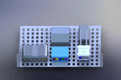
Figure 23A. Top view of component shelf.
Source: FHWA.
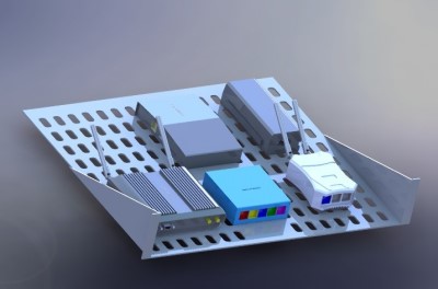
Figure 23B. Side view of component shelf.
Source: FHWA.
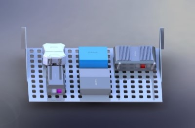
Figure 23C. Rear view of component shelf.
Source: FHWA.
Figure 24 displays front views of the infrastructure kit as an assembled box. For this iteration, the TSC shelf is mounted above the component shelf. From this angle, two of the color-coded Ethernet connections are visible.
Figure 24. Illustrations. Completed SolidWorks design of a CAVe-in-a-box infrastructure kit.

Figure 24A. Illustration. Front view of the CAVe-in-a-box design.
Source: FHWA.
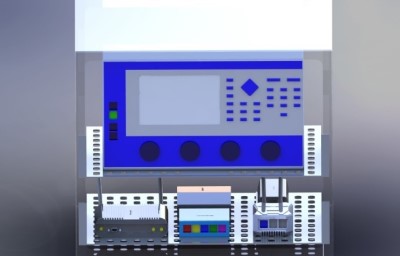
Figure 24B. Illustration. Tilted front view of the CAVe-in-a-box design.
Source: FHWA.
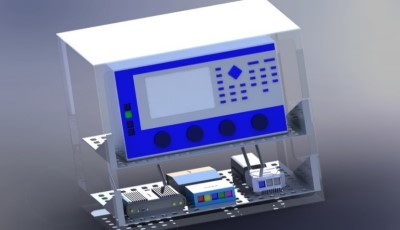
Figure 24C. Illustration. Side view of the CAVe-in-a-box design.
Source: FHWA.
Figure 25 displays rear views of the roadside kit. Here, the remaining color-coded Ethernet connections are visible. In the actual device, cabling is routed neatly between the devices to provide DC power and Ethernet connectivity.
Figure 25. Illustrations. Rear view of the completed CAVe-in-a-box infrastructure kit.
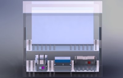
Figure 25A. Illustration. Rear view of the CAVe-in-a-box.
Source: FHWA.
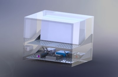
Figure 25B. Illustration. Rear side view of the CAVe-in-a-box.
Source: FHWA.
Current Kit
The current infrastructure kit design is a proof-of-concept that serves as a base for further product development while enabling a real-time view of working components. For this kit, the goal was to develop a case that could highlight the devices and technology being used. With this goal in mind, a simple rack mount case with two shelves was used. Except for the TSC, the kit components are held in place with a hook-and-loop fastener for two reasons: the components do not have built-in mounting locations, and this setup preserves the modularity of the design.
Future Design Alterations
Because the proof-of-concept version of the infrastructure kit has been established, the next step is to consider future design alterations that improve the function of the kit. First, for this kit to be used in in the field, a weather-proof case is needed to protect all the components inside. Sliding shelves in lieu of rigid mount shelves would allow for the exchange and access of components. Second, installation of red, yellow, and green signal light LEDs would make it easier to quickly determine the phase that the TSC is in without requiring the kit to be directly plugged into a signal head. Further design modifications that would allow this kit to be more robust include adding cooling fans, shock mounting the components, or mechanically fastening all devices to the shelves. This would be done by fabricating bracketry that can then be either drilled and tapped or through-bolted to securely mount devices. Lastly, a more secure RSU mounting location on the kit will need to be determined without inhibiting the durability of the case.
CAVe-in-a-box is durable and weather-proof. For this iteration, the Pelican Mac-Rack MR1917 has been chosen. It utilizes a 9U rack that can be dismounted from the box for installation and removal of equipment. This box also utilizes all stainless-steel hardware and sliding shelves. Both lids are mated to the box with weather tight seals to prevent any water intrusion into the box.
The box has been modified for this project’s specific purposes to include weather tight grommets to allow for wires to pass through the box while the lids are attached. An outdoor electronics’ cooling fan has also been added to monitor interior temperature. Red, green, and yellow lights have been flush mounted to the box to serve as indicators of the traffic signal phase. A specialized bracket has been constructed to mount to the box as well to allow for the installation of an RSU.
Within the box, the top shelf is outfitted with a Cobalt (model) TSC. This controller has been mechanically fastened to the shelf via machine screws to ensure that the controller stays in place and cannot come loose. Power is fed to the controller via a 120V power supply mounted on the interior backside of the box.
The second shelf within the box contains the other necessary hardware that enables the toolkit to serve its desired function. These devices include the V2X Hub, network switch, network router, a PoE, and the necessary Ethernet cables to connect the devices.
Once constructed, the shelves are mounted to the rack within the box with machine screws. The rack is then re-installed into the box and attached to the shock mounts within the box.
SOLIDWORKS REPRESENTATION: MOBILE KIT
The purpose behind the design of the CAVe-in-a-box mobile kit is to create a device that can be placed into a vehicle, connect to the vehicle’s OBD2 port, and serve its function as a mobile onboard communications device.
Items included in the mobile kit are the OBU, a wireless network router, and a tablet screen PC to display information. The tablet PC is mounted on the lid to give the user the ability to view the screen within the mobile kit. This keeps the design of the kit integrated. The wireless network router and the OBU are mounted within the kit in a way that allows for access to the antenna connections and CAN connectors. As shown in Figure 26 and Figure 27, a 120V power strip is included to provide power to the devices via an existing inverter installed inside of the anticipated test vehicle. Future design alterations will allow for a 12V inverter or power supply to be mounted within the mobile kit.
The compact, mobile, and integrated design of the CAVe-in-a-box mobile kit allows for testing, as a single kit may be used for multiple vehicles.
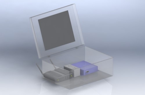
Figure 26. Illustration. Completed SolidWorks design of a CAVe-in-a-box mobile kit.
Source: FHWA.
Figure 27. Illustrations. CAVe-in-a-box side profile.
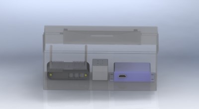
Figure 27A. Illustration. Front view of CAVe-in-a-box mobile kit side profile.
Source: FHWA.
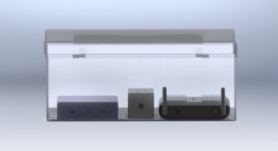
Figure 27B. Illustration. Rear view of CAVe-in-a-box mobile kit side profile.
Source: FHWA.
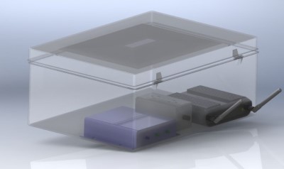
Figure 27C. Illustration. Isometric view of CAVe-in-a-box mobile kit side profile.
Source: FHWA.
Previous | Next