← Table of Contents
CHAPTER 5. DATA FLOWS
This chapter discusses the different types of data, including their source and destination, and how they are managed by different applications within the scope of CAV. This chapter tries to bring an extended ITS scenario into the scope of CAVe-in-a-box so that readers can understand how CAVe-in-a-box acknowledges the real CAV environment. The communication networks available in the CAVe-in-a-box toolkit include a wireless vehicular network using DSRC or C-V2X and a wired network. The messages between the RSU and the OBU are exchanged via a wireless DSRC network, and the messages between the V2X Hub computer, TSC, and RSU are exchanged on a wired Ethernet network. Every application supported by the CAVe-in-a-box has its own set of messages that are exchanged between the interlinked components. The messages sent by V2X Hub for broadcast follow the SAE J2735 standard and are used to convey ITS-relevant information between infrastructure and mobile components. In the case of this setup, the messages are exchanged primarily between the mobile kit and the infrastructure kit. V2X Hub is the managing component in the kit that handles every message that is received by the kit as well as messages that are to be broadcasted from the kit. V2X Hub generally acts as a middleware, handling messages and data from different protocols and standards and cross-translating them for efficient functionality of the overall system.
Figure 28 shows the component data flow diagram for the BSM application responsible for broadcasting vehicle status and positioning information to surrounding vehicles and nearby infrastructure. An OBU gathers information about vehicle status, such as the brake status and the steering wheel position, from the CAN bus connector and appends it with GPS localization information such as latitude, longitude, and altitude to create a unique BSM. The BSM is then broadcasted using WAVE over the wireless interface. WAVE is a hierarchical upper-layer protocol that manages messaging and networking by using the broadcast capability of the wireless interface. The BSM is forwarded to V2X Hub by the RSU after receiving it through the wireless interface. The BSMLogger plugin in V2X Hub is capable of decoding and logging the BSM received from different vehicles.
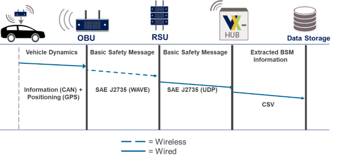
Figure 28. Diagram. BSM data flow diagram.
For the full description click here.
Source: FHWA.
Figure 29 shows the data flow diagram for the SPaT application. The SPaT application runs with the plugin of the same name in V2X Hub. The TSC initially sends the SPaT message to the V2X Hub in NTCIP 1202 V3 format, updating the signal, phase, and timing information for the intersection. The SPaT plugin in V2X Hub creates an SAE J2735 standard SPaT message using the information sent by the TSC, which is then forwarded to the RSU for broadcast. A vehicle within the range of the RSU receives the SPaT message through the wireless interface. In this case, the message flows from the infrastructure kit to the mobile kit.
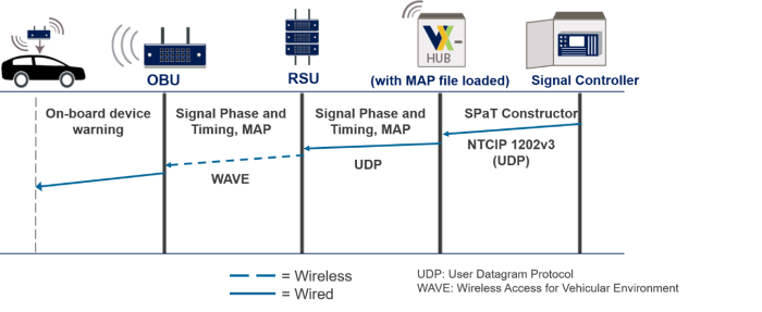
Figure 29. Diagram. SPaT message data flow diagram.
For the full description click here.
Source: FHWA.
The TIM allows vehicles and drivers to receive updates about lane closures related to work zones and incidents on the roadway. A TIM originates at a higher layer managerial entity, like the traffic management center (TMC), and is pushed down to the vehicles through the RSU. V2X Hub maintains a web server end point that allows the TMC to send the TIM message constructor information, which is then used by V2X Hub’s TIM plugin to create a TIM that is forwarded to the RSU for broadcast. In addition to the TIM, the higher layer entity will also send out a timing schedule specifying when to start and stop the TIM broadcast for each RSU. Figure 30 shows the data flow for the TIM application.
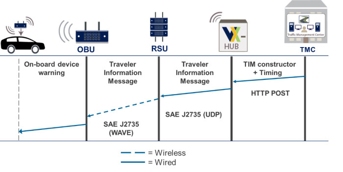
Figure 30. Diagram. TIM data flow diagram.
For the full description click here.
Source: FHWA.
PSMs are used by the infrastructure to warn nearby vehicles of the intention of a pedestrian or cyclist to cross the roadway. PSMs are very important for intersections and mid-block crossings that are not equipped with feed-forward inputs for pedestrians and cyclists to indicate their intentions to cross the roadway. A nomadic device, such as a cell phone, equipped with applications to send the PSM constructor call to the V2X Hub, through Wi-Fi or cellular networks, by utilizing the webserver is needed for this application to function. The PSM constructor call to V2X Hub is used to create a PSM, which is then broadcasted using the RSU to all nearby vehicles for warning purposes. Figure 31 shows the data flow diagram for the PSM application.
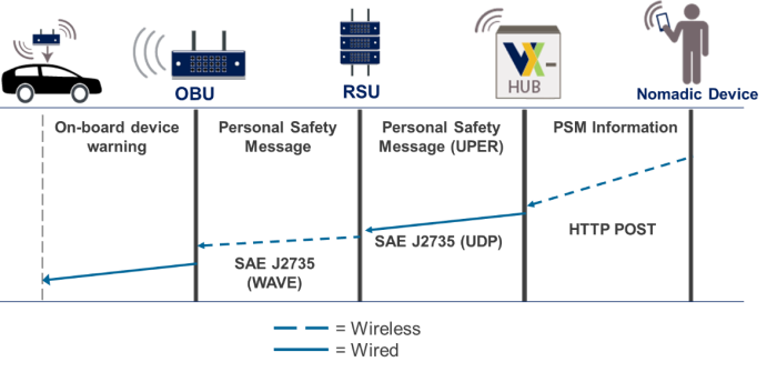
Figure 31. Diagram. PSM data flow diagram.
For the full description click here.
Source: FHWA.
Previous | Next